My next build--A cross beam vacuum engine

Home Model Engine Machinist Forum

Help Support Home Model Engine Machinist Forum:

This site may earn a commission from merchant affiliate links, including eBay, Amazon, and others.

Brian Rupnow

Design Engineer
Project of the Month Winner
Joined
May 23, 2008
Messages
14,978
Reaction score
8,270
Location
Barrie, Ontario, Canada
I just ran across this video today. I like this, hadn't seen one like this before. There is enough info in the video for me to design one from scratch. I've had a bad case of "engine building burnout" this summer, and am still working on my V-twin engine, but when fall comes I think I will design and build one of these.
 
I have a small "flame licker" engine that I built a few years ago from somebody elses plans. It doesn't have any power, but it is fun to watch running. A bit more research shows me that this engine is built and marketed from China. So----This will be a copy of a Chinese engine.--Kinda turnabout, isn't it.
 
And that in turn was quite possibly based on Jan Ridder's twin flame licker with the burner being taken from a Bengs design.
 
Today I'm bored---and that's always dangerous!! I found a side view of the Chinese flame sucker that I admired, printed it out, and established a scale factor based on the fact that the cylinder outer diameter is 38 mm. This let me go ahead and using that scale factor determine the rest of the dimensions. Once I had the dimensions, (or at least close to them) I was able to go ahead and make a model. This is essentially, a copy of a copy of a copy. It looks kind of neat.---Gave me something to do this morning.
0xGBW1.jpg
 
Thanks for posting the video Brian. It clearly shows how sensitive this is to the size and position of the flame. Explains why my Chinese model fails to run.
But my model has no clue to the port timing. After the first few spins when I first tried it, the valve timing slipped, and by trial and error I haven't got it working yet. Does anyone have the valve timing - shutter opening and closing timing?
K2
 
Will depend a bit on the cam profile and whether you have an exhaust valve or not but mine that I made open the flame port about 5deg before TDC and close about 25deg before BDC


I wonder how the hook to the valve plate will work? Is the valve plate just a flat plat with square end? Or is it a longer plate with a hole that opens when it aligns with the hole in the cylinder head?
K2
 
The flat plate is just rectangular with a hole in one end for the hook. It slides up and down in a slot in the cylinder head. Plate is up, uncovering hole. Piston goes from top dead center to bottom dead center, drawing flame into cylinder. Plate moves down and closes hole in end, flame inside cylinder goes out and creates a vacuum, which pulls piston back to top dead center, then entire sequence repeats.
 
The valve plate is not a tight fit in the slot it rides in--it more or less floats in there. The vacuum created by the piston moving towards bottom dead center sucks the plate against the cylinder head tight enough to keep the flame from entering the cylinder. The flame suckers are strange engines---They do not depend on pressure acting against the top of the piston. They depend instead on vacuum created when the flame goes out to "suck" the piston from bottom dead center back up to top dead center, and the flywheels carry the piston "over the "hump" and then the valve is opened again and the sequence repeats.
 
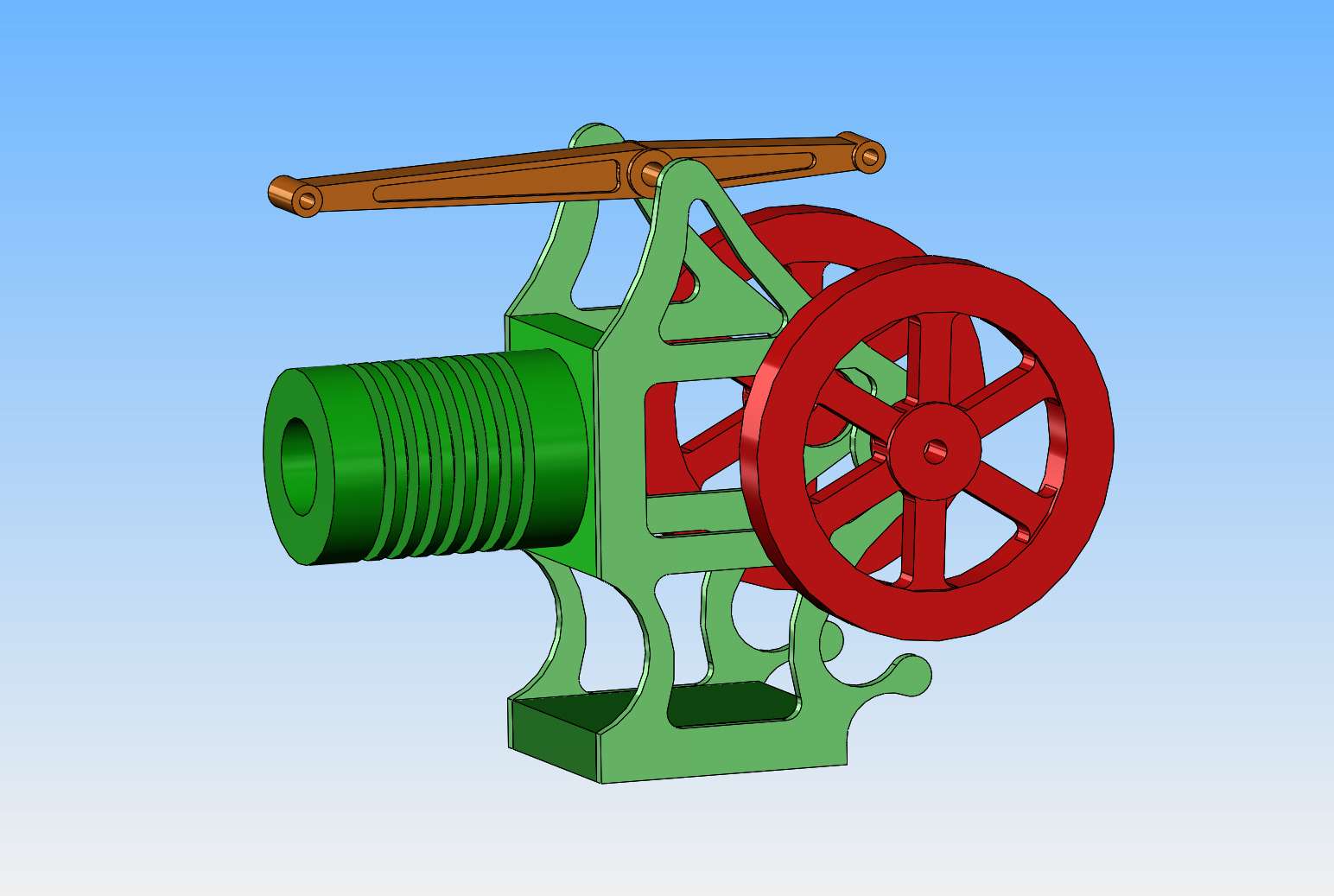
Hi Brian, from the CAD picture I thought it looked like the hook would become un-hooked on the valve-closure stroke at speed...?
I understand the "vacuum" engine principle, or "atmospheric engine" as it was called when Newcomen developed his first "Steam" engine.
I have wondered about the flame inside the cylinder? Does the flame - especially when comprising yellow parts = burning gas heated particles. - heat the gas slightly and increase the pressure in the cylinder before it cools and the pressure drops? - Would earlier valve closing timing be better on the intake stroke, so there is a moment for any increasing pressure from the remaining combustion to drive the piston to BDC, before the "vacuum" is developed and sucks the piston to TDC? - Seems I should make an engine with variable valve timing to "suck-it-and-see"?
Did you know that Hero (the Egyptian fellow a few Millenia ago) used the "Vacuum" developed in a condensing steam chamber to pump water to open and close the Temple doors, at a commend from the Pharaoh, so the Pharaoh appeared to operate the doors by "god's will"? - Credited with the first Steam engine, and first Atmospheric engine, but also hydraulics? The steam pressure was used to fill a chamber, at some height and connected to the boiler and a reservoir. When the condensing steam developed the vacuum to draw-in water from the reservoir, it was used as a weight to open the doors via a pulley, rope and lever system. The released weight of water then permitted the doors to close as falling a counterweight then returned the system to rest. - I think?
The Hero turbine was the first rotary steam engine (turbine) also, using reaction jets. It took a couple of thousand years before Newton developed the reason that reaction jets work, by maintaining the total momentum of the system. (M1v1 + m2V2 = 0, M1v1 being the "Hero turbine" and m2V2 being the steam expelled.).
Did you know that the early industrial "flame eaters" were also very large early "fire-engines" by consuming the flames and hot smoke from coke furnaces (which made coke for smelting in steel works) and drove large turbine centrifugal fan) air blowers that were used to blow air through the molten iron to de-carbonise it to make steel? By using these engines, they eliminated the steam boilers and steam engines previously used. But they suffered very high wear rates from the smoke and ash and corrosive acids in the exhaust they were breathing.
History. a good place to begin....

K2
 
That is probably why the kit one gas a flat bottom to the hook, so it will close the port off by pushing the shutter back into it's slot.

N.L. Otto patented a "flame sucker" in 1873 for an engine that drew in gas that was ignited as it was drawn in by a pilot flame so there was a small amount of expansion from the burning gas towards the end of the intake stroke once the inlet shutter had closed, it then used the vacuum of the cooling gas to complete the cycle and bring the piston back up to TDC. I've not quite finished my one of these as I got distracted by other engines.

A nifty arrangement of a pivoted scotch yoke meant that the piston moved faster on the intake stroke than the return
 
I knew about Hero's steam turbine, but it was only treated as a toy and never developed farther. As for the other stuff Hero may have done, I am not aware of it. Is there an increase of pressure just before the candle flame in the cylinder goes out----I doubt it.
 
Thanks Jason, Brian.
"That is probably why the kit one has a flat bottom to the hook, so it will close the port off by pushing the shutter back into it's slot." - That explains a lot... I had figured maybe there was a vee-notch or radius on the inside of the hook to do that. - I had guessed it needed a gudgeon pin adding to the top of the blade, with a close fitting eye in the small link to replace the hook, for a "proper job".
I had not considered varying piston speed as you mention, Jason.
"A nifty arrangement of a pivoted scotch yoke meant that the piston moved faster on the intake stroke than the return". - I guess this meant the extended cooling was more complete, so more power produced?
I have a boat with boiler pump (single cylinder) arranged so the inlet stroke (atmospheric) is just about 3 times quicker than the pumping stroke (Boiler pressure up to 3 bar) so the engine load hardly varies between inlet and pumping strokes.... which makes the boat run smoother!
I'll be interested if you have anything more on the modified scotch yoke mechanism you mention, because I have something that may be a similar idea too...?
I use a crank driving a slot in a lever... when the lever driven point is close to the fulcrum, the mechanical advantage is lower (for sucking water into the pump: at atmospheric pressure), when the crank is away from the fulcrum, the mechanical advantage is higher (for pumping against 3 bar boiler pressure, so it can open the delivery non-return valve)... But the lever "take-off" position adds complexity to the motion... Needs a drawing to show. (Another job to do!). It could be possible with additional levers to replace the eccentric drive for the valve plate on this flame licker? - If there was any advantage to have different opening and closing speeds for the valve?
Some infernal combustion engines have the crank centre off-line to the cylinder axis - but usually to reduce piston side-thrust during the firing stroke.
Brian, Sorry to clog-up your interesting build with rubbish distractions (again).
K2
 
Last edited:
This is the scotch yoke arrangement, though I'm actually rotating the crankshaft in the wrong direction but you can see how one half of the rotation is faster than the other.


In fact if you laid this engine on it's side it starts to look a lot like Brian's with the two centrally pivoted levers effectively making a "beam" one end driven by the cam and the other sliding the shutter

otto beam.JPG


20220703_132839.jpg


This is a near full size replica, the horseshoe shaped part is where the gas is mixed with air and ignited by that external pilot burner before being drawn into the cylinder

 
The one thing to note is that the valve action is not a simple eccentric.
To work best, the valve needs to "snap" open and shut (relatively speeking).
And, the valve also need to seal. These engines don't like sloppy fits or binding in anyway.

Sid
 
Sid, sounds like a cam action is more appropriate han a circular eccentric?
Jason, your slotted lever is almost exactly like mine for the water feed pump on my boat! Great Minds...? n all that? - Or just some understanding of geometry...
K2
 

Latest posts

Back
Top