My next build--A cross beam vacuum engine

Home Model Engine Machinist Forum

Help Support Home Model Engine Machinist Forum:

This site may earn a commission from merchant affiliate links, including eBay, Amazon, and others.
If the flywheels were going on a gasoline powered engine, I would have made the spokes shorter so they were about 0.100" below the outside of the flywheel surface. Fill up that remaining 0.100" with weld from my mig welder, and then machined the o.d. until it was smooth. Pinning would work well also.
 
Today may be crankshaft day. I can't make my crankshaft "throws" the same as the ones used on the original machine, because I don't have the tooling required to make a 0.020" slot between the two shaft holes. That shouldn't be a problem, as I do have a one thou undersize reamer for the 1/4" diameter hole and an "on size" reamer for the 3/16" hole.
 
I am not familiar with this engine but with my experience with flame licker engines I do wonder if the engine has enough power to keep the relatively heavy flywheels turning. I am eagerly awaiting the conclusion of this design/build.
 
Today I parted off the flywheels, and the method I used actually works pretty good. I have to do a big clean-up on them next. This morning I also made the crankshaft and it's all Loctited together right now. Tomorrow I will cut the main shaft off between the two "throws". Now I'm off to cut my grass.
XdZJmb.jpg

U5iiP5.jpg
 
Today was make a con rod and clean up the flywheel day--and finish the crankshaft and pin the crankshaft 'throws' day. The flywheels came out very nice. Brafasco called and my box of #2-56 shcs are in, I will pick them up tomorrow--They hold the bearing housings onto the sideframes. Tomorrow I will make a piston. I have a 1" diameter stick of graphite setting on the end of my desk, that I bought 6 or7 years ago while building one of Jan Ridders engines, and I may use it to make a piston.
D0nAbi.jpg

i6G8fu.jpg
 
Today I added the set screws to my flywheels, drilled and tapped my sideplates for the #2-56 shcs that hold the bearing supports in place, added the ball bearings into the bearing supports and mounted the crankshaft, just to make sure everything was going to fit. Then I honed the cylinder inner bore and made a piston from the piece of graphite that I've had for years. Graphite is strange stuff to work with--it machines very nicely, but it is brittle.
jGoI3a.jpg

pms1U3.jpg
 
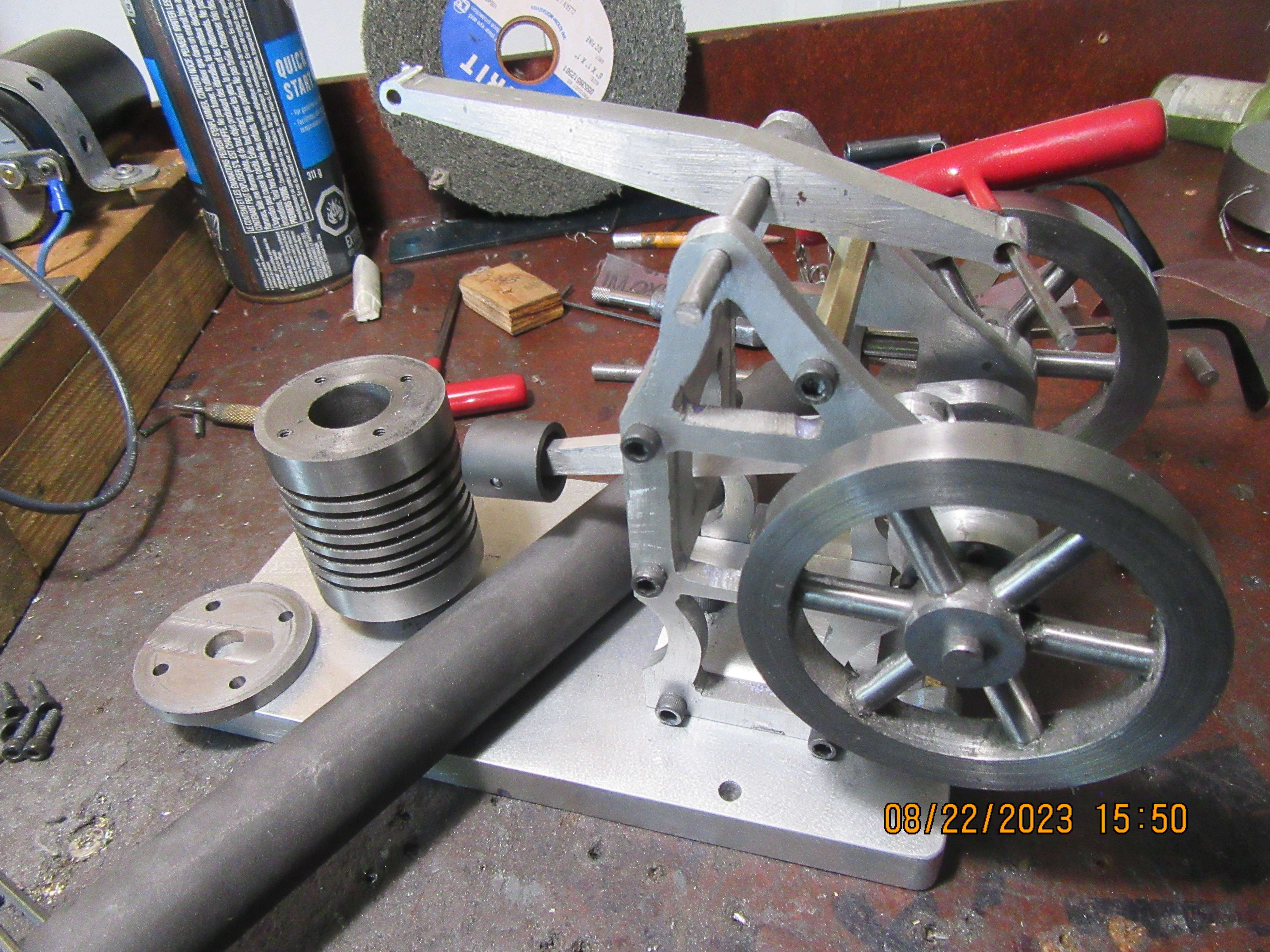
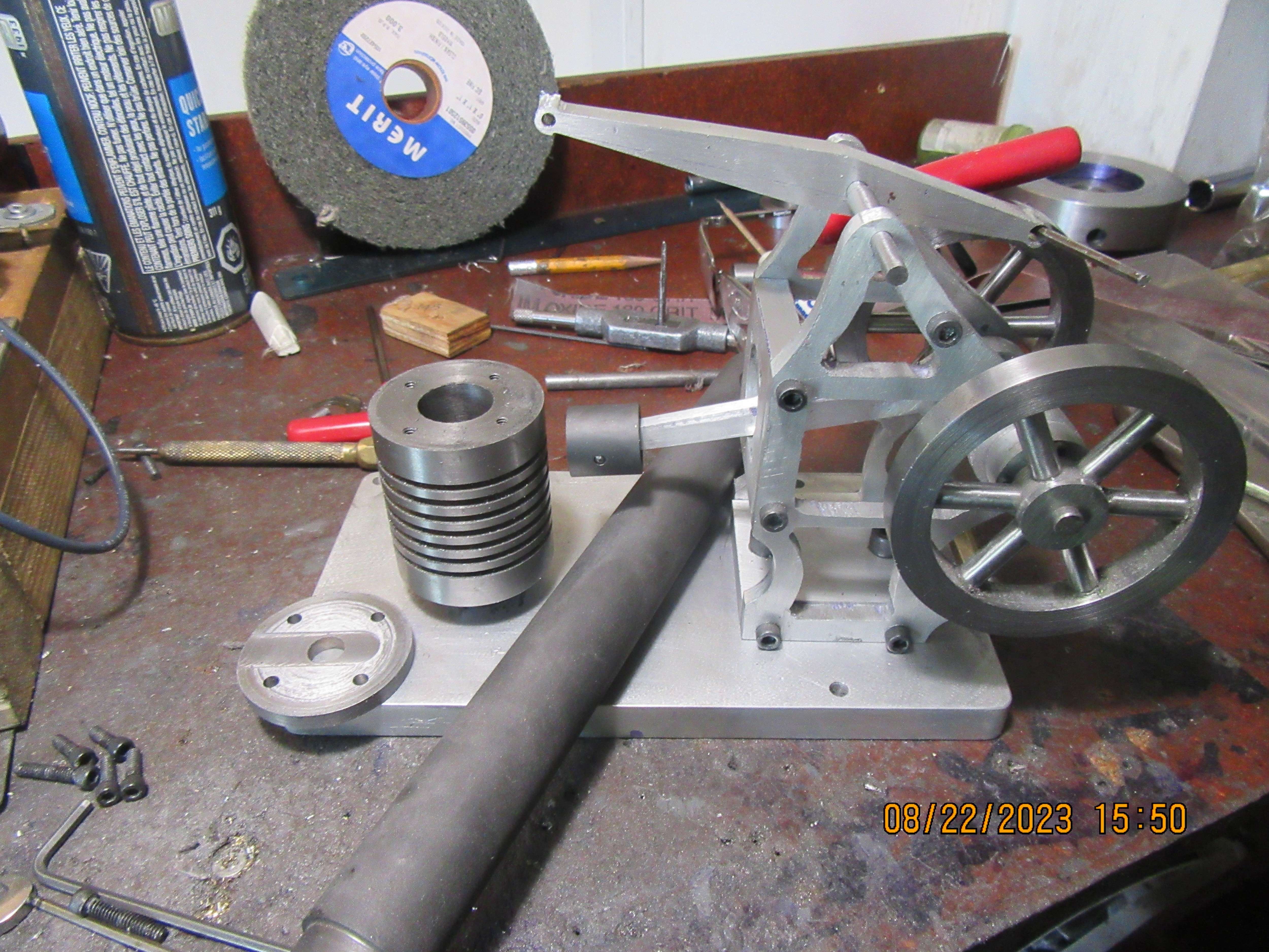
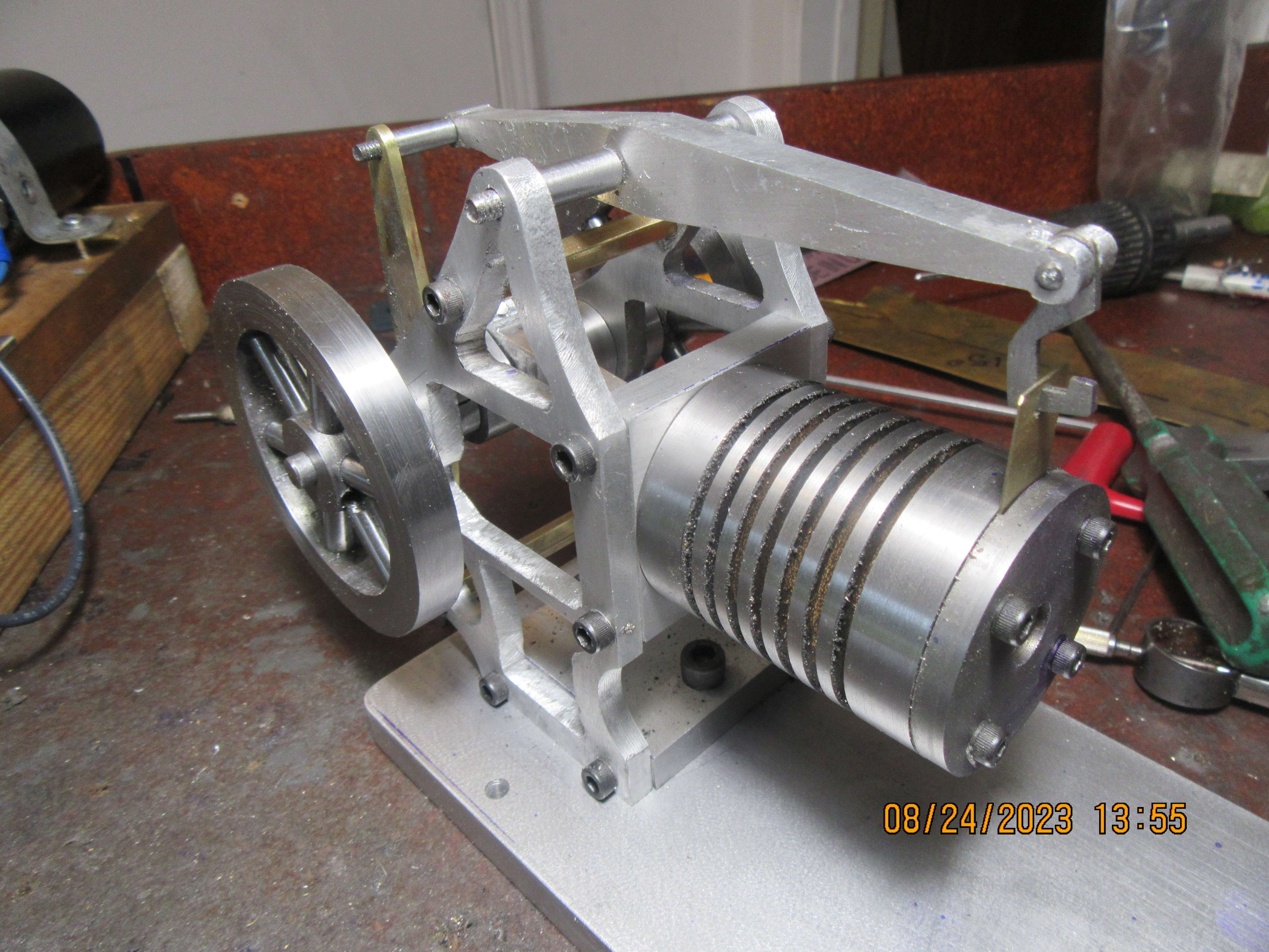
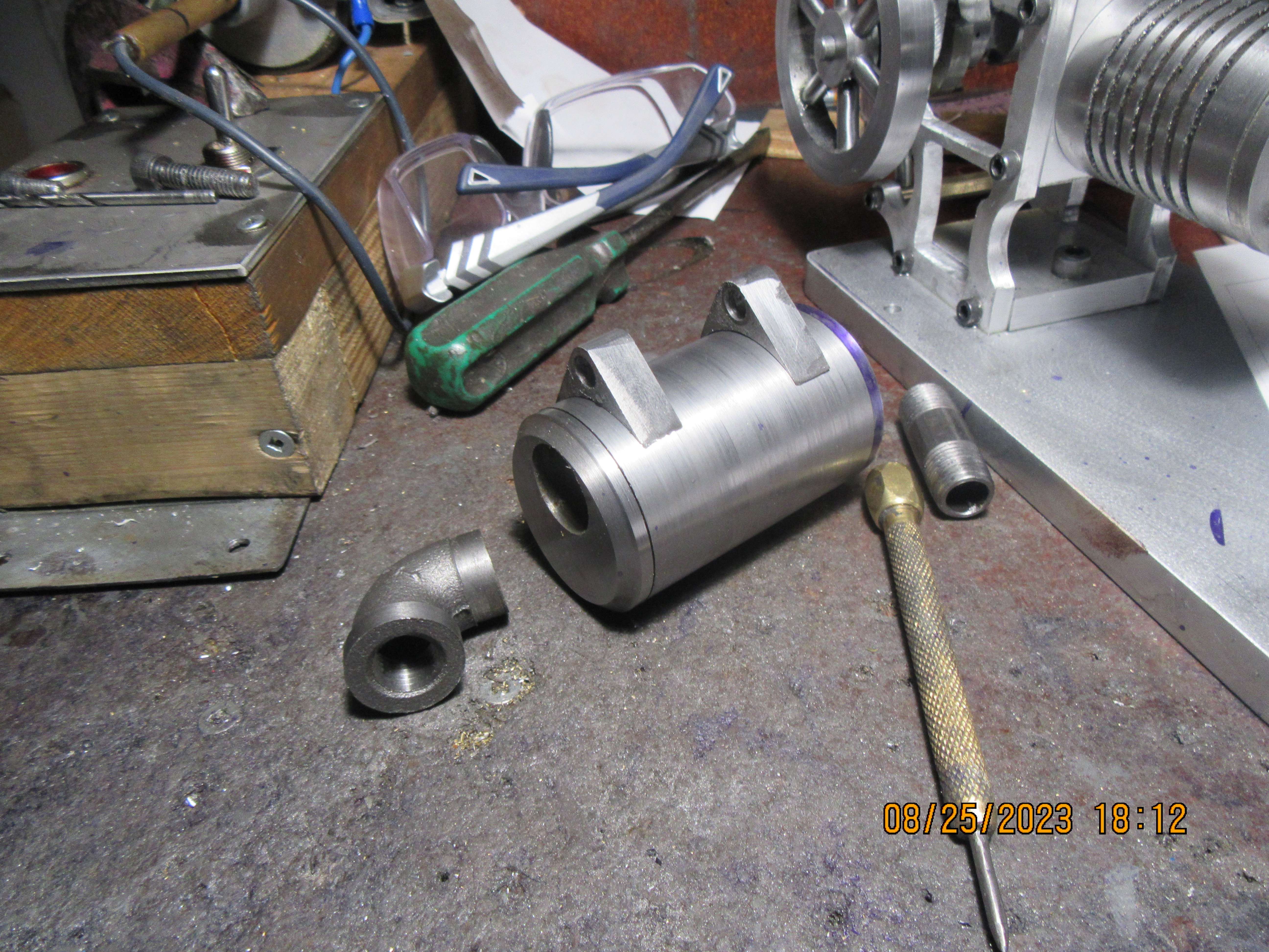
This build has literally raced forward. I am at the point where I only have three pieces left to make. One is a spacer to fit between the crank throw and the inside of one sideplate--that's an easy one. One is the lever that lifts the beam, and although a bit more complex, it should be relatively easy. The third piece is the cam, and I am rather "at sea" on that one. A few years ago I built the "Popping" flame sucker engine, and after studying the cam on it, I have an idea as to what I want to do.
 
The crankshaft spacer was easy. The cam---not so much. I had to extend the 0.020" wide sawcut much farther than I originally thought in order to have the #5-40 hidden inside the cam grip the shaft. I've used up most of a morning making those two parts. The lever which lifts the beam will actually be two parts welded together--I'll get to that this afternoon.
5yGTgJ.jpg
 
Okay!!!--I made the three pieces I set out to build this morning. Somehow it's suppertime. Where did my day go?--I'm glad I'm not paying myself to build these things. I might assemble everything after supper---or---tomorrow morning. Jason pointed out that I have the 0.020" sawcut on the wrong side of the cam, and he's right. I will change the detail drawing but will try and use what I made today.
j4l0Bm.jpg
 
While you are altering the drawing add a counterbore for the screw head and you may get an unexpected cam action as the follower bumps over the screw
 
Hi Brian, its looking good and i am anxious to see this one run. i remember when you built the imperialized version of Ridders flame eater and had trouble getting it to run as did i. incase you have issues with the graphite piston the fix for me on the flame eater was to let the flame heat the ss cylinder up to temp and then measure the i.d. then cut the piston to that size. to assemble you will have to heat the cylinder again up to run temp and when the engine cools the piston will be seized up but that was the trick to get mine running. apparently expansion rates of ss vs graphite are ALOT different and thus looses to much vacume when it gets up to run temp.
 
Looking thru my collection of "odds and sods" I have found a piece of 1.75" outside diameter x 1/4" wall black pipe. That should do nicely for a fuel tank for this engine. I have a design lurking in the back of my head, and will probably burn some computer time tomorrow doing up a design. I like the idea of having the fuel tank position adjustable to bring the flame closer or farther away from the front of the cylinder, because that is what determines the speed the engine runs at.
A81mGR.jpg
 
This morning I designed an alcohol tank for the engine. The adjustment won't give me a lot of movement, but it will allow a little bit, and these engines are very sensitive to a little bit of flame movement.
AkFqZr.jpg
 
Close but no cigar!!!-I got most of the fuel tank parts made today, but didn't get them assembled. I'll do that tomorrow morning, and then let the tank set for 24 hours, as the end caps are J.B. Welded in place.
AeuklB.jpg
 
I didn't think my alcohol tank position adjuster was going to work, so I redesigned it using one of my tried and true "Casey Jones" handles. There will be a couple of Belleville washers between the handle and the side of the base to keep the handle locked in whatever position I set it for. The alcohol tank is finished.
QaIR03.jpg
 
The engine is finished. I have to buy the correct size of pipe plug tomorrow to screw into that elbow on the alcohol tank as a "gas cap". The big question now is "Will it run"----I'll find out this week!!!---Brian

8BO9co.jpg

tTxQSM.jpg
 
Back
Top