My next build--A cross beam vacuum engine

Home Model Engine Machinist Forum

Help Support Home Model Engine Machinist Forum:

This site may earn a commission from merchant affiliate links, including eBay, Amazon, and others.
I spent some time this morning laying out a device to keep pressure on the flap valve so it would seal tightly against the end of the cylinder. Decided that yes, I could do it, but it sets directly above the hole in the cylinder head and would die a pretty quick death from the alcohol flame.--There is a compression spring in that assembly that I didn't show. Jason--I read all of your posts. I'm not sure what you are referring to in the previous post.---Brian
VpJzzT.jpg
 
It was a reply to Steamchicks previous post.

Problem with adding a pressure pad is it just creates more friction for the weak engine to overcome, spring will soon loose it's temper above the flame anyway.

Sounds like you have the valve shutter open a bit to long, try to have it open the flame port about 5deg before TDC and close about 25deg before BDC
 
Jason--I will take your advice and machine a new cam. The cam I am using is a direct copy of the Poppin engine cam, and I have the sawcut in the wrong side anyways. I will have to do some "crafty" calculations to show me what my new cam profile needs to be to be in order to give the timing you suggest. Thank you---Brian
 
Jason--A thank you to you. My Solidworks 3D software will do a cam follower mate for me, but it's something that I really don't use on a day to day basis. I had to watch a tutorial on it, found out the secret (again) and wrote it down in my book that I keep for seldom used Solidworks functions. Now I can design a cam that lets me accurately set my timing.---Brian
 
Hi Jason, yes, I did read your earlier post. And then thought a bit about "Why?" - would the valve closure be before BDC?
Sometimes, idly speculating on the "why" gives a better understanding of what is really happening, so the whole engineering can be tuned appropriately.
Then I usually find I am completely wrong and an expert laughs and explains the real answer!
So here goes with my idle ideas..
  1. During the initial part of the intake when the valve opens, the initial, colder, remnants of the previous stroke may still be slightly sub-atmospheric when the valve opens, so opening at TDC or thereabouts relieves the vacuum to "flame" so it does not work against the engine after TDC..
  2. As the engine progresses down the stroke it sucks in flame - and burning gases - so when the valve closes it may still have chemical energy converting to heat inside the engine. Closing the valve before BDC allows this internal combustion to increase the pressure and if above atmospheric will slightly power the engine.
  3. the late expansion of the combusting/combusted gases to BDC with closed valve should allow for the cylinder pressure to drop so it is not above atmospheric at the end of the stroke. - OR the pressure relief should manage it anyway, if fitted.
  4. Ideally, peak pressure should be before BDC, so the power of that pressure is not wasted, but the gases should be at or passing below atmospheric as the piston transitions BDC. Thus the sub-atmospheric pressure developing around BDC accelerates the piston back up the stroke to wards TDC, when the valve opens to relieve any residual vacuum.
  5. Hence the valve closure at 25 - 30 degrees Before BDC that you advocate.
It made sense to me, anyway.
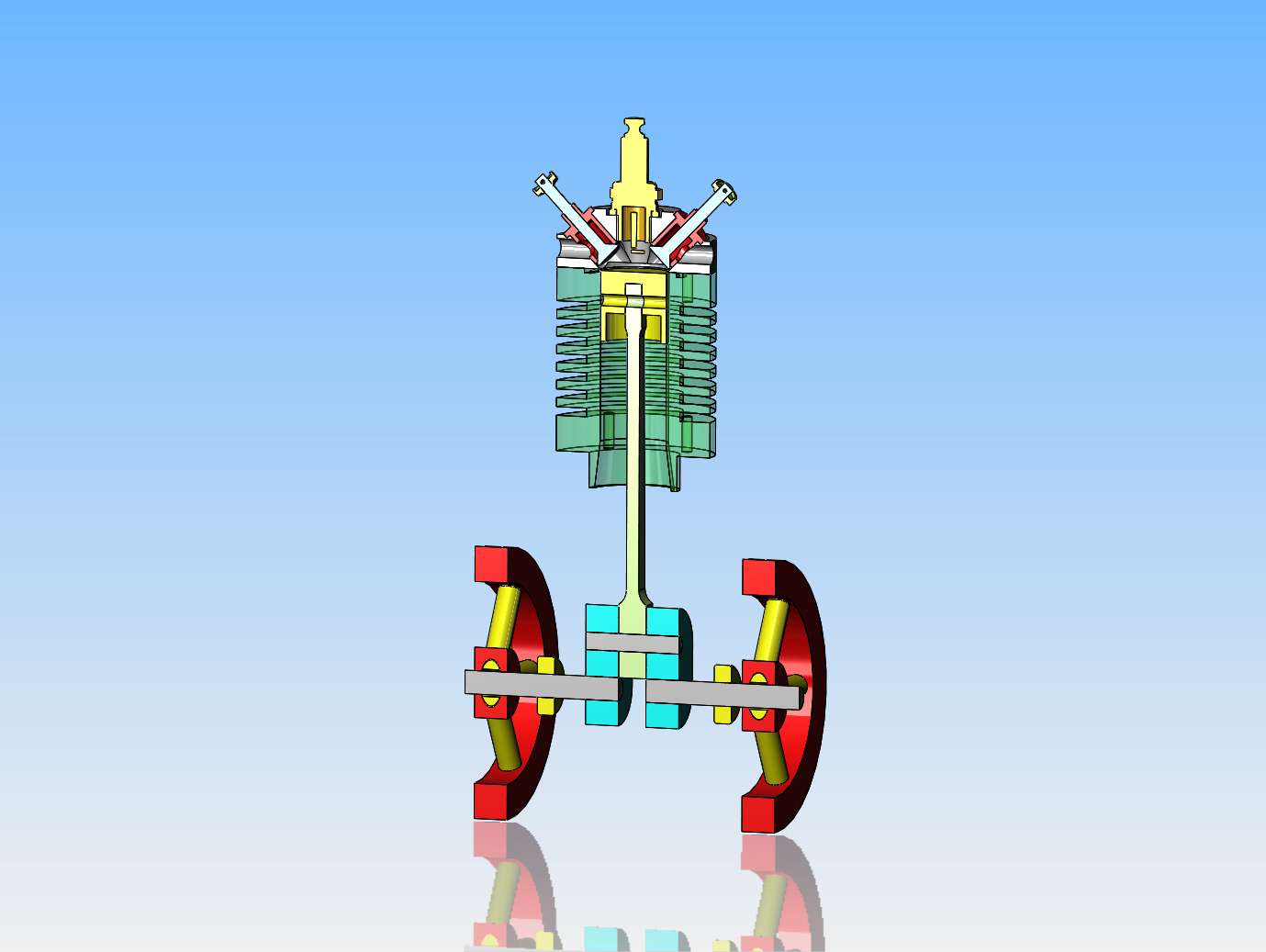
I suspect that the piston clearance of the worn graphite piston probably accounted for the lack of performance under vacuum that Brian experienced, as initially, he said it tried to work, but just didn't have enough kick (vacuum not maintained because the piston leaked too much?).
Watching various engines, some have blow-back as the valve opens. This suggests that somehow there is pressure above atmospheric at TDC, or when the valve opens? Perhaps better cylinder cooling is needed on those engines?

A very interesting thread. There is more to making these engines run than the "simple build" suggests!
Maybe I should make one with a glass cylinder to see what is happening inside the cylinder? - How much combustion takes place to raise the pressure above atmospheric?
K2
 
  1. During the initial part of the intake when the valve opens, the initial, colder, remnants of the previous stroke may still be slightly sub-atmospheric when the valve opens, so opening at TDC or thereabouts relieves the vacuum to "flame" so it does not work against the engine after TDC..
If sub atmospheric it will work with the engine after TDC as it expands to atmospheric and drives the piston down.

Watching various engines, some have blow-back as the valve opens. This suggests that somehow there is pressure above atmospheric at TDC, or when the valve opens? Perhaps better cylinder cooling is needed on those engines?

It's not the cooling, you suck in hot air and even after cooling it will have a volume and needs to go somewhere, either out an exhaust or out the intake which can blow the flame out if it's position is not right.
 
Brian, I would have expected the opposite, I've suggested timing that will close the valve for longer so as your beam needs to be pushed up to close the shutter I would have thought the high part of the cam should be greater.
 
Not having built a vacuum engine I can not comment but having built some hot air engines using cast iron pistons running in steel bores and piston rods running in cast iron bushes one thing I have learned is that friction is a killer and getting a good seal on the power piston and displacer rod is critical to function . I spray WD 40 up the bore of the Power piston and on the Piston Rod which is connected to a cross head assembly . that will last for about 30 minutes run time and provides the seal on both the piston and piston rod . bit messy . same applies to the ball bearings on the crank Assy . Has to be very thin oil otherwise to much drag . Cutting labyrinth grooves in the piston can also assist with contact surface area and a bit of the WD 40 assists .
 
I have been kicking around some notions as to what may be happening inside a Flame eater... in terms of pressure, expansion, cooling, heating, etc....
and have an idea we may have something like this?
1694509309493.png


I do not really know how to calculate what is going on, but have made some guesses ...
My hypothesis:
  • The inlet valve needs to open 5 degrees before TDC... or whatever - to permit the residual pressure or vacuum to clear before the piston sucks flame through a fully open valve.
  • Towards the end of the inlet stroke, the valve needs to close so it is completely closed a bit before the ed of stroke at BDC. This will allow the "vacuum" to start to develop so a good pressure difference (atmospheric to vacuum) appears almost immediately after BDC so the "power" stroke is maximised. Late closure (at BDC ??) could leave some hot-gas pressure when the piston starts the power stroke, delaying when it starts to do the real work.
As indicated on my picture/graph, the pressure below zero is "not working (Using power from the flywheel to energise the engine). Above the zero axis it is doing all the work of power from hot gas to flywheel. This doesn't consider friction and other losses.
I hope this matches your ideas? - or even experience?
K2
 
Okay boys--I've just made and installed a new cam that gives me the opening and closing time that Jason suggested. I will let you know later today what my results were.---Brian
 
This is a flame sucker engine that I recently finished. I haven't been able to get it to run, but yesterday I got some new information about timing from Jason in the U.K. I have machined and installed a new cam, but as always, when I tear an engine apart and then reassemble it there are tight spots in the rotation. In this video I'm just running the engine in for 15 minutes to loosen up any of the tight spots before I try it to see if the new cam shape and timing will give me a running
 
The might Casey has struck out----The new cam didn't make any difference to the way the engine ran---should I say didn't run. I've used up all of August and 12 days out of September on this engine, but it's a no go. It's not a total loss--I can re-use the alcohol tank, the crankshaft, con rod and piston, and the cylinder, maybe even the base. Not sure at this moment what type of engine I will use them on, but they will get used. Time for me to give machining a break for a while. I really expected to have a runner here, but it's not going to happen. I'll be back when I have decided what I'm going to do.---Brian
 
For what it is worth: I built a Duclos Flame Licker several years ago and could not get it to run for more than a few seconds so I put it away and did not think about it until you got working on this engine. I just took it off the shelf and tried firing it up. It started and ran for about 15 minutes. The valve is set to close completely at about 30° before bottom dead center and begins to open at about 40° before top dead center. That is about 170° with the valve closed. I think that is quite a bit different than what you have. I realize that they are different engine designs. Open means that it is open as soon as it start to uncover the hole and closed means that the hole is completely closed. Flame position is extremely fussy.
 
Gordon--Thank you for that. I went to bed last night thinking of how I can re-use most of the parts I have made on a four cycle petrol fueled engine. This morning I came downstairs to my office and designed what you see here. Everything is re-used except for the cylinder head and the funky side plates and the cross beam. A new cylinder head and conventional valves and valve guides can be made to work. Working with this software is just like a drug---I can get lost in it for hours. I will probably finish this new engine design and then start a new thread about it's development.---Brian
KcoAHk.jpg
 
I went to bed last night thinking of how I can re-use most of the parts I have made on a four cycle petrol fueled engine

Scary what that says about our age. Thirty years ago thinking about an engine design was probably not the first thing that we thought about. :)
 
Brian, can you post the dimensions of that revised cam and also say what OD the bearing follower is.

I don't know what software you used to create its timing but it looks like it is designed like an IC engine in that the lobe of the cam will open the valve. As you have a beam that will reverse things so your narrower looking revised cam will actually open he valve for longer not less time than I suggested
 

Latest posts

Back
Top