Moriya Build

Home Model Engine Machinist Forum

Help Support Home Model Engine Machinist Forum:

This site may earn a commission from merchant affiliate links, including eBay, Amazon, and others.

IronHorse

Project of the Month Winner!!!
Project of the Month Winner
Joined
Mar 3, 2008
Messages
243
Reaction score
20
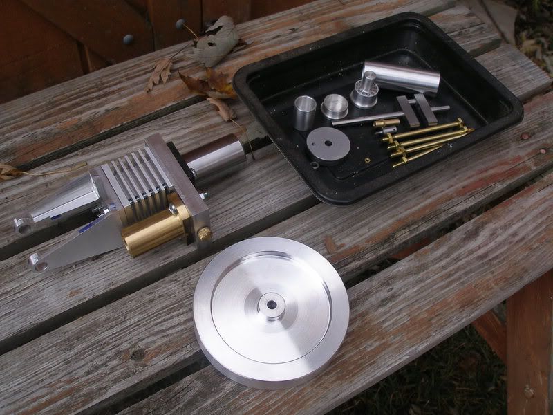
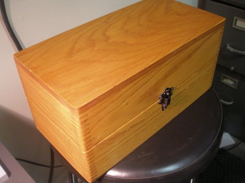
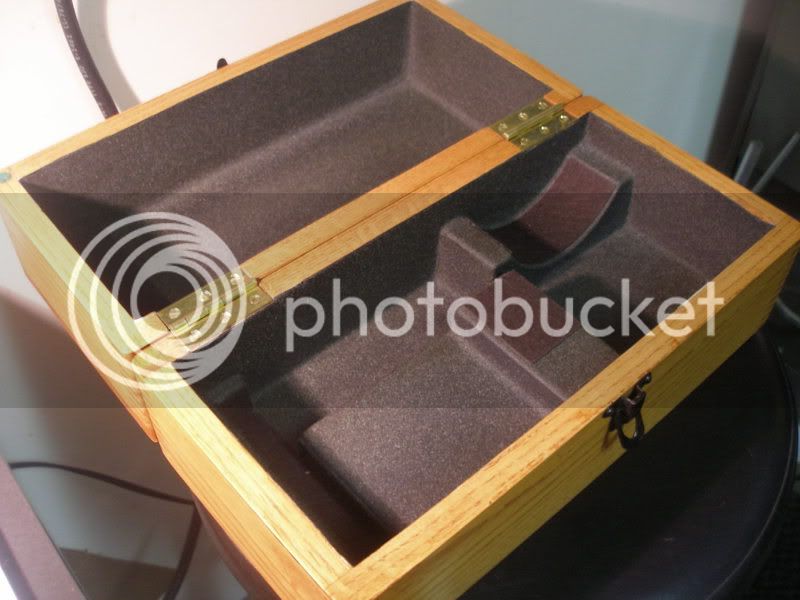
Here is the first part of my build of the Moriya Stirling Engine, originally designed by Dr.James Senft. I changed a few things alone the way, the biggest was not to build it as a fan but to put on a flywheel instead. It will have a built-in propane burner and a modified Oak box when finished.

Warning! Newbe At Work
Some operations may cause you to scratch your head ;D

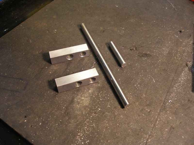
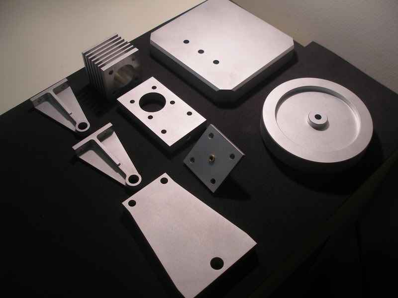
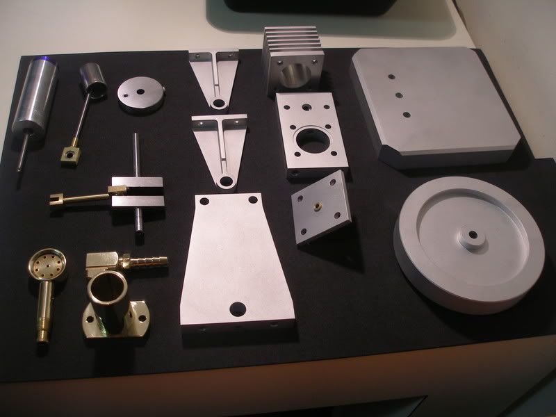
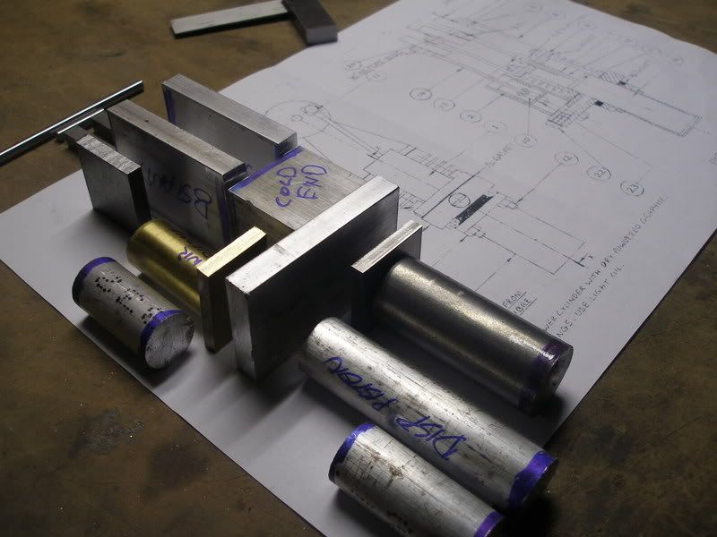
I managed to get most of the stock together before starting the project, partially because my in-house stock pile is finally gaining size and taking a proper shopping list to metal guy.
Moriya001.jpg


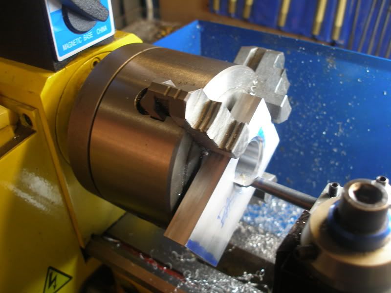
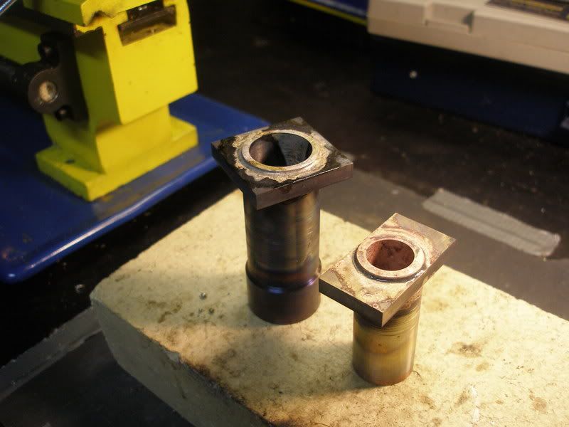
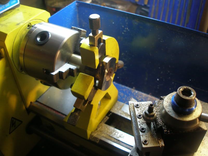
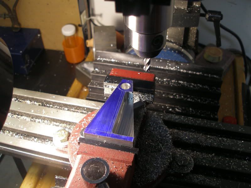
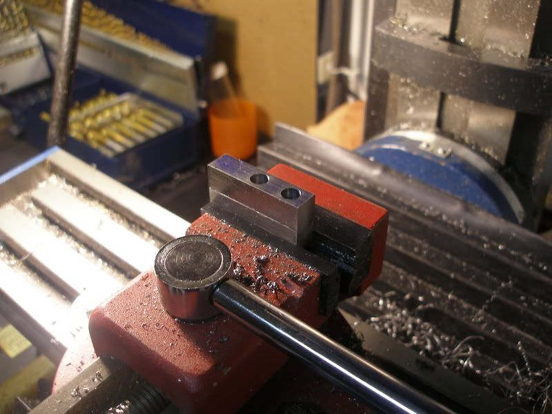
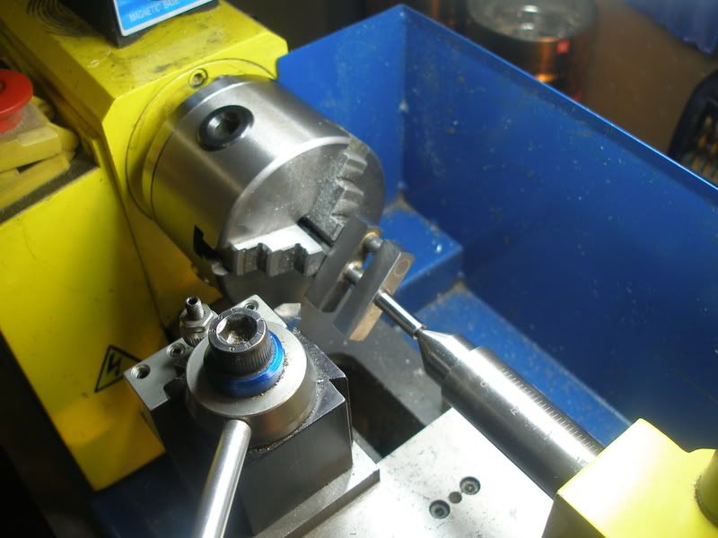
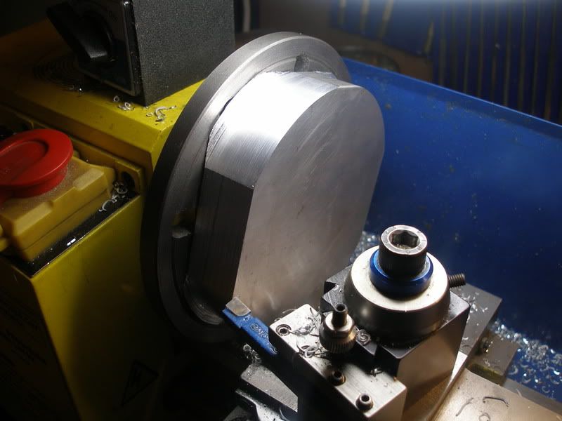
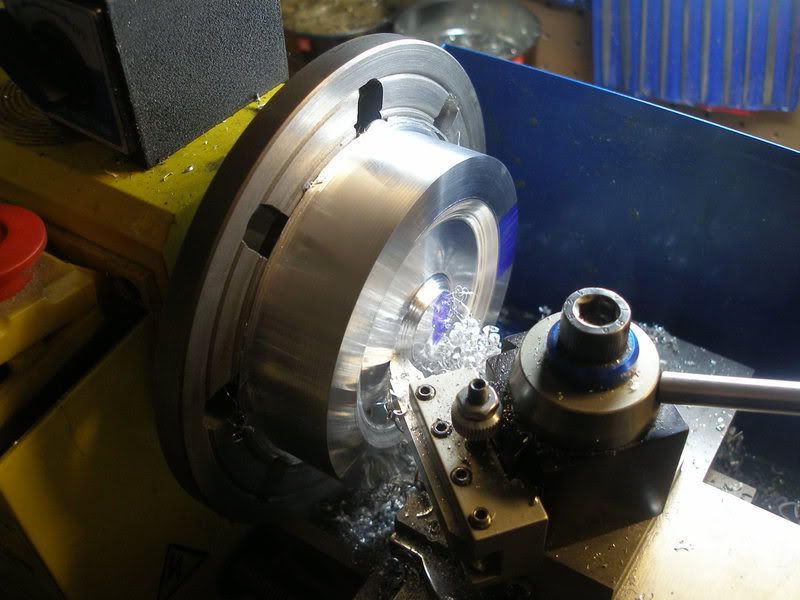
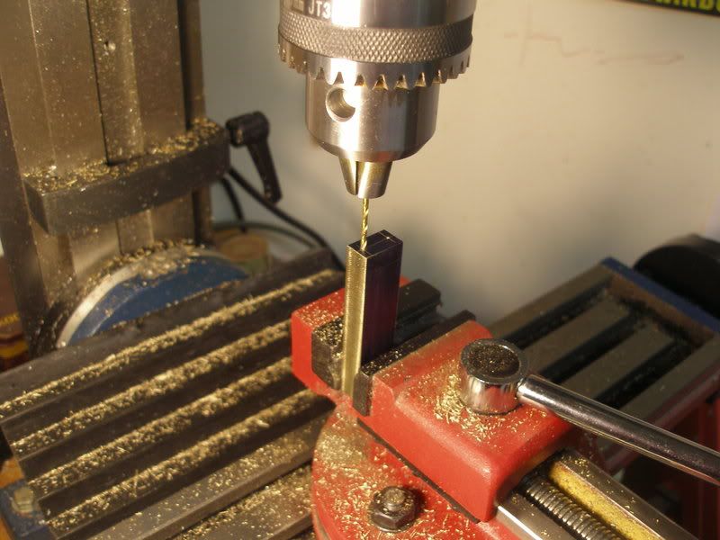
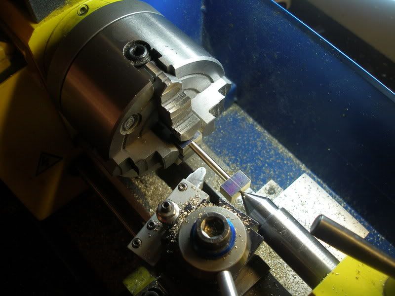
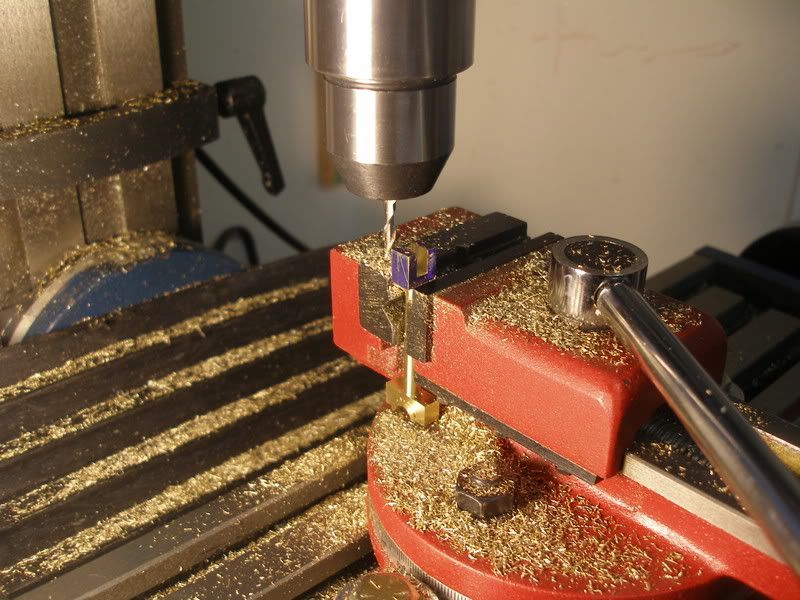
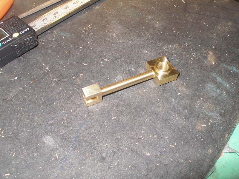
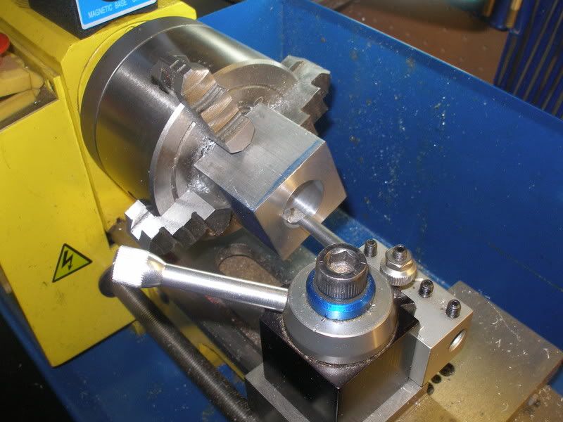
This is standard stuff, boring out the ColdEnd. The problem came about when I tried to cut the fins on the lathe. I did not have enough clearance between the 1 3/4 x 1 3/4 block and the grooving tool to work. I guess there is a lathe mod or trick for this, but I decided to do it on the mill.
AbCox08004.jpg


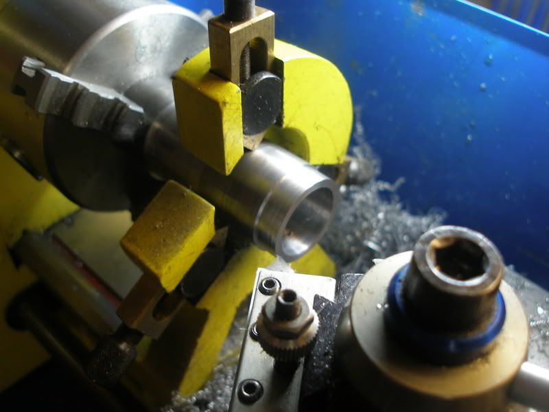
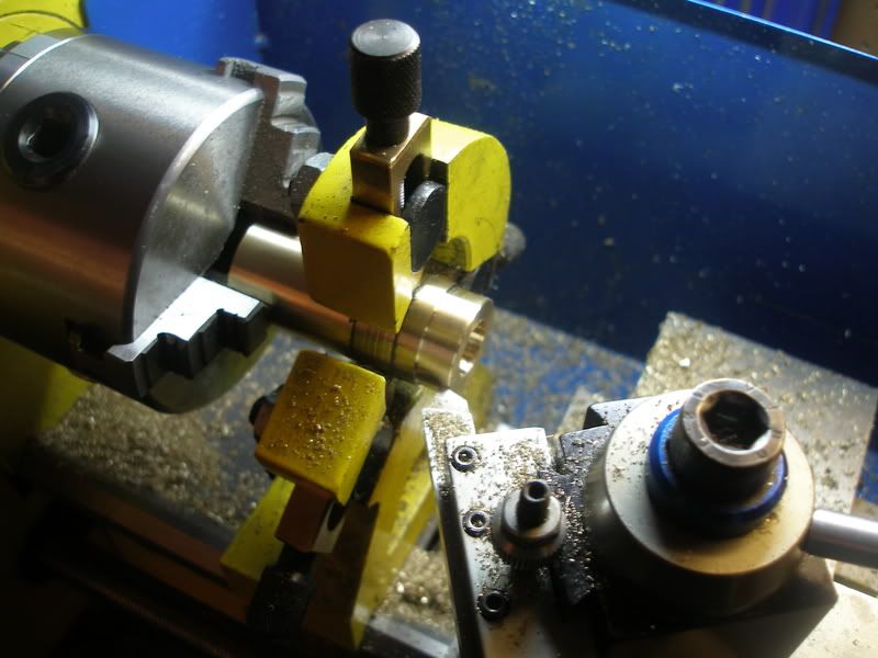
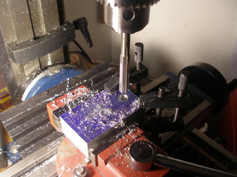
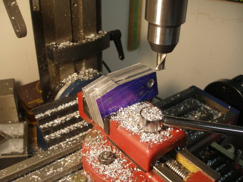
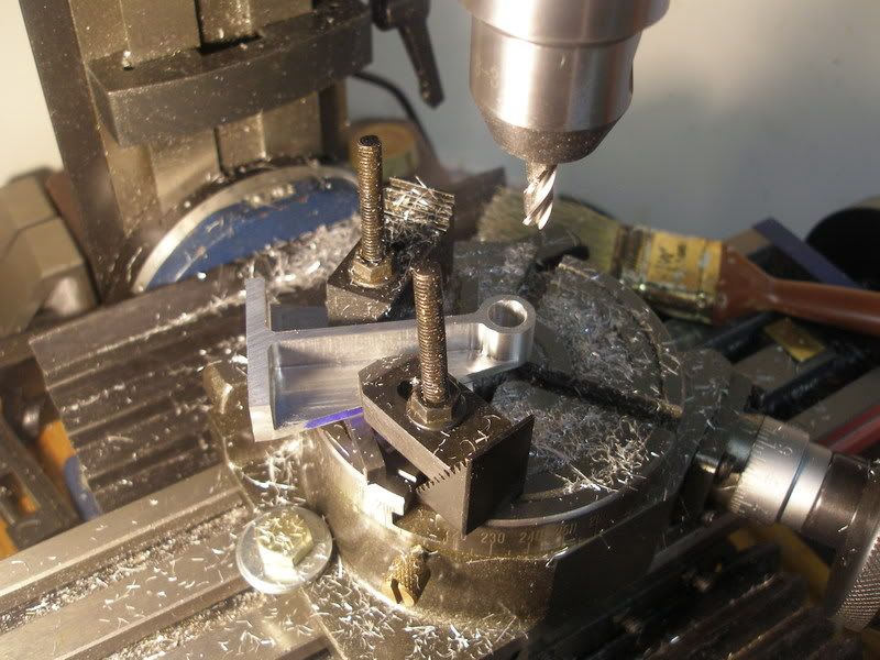
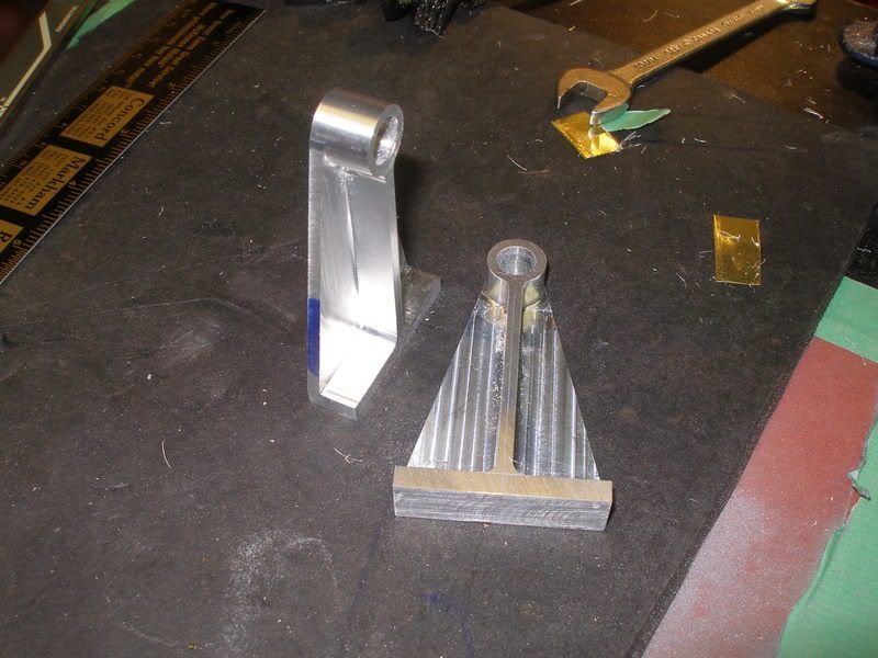
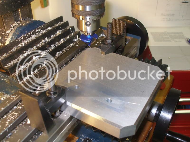
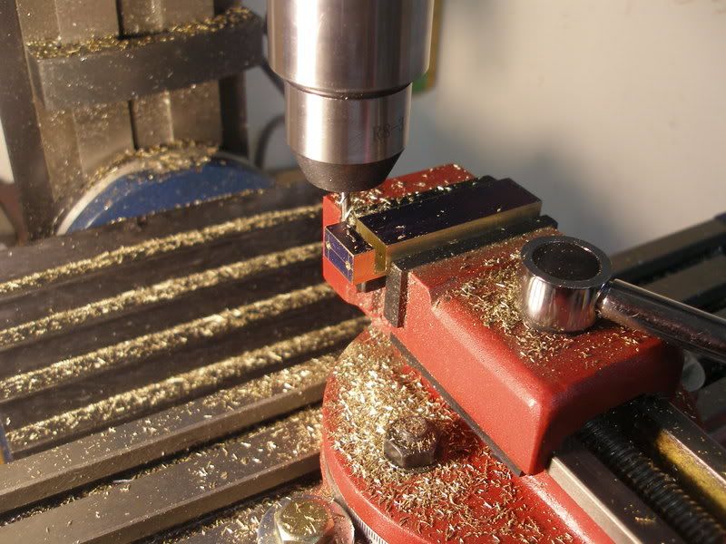
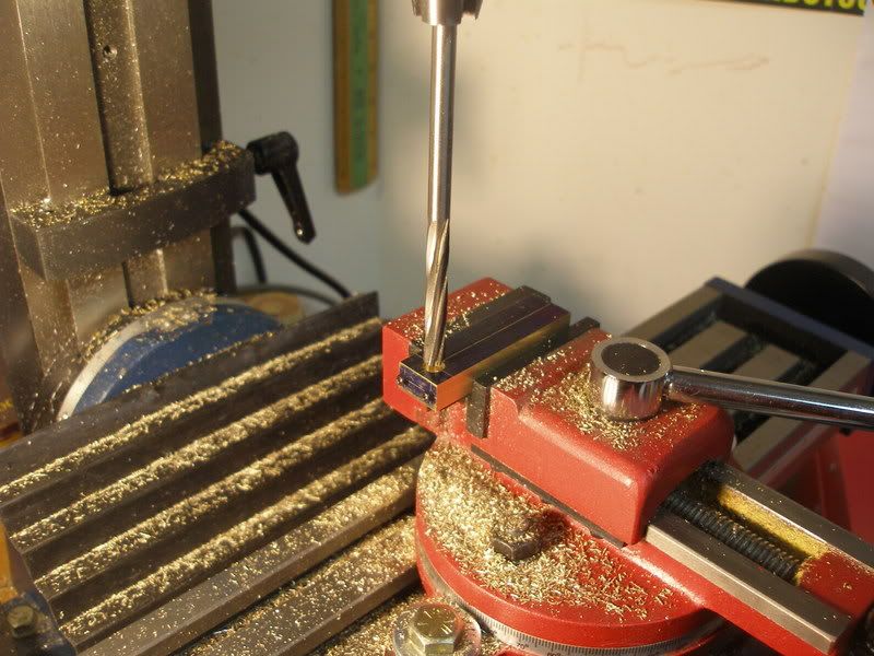
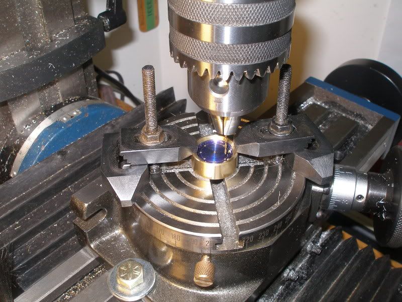
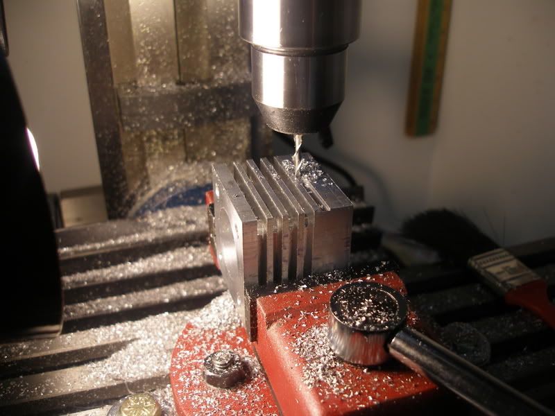
Here I am cutting the fins on the mill. I wish now that I could have done this on the lathe, this way involves a lot of passes and rotations, but it turned out OK
AbCox08025.jpg


More to come.
 
"Warning! Newbe At Work" ???

Never let on IronHorse. ;)
It's looking good to me!

Rick


Great start!

I have these plans also, this will be a good motivator.

Thanks.
 
The Moriya is a nice design. This should make for a great build to watch!

:bow:

Cheers,

BW
 
Here I am boring the offset hole and recess on the 4 jaw. Everything aligns up to this piece so it is good to get all the holes accurate. I added the recess and matching protrusion on the cylinder to help keep things straight.
Lathe005.jpg


The hot and power cylinders where bored out to 80% dia and a lip turned on the end to square up the flange plate.
Lathe012.jpg

Lathe017.jpg


The flange plates are ready to be soldered to the tubes.
lathe002.jpg


This is after silver soldering the flanges on.The mild steel soldered good and the brass was easy.I used my gas welding kit with a small tip to do the work.
lathe027.jpg


After soldering the cylinders I chucked them back in the lathe to face the ends and bore them out to final diameter. I had some trouble boring the steel one with the cheap import bars, but I picked up a "green" wheel and fixed the cutting edges up a bit.
lathe030.jpg
 
Iron Horse,

Or should I say loco(motive) ::)
1034522173.gif


Looks really good to me.
wow.gif


Best Regards
Bob
 
Just a small note: These pictures are not done in real time, I started this engine in late September and will finish it up this week............I wish I could machine that fast :big:

Here I am making the uprights. I thought I would get a bit fancy, and I don't have much luck bending Ali. I Super-Glued the two parts together, milled the sides square then drilled and reamed the hole for the crankshaft.
mill043.jpg


A bit of milling to do the angles.
nov9008.jpg


Here is the good stuff....lots of fun doing these! CNC would be so much easier!
nov9010.jpg


This is the scary stuff. I have no experience with a rotary table, but with lots of checks, it came out OK.
nov9014.jpg


Almost done, after these pictures I thinned down the top boss and angled the center support.
nov9018.jpg


Warning! Newbe At Work
Some operations may cause you to scratch your head
You don't appear as a newbe. I've already learned a couple of tricks by watching you work. I really like what you did with the supports. Keep those photos coming!
Mel
 
Now I will make the crankshaft.

I only have success at this if I solder the main webs together before drilling. On the CRS I used lead free soft solder to hold them together. I noticed that the solder does not flow very good on CRS. But I found a way that works good. First clean and flux both parts, heat, apply solder. At this point a blob will form on the surface, dip a toothpick in flux and "push" the molten blob around the CRS. The surface will now be coated "tinned" with solder. Heat both pieces again and the solder will join the two parts.

mill010.jpg


All the parts are cut and drilled, ready for soldering. I countersunk the holes slightly so the solder will make a strong joint. Drill Rod was used for the shafts.
mill011.jpg


I used Silver Solder (Hard) to join all the parts.
mill014.jpg


I put it back in the lathe to do a little cleanup.
mill018.jpg


Here is the finished part, runs true and straight.
mill021.jpg


Happy New Year

 
That is a nice crankshaft, might try one by that method!
 
Since I was using a flywheel instead of a fan blade, I felt a beefy flywheel would look best. I started with a 1" thick 5"x5" slab of Ali.
nov9029.jpg


After I finished one side, I turned it around and held the part by the inside edge to finish the other side. It was turned down to 3/4 thickness.
nov9033.jpg


This shot shows the progress so far, a few more parts to make.
nov9058.jpg
 
How did I miss this thread??

Very nice work. The engine is progressing quite nicely.

Eric
 
This part is the main base, also beefy to match the flywheel. I had heard that you could use a woodworking type router bit on Ali. So off to BusyBee for a $14, 45 degree bit. Works great, had to take it easy cause I forgot to pick up a 1/4" R8 adapter to fit the bit. I would not want to try too wide of a profile, with the 1/4" shank anyway.
dec14027.jpg


Here I am milling out the main connecting rod. First thing I did was to drill out the holes for the cap bolts. Clearance holes for the cap section and trough to the main body, then a tap was run down.
Nov16004.jpg


I do not have a saw tool, so I used a 1/8" endmill to separate the cap from the main body.
Nov16005.jpg


I assembled the rod back together with the screws and some Crazy glue, then it was a simple drill and ream operation.
Nov16007.jpg


Now the fun stuff, turning down the main shaft on the lathe.
Nov16008.jpg


I locktited the part to some drill rod and turned the side bushings. these are worth the extra time to do because they keep the rod from rubbing against the crankshaft web.
Nov16011.jpg


Here I am just finishing up the small end.
Nov16015.jpg


And the finished part.
Nov16016.jpg


Very smart, how did you get rid of the loctite? I've never used it but though that stuff was a nightmare to get off!

Also, how did you centre it in the 4 jaw to turn the shaft? Just centre pop and set that running true? How did you find turning it? Did you just have to take light cuts at first?

Cheers,

Nick
 
how did you get rid of the loctite?

I was lucky, when I removed the screws, and taped the cap it came apart and all the locktite stayed on the rod.

how did you centre it in the 4 jaw to turn the shaft?

Just with a dial indicator and some patience. I have heard some guys prefer to chuck even round material in a four jaw. I think they say it is more accurate. I am getting better at the four jaw, but prefer the 3 jaw for anything round or hex.

you may want to consider drill point end mills

Thanks those look great, I will have to order them as my walk-in places only carry basic type endmills
 
Here is one picture of the burner, unfortunately my camera died during this time and this is all I have of it. It was a bit tricky to get it working properly. I was getting a real rich orange flame. Trough lots of experimentation I found out that the size of the flame holes and the air holes have little effect on the rich flame. The biggest factor was the size of the orifice. The smallest drill I had was 0.020", so I cut the "orifice" off an old propane torch and machined it down to fit the pipe. Now I had a blue flame, but it was erratic. After some more fiddling I found the position in the pipe is very sensitive. Now it works good, low simmer to a flame thrower ;D
dec14020.jpg


I decides to give this engine an "Industrial" look, so I sandblasted all the Ali parts with a real fine glass bead. It came out with a real smooth satin finish, but every finger print showed up. I wiped it down with heavy mineral oil and it hid all existing stains and prevents new ones.
assmb029.jpg


Where I work they where throwing this old box out, so I rescued it and knew one day I would make an engine to fit it.
assmb033.jpg


I built some risers out of wood and glued them in. I was going to try and line it with felt, but that would get tricky, so I went to Home Dept and got some Rust-Oleum MultiColour/Textured paint. It goes on real nice and hides little marks and stuff. I glued some felt on only where the engine rests on.
assmb034.jpg


Most of the parts are done and waiting for assembly.
assmb045.jpg


Boy, Ironhorse, ya gotta be proud of that one! Very nice work.

Chuck
 

Latest posts

Back
Top