Krazy Klockwork Mechanism

Home Model Engine Machinist Forum

Help Support Home Model Engine Machinist Forum:

This site may earn a commission from merchant affiliate links, including eBay, Amazon, and others.

Brian Rupnow

Design Engineer
Project of the Month Winner
Joined
May 23, 2008
Messages
15,015
Reaction score
8,315
Location
Barrie, Ontario, Canada
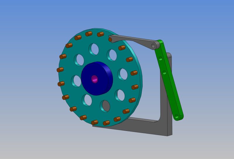
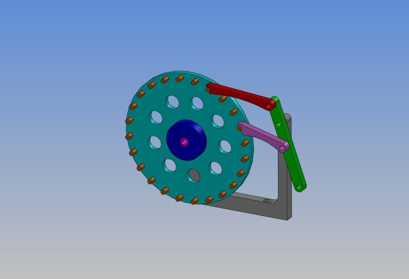
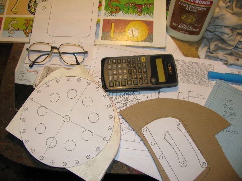
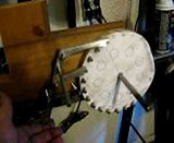
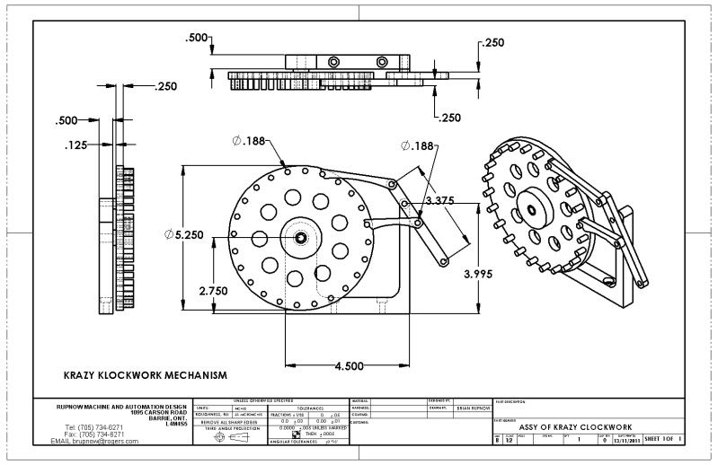
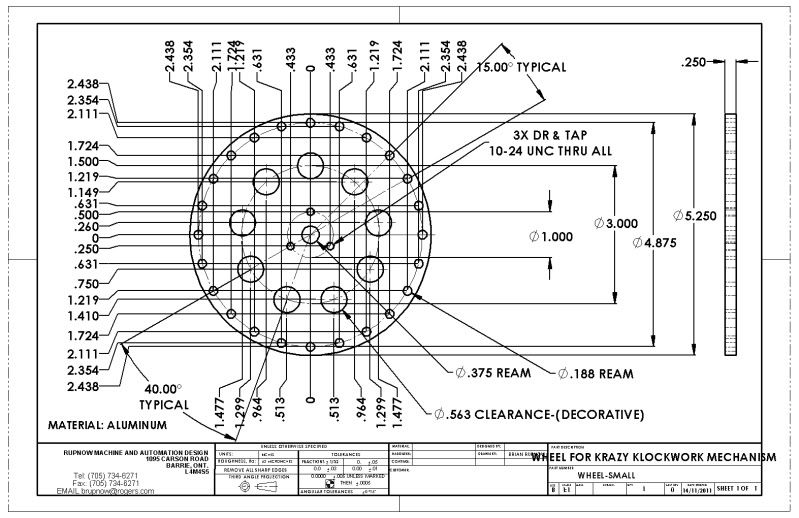
Last year for my birthday, my daughter bought me this book, "507 Mechanical Movements" by Henry T Brown. Its been a month now since I finished my build of the Popcorn engine, and I've recovered enough to start thinking about another machining project. I am always on the lookout for amusing things to run with my various collection of model steam and gasoline engines, and I may have found another. The picture on the left has a neat looking SOMETHING!!! I don't really know what its called, but it kind of looks like a clockwork mechanism, thus my threads title. I really have nothing to go on here except for the picture, and a very brief explanation of how it works in the book. As the bar "C" rocks back and forth on pivot "A", the "arms" (for lack of a better word) engage the posts on the wheel "B" and give it an "Almost continuous rotation"-----At least thats what the book says. I'm thinking an aluminum wheel about 6" in diameter, with brass "posts". I will design it first in Solidworks, and post the drawings as I go along, as usual. Driven by a small steam engine, it ought to look pretty neat!!!----Brian
CLOVKWORKPICTURE003.jpg
 
But Brian
where does the spark plug go?
Pete :big:
 
I love that book. I can't count the number of times I've gone through it.
I'm definitely looking forward to your execution of this one!
 
I love the Idea Brian, and your concept of getting your engines to 'Do' something. Looking forward to the build.

I gotsta get me that book, it looks like a great read.

The mechanism you have chosen looks like it could be adapted to a spindexer, making for extremely fast indexing simply by pulling, then pushing a lever. Something like that might make me want to use my indexer (R/T) a lot more often. It would be lightyears faster than turning the crank handle.

Kel
 
I have the same book, cover is pink though. Great book it is amazing some of the things invented towards the begining of the industrial revolution. I got my copy from Plough Book Sales for less than $10. If you like inventing things it has lots of good ideas. It will be interesting to see how you do it, how it catches the next pin after dropping down will be fun to get right.
Brock
 
Wow!!! This is difficult! Not the modeling---that took 15 minutes. The math, and geometric relationships are a real brain teaser. Since I am only going by a picture, without knowing any of the geometric inter relationships between all the parts, I arbitrarily choose a wheel diameter and number of posts, then work outward from there. Its been a long day. I have been working 4 weeks straight now on an automated infeed system for a huge metal spinning lathe that spins 8" pipe at 2300 degrees F into oxygen bottles, and my brain is a bit fried. ;D ;D
ASSY-KRAZYKLOCKWORK.jpg
 
Brain, always look down the list of who had what going on, when I see your name I see treat, one must ask between work, that fine ride, family, projects so share, you don't have time to sleep, that is when you do these things while we sleep, looking forward again, Lathe Nut
 
I THINK I got it.--Trouble is, there is no good way to animate all the movements in Solidworks, and thats a lot of metal to cut if I've got it wrong!!! I had to increase the diameter of the wheel to 7" instead of the original 6" to make room for the arms to "fall" to the next post properly. Actually, they don't fall right into place---The curved bottom portion of the arm falls onto the post, and rides on it as the wheel continues to rotate, pushed by the OTHER arm, untill the rounded hole in the bottom left end of the arm falls and engages the post. At that exact moment, the green arm reverses direction and the sequence repeats with the other arm. I think perhaps I will make it from cardboard and use stick-pins for my pivot points. One thing about doing that---If I have to move the stick-pin pivot points around a bit to make it work, I can measure the "moved" pivot points and fix up the model to match before making detail drawings. Another nice thing is that I can print my "parts" at 1:1 scale on 8 1/2" x 11" paper, and glue them to some cardboard to try this.
ASSY-KRAZYKLOCKWORK-2.jpg
 
That will look neat being driven by a small steam engine but what will this mechanism be powering? What sort of machine will require a holting rotating movement? ;D

Brock
 
Darned if I know!! My intent is that an eccentric on the steam engine will drive a link which runs to the bottom of the green pivot arm to swing it back and forth, thus driving the mechanism. The whole point here is not to do constructive work, but for the entertainment value of such a unique mechanism working. This may rank right up there with the Slinky Machine, the Pumpjack, the Bubble blowing machine, and the Piledriver..
 
;D Thm:

But you do really need to incorporate this into this 'un!
slinkymod.jpg
 
These are the parts, printed out at one to one scale and glued to heavy cardboard, except for the wheel, which is glued to a scrap of 3/4" plywood. I used the plywood,because I realized that I would probably want to be able to install a dozen or so 1/4" "posts" in it. Tomorrow I will cut everything out, mount the pieces on a plywood backing, and possibly even glue some weights to the cardboard "arms" to make things function. The wheel is 7" diameter. The arms are 3 3/8" and 2 3/8" center to center. In a way, this seems too large, and I may want to scale it down to 75% of its current size, which would leave me with a 5 1/4" diameter wheel and 3/16" posts. However, first I want to make it work, and then if I have to "revise" my Solidworks models I can easily do that. Once I have any corrections made, my software will let me scale my original models and math data to whatever percentage I want before I actually make drawings.
FULLSCALECLOCKWORKPARTS002.jpg

 
You could power a rack and stretch the arms and legs off Barbie and Ken :big:
Wind up a trebuchet!
A crossbow!
:big: :big: :big:

Brian slow down a bit you make some of us look a bit slow. Looking forward to the build.

Brock
 
Check out the movie!!! I didn't even try it with the cardboard. I have so many scraps of aluminum hanging around that I just sawed the arms out with the bandsaw from 3/8" plate. The peice of 3/4" plywood scrap wasn't quite big enough to transfer all of the wheel pattern onto, and I really regret that now. However, as a neat mechanical device, it works really well. I think the speed it can run at will be limited by the weight of the arms.--They have to have time to fall and engage the next post down on the wheel, or it gets hung up. I might try tension springs on the arms as proceed with this. What a hoot!!!
 
This is cool! I will be watching.

Mike
 

Latest posts

Back
Top