Jim builds his second v-8

Home Model Engine Machinist Forum

Help Support Home Model Engine Machinist Forum:

This site may earn a commission from merchant affiliate links, including eBay, Amazon, and others.
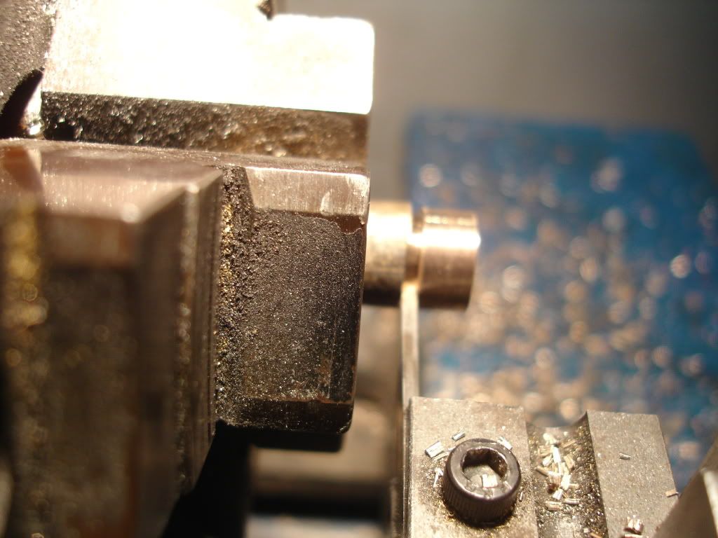
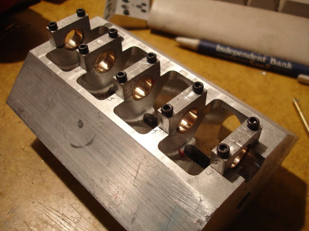
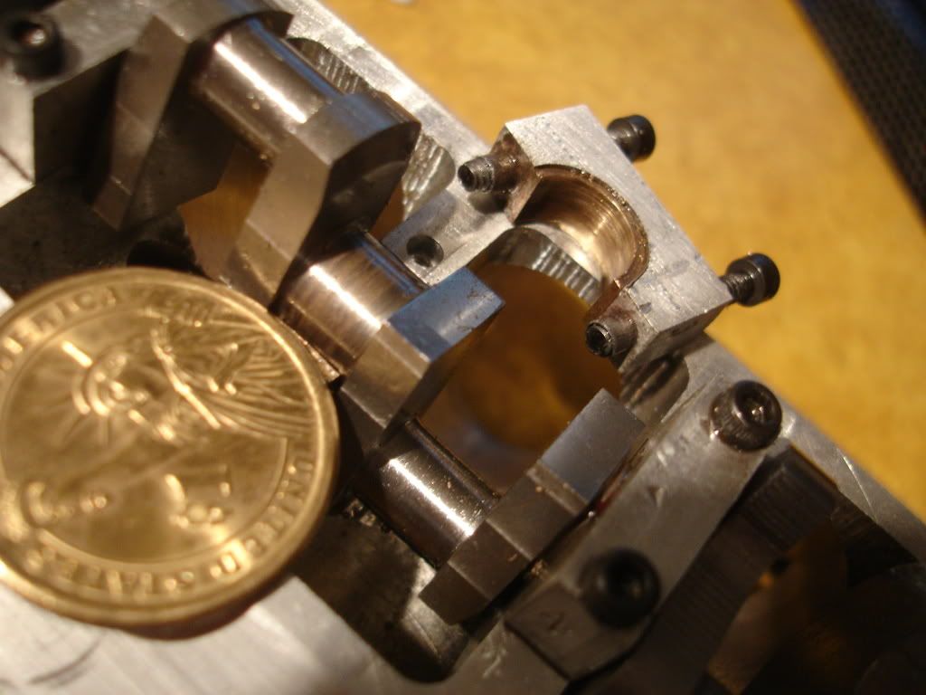
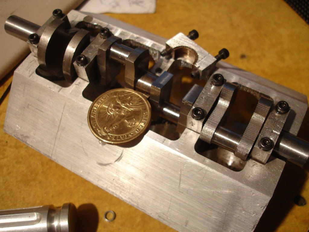
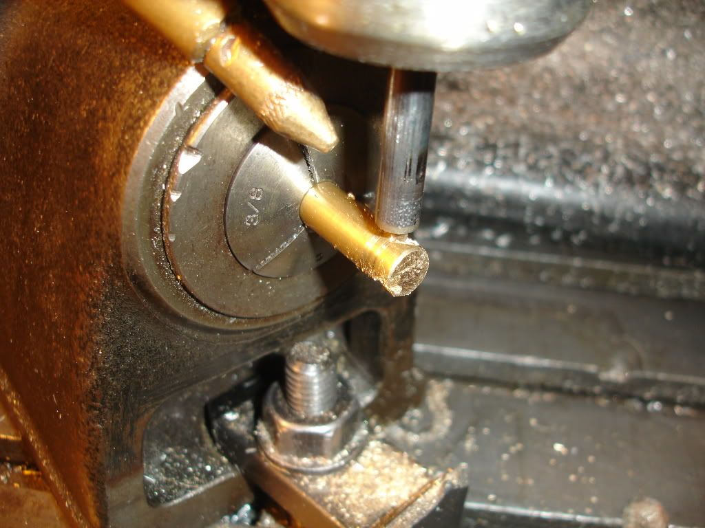
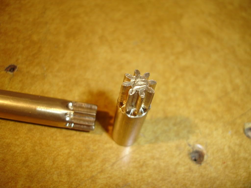
Here I'm making main bearings. I milled a piece of bearing bronze flat down the center line then placed 2 pieces of such back to back to form a bar again and mounted the combination in the lathe chuck, drilled it, reamed it, turned it and parted to length. I then spent 20 minutes searching the shop floor for the pieces after they flew off. I then owned 2 bearing shells. The next parting job was done in a paper cup. Below is a picture of the shells being parted off. Some solder them together first. I just chucked em. Seemed to work. I overheard Steve mention that's how he did it. In the past I've CNC'd them from plate. This worked better.
DSC02210.jpg
 
Here's a picture of the block with the main caps and shell locktite'd in place. I'm pretty pleased with it.
DSC02211.jpg

Next is a picture of the crank in place with one of the caps removed.
DSC02217.jpg

DSC02219.jpg
 
I used to solder the 2 pieces together but I didn't see the point so I tried it without and it works fine. Just mark it somehow before you part it off so it can go back together correctly. And boy do they fly.

At the rate you are moving, you should pass my progress by months end.

 
stevehuckss396 said:
At the rate you are moving, you should pass my progress by months end.

It helps when it's your only job.

BTW, I noted last year the Red Wing Black Birds returned on March 10th. I see this year they're late, they returned on the 12th. I'm gonna mark em tardy and dock em some bird seed.
 
Serious drool factor there. I had thought about using drill bushings in other places, but saw the prices at McMaster and dropped that idea quickly. They dont even have thinwall bushings like that, where did you get them from? I was thinking about making them from W1, but have not made anything with enough power to walk the caps yet.
 
Lakc said:
Serious drool factor there. I had thought about using drill bushings in other places, but saw the prices at McMaster and dropped that idea quickly. They dont even have thinwall bushings like that, where did you get them from? I was thinking about making them from W1, but have not made anything with enough power to walk the caps yet.
Probably overkill but I didn't want them walking around while line boring the bearings. Anyway, I chucked a piece of 1/8 drill rod in the lathe, 5c collet chuck, and drilled it with the correct size 4-40 body drill (I forgot the size but I think 0.104 dia). I then parted them off. Grind your parting tool with a slight angle so you get a sharp finish on the right side, stick a wire in the hole before parting so when they pop off they end up on the wire and your done.

The hard part for me is getting the holes in the cap accurately spaced with the holes in the block. The DRO comes in handy for jobs like this.

Thanks for the question.
 
Hi Jim,

Very nice your job!

Please, what is the bearing width in the crankshaft ?

Thanks,

Alexandre
 
Alexandre Machado said:
Hi Jim,

Very nice your job!

Please, what is the bearing width in the crankshaft ?

Thanks,

Alexandre

The bearings are 1/4 wide and 7/16 inch dia. the shells are 1/2 od and of course 7/16 id. The two end bearings are bushings and the three center bearings are shells. The rear end bearing will eventually be replaced with a flanged for thrust. The temporary bushing placed in the rear position was to help with the line boring job.
Thanks for the question.
 
Thank you Jim for your informations!

I think very cool this type project! In really, I love model internal combustion engines with multi-cylinders.

Cheers,

Alexandre
 
At the rear of the v8 there's more room on the right side. I really want to use helical distributor gears to allow me to offset the distributor to the right of the cam and forward. Helical spiral gears also provide me the opportunity to extend the distributor drive down into the crankcase to maybe drive an oil pump. So today was the day to see if I could make spiral helical gears of 3/8 OD. My plan was to first make spur gears of the required size to prove out the tool and process. I'd like to show you a picture of the tool making program but due to a power failure in the area I lost it before I had a chance to save it so I'll just tell you about my procress.

I made the cutter by first using a feature of the program to generate a profile of the gear. I designed it with an even number of teeth so my spindex could index the cutting process. I copyed the shape of the space between two teeth to generate the profile for the cutter. Using that profile I revolved a surface around the center line. I then stood a short piece of drill rod vertical in the milling vise and CNC'd the surface on the end of the rod. I next layed the rod horizontal and milled it half away for a distance. This picture might make it more clear. Keep in mind, this cutter is chippedat the tip. It worked well though for quite a while.
DSC02228.jpg
 
The next step was to use the tool in the spindex to machine some teeth. This picture shows the process after I turned the spindex 45 degrees for helical gears but you get to see my spindex and setup. I intended to make a second pair of gears for pictures but for reasons which I'll explain later I don't have those pictues.
DSC02223.jpg

So after all that I milled a couple of spur gears. They really mesh smoothly.
DSC02226.jpg
 
I then slid the spindex 45 degrees and machined a couple of spiral gears. Now I know the tool should follow the helix. I don't have a 4th axis and what with the gear width being only 1/4 inch or so I decided to give it a try. I must say I was extremely pleased with the way the gears meshed. I made a test setup by drilling 2 right angle offset holes in a block and driving the gears for a while. Unfortunately I stressed them too much and stripped them. I'm gonna make another pair.

Then we had a general power failure and when the power came back on my mill electronics was toasted. I think I'm done for a while. :mad:
 
Hi Jim,

Very cool!

But... how do you specified the geometry for make the cutter tool ?

For example:

The crankshaft and camshaft... we know that the camshaft need to rotate once for every two laps of the crankshaft. So... there is also a distance between both and the diameter of each gear depends of size and geometry of the teeth... okay ?

Maybe would be better ask... How define the geometry of the teeth...

There is better some form to understand this ?

Thank you,

Alexandre
 
jpeter said:
Now I know the tool should follow the helix. I don't have a 4th axis and what with the gear width being only 1/4 inch or so I decided to give it a try. I must say I was extremely pleased with the way the gears meshed.

I had always thought thats how it worked, as thats always been the most confusing part of it for me. Thanks for posting that.
Then we had a general power failure and when the power came back on my mill electronics was toasted. I think I'm done for a while. :mad:
Thats been happening quite a lot around here lately. :mad: Sorry about the mill electronics.

Alexandre Machado said:
There is better some form to understand this ?

Not wanting to thread hijack, but go here: http://www.modelenginenews.org/
On the menu bar on the left, expand the resources tab and click on How to ?, follow that to skew gears.


But Jim, by all means, please expand on your methods. For this type of complicated machining, the more explanations the better the chances of something sinking in.
 
Alexandre Machado said:
Hi Jim,

Very cool!

But... how do you specified the geometry for make the cutter tool ?

For example:

The crankshaft and camshaft... we know that the camshaft need to rotate once for every two laps of the crankshaft. So... there is also a distance between both and the diameter of each gear depends of size and geometry of the teeth... okay ?
Maybe would be better ask... How define the geometry of the teeth...
The gears in previous post are to drive the distributor from the cam. To answer your question though, I designed the distance between the crank centerline and the cam centerline 1 inch. That being the case, the pitch diameter of the crank spur gear needs to be 0.666... inches and the gear on the cam needs a pitch diameter of 0.666..X2 or 1.333... inches. Profile? I have a computer program to create the desired profiles. There are way though to do it manally. The tooth profile is close to an arc so cutters can be shaped with an end mill or a fly cutter of the proper size and will work well enough.
 
stevehuckss396 said:
Are you only making one of these engines or two?

You know I have a birthday coming up! At the rate you are moving It should be done in time.
You're the guy who makes 2 or more at a time. You're ahead of me and you're making 3, with blowers and carburetors yet. I'm in a hurry cuz I'm an old man and starting to realize I have only limited time left. :) And besides, I have to get done before the Japanese neutrons arrives.
 
Okay Jim!

I understand... What's the computer program that you use for this? Is not a common CAD program, correct ?

Jeff, thank you too! I found the informations.

Alexandre
 
So I'm told necessity is the mother of invention. I think it worked out here cuz I needed to get my mill back running. After a little trouble shooting I found one of the low power power supplies had taken a dump. I ordered a new power supply off ebay but but who knows how long it will be getting here. What I did today was hook up an old ATX computer supply in temporary fashion. Here's a picture of the lash up. It's work'n. I'm happy. My insurance man said he'd buy me a new one but I haven't yet decided if my soul could stand the required dishonesty. Involved would be lying to him about not being able to find anyone able to fix it. A new drive though full of Gecko drives would be nice. We'll see.
DSC02231.jpg
 
Back
Top