Jim builds his second v-8

Home Model Engine Machinist Forum

Help Support Home Model Engine Machinist Forum:

This site may earn a commission from merchant affiliate links, including eBay, Amazon, and others.
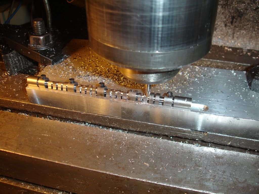
Milling the top side.
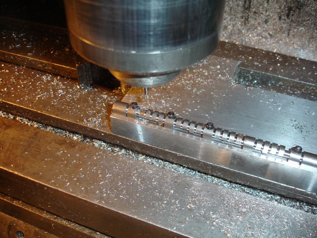
DSC02122.jpg

It's been flipped.
DSC02123.jpg

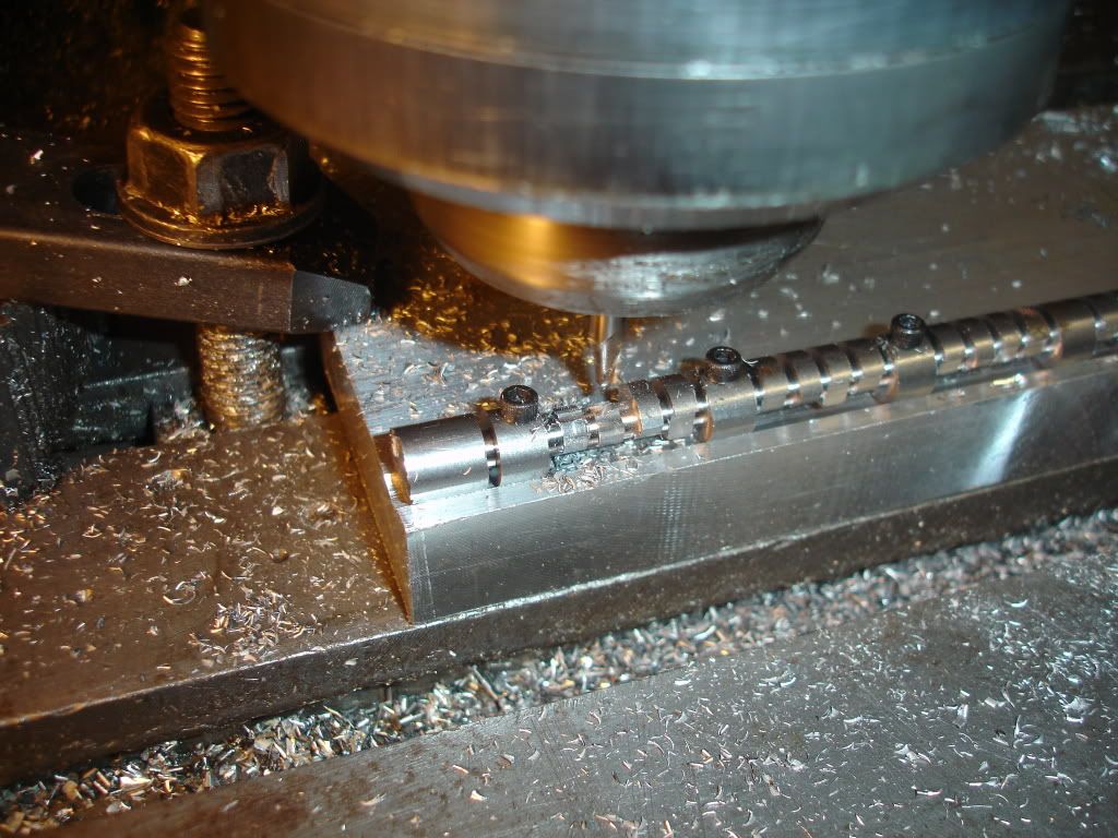
Here I'm milling the bottom side. I don't know where the remaining two screws are. I'll surly get them in by the time I get that far. It takes about an hour to mill a side. This is the third try for this cam. I was having trouble getting the sides to register. The trouble turned out to be my cheap 3/16 collet had the hole off center such that the cutter was running out by .007. I bought a new American made collet and my troubles cleared up.
DSC02125.jpg
 
Fantastic, I have never seen a cam made that way. Great method.
 
Peter, that`s a weird way of making a cam!
I love it!
Did you made it by hand or with CNC?

Cheers,
Norberto
 
LongRat said:
Fantastic, I have never seen a cam made that way. Great method.

I don't think anyone else has either. Maybe I'll start a new fad. Thanks for the compliment.
 
CNC'd it. I think thou if you could draw it you could read the g code and do it manually. I'd take some time though. If you knew the math you could generate the coordinates with a spread sheet and do it manually that way too.
 
Its hard to accomplish much while traveling in Florida. The wife and I took a trip to watch the space shuttle launch. We heard a radio story about Discovery launching for the last time and decided to back the motorhome out of the garage and head south to see it. What a spectacular event to view from up close. I suggest everyone who can catch one these last few last launches. The 80 to 85 degree days were nice too.

Anyway, I've gotten back home to more important stuff, the v8 build. It was time to make some cylinders. I first turned 8 blanks from cast iron purchased from McMaster-Carr.
DSC02181.jpg


After parting off the slugs I chucked them in a collet and faced the rim to the right thickness, 0.0312. Turned the flange to the proper diameter too, 1 inch.
DSC02182.jpg

 
I drilled each slug to provide clearance boring bar.
Boring is next.
DSC02185.jpg

 
I've got the boring bar set up. I'm trying to hit 0.745.
DSC02187.jpg
 
Here we go. These cylinders came off the lathe at nominal 0.745 but with a 0.001 taper and some out of roundness. I think I squeezed them a little too tight in the collet. I must add, I made the collet adaptor nose piece. It runs true too but I'm beginning to wonder is it's truly round. I outta check that.
DSC02186.jpg
 
If I had a Sunnen hone I'd hone these cylinders but I don't so I'm going to lap them. Here is a picture of my home made 3/4 lap.
DSC02188.jpg

Next is a picture of the lap being adjusted. In the background is my small hole gage style of hole gage I use to determin the condition of the cylinder.
DSC02190.jpg

I'm at the drill press lapping like a puppy. I once acquired a three gallon pail of 120 grit clover compound so its what I use. Each session removes maybe 0.0002 from the diameter so just to get out the taper will take 10 adjustments of the lap. Its gonna take some time to complete all 8. BTW, the drillpress table came with all those extra holes.
DSC02189.jpg
 
I was wondering why cast iron? Are you going to use cast iron pistons? Iron/Iron is a good combo.

I usually use steel liner/aluminum piston. I like the aluminum piston because it reduces the reciprocating mass. I'll gab at ya Wednesday.
 
Hey Steve, good question. I like cast cuz its easy to machine and lap and it holds oil well. Steel would be good too. Maybe 12l14? Basically I've always used cast and never acturally considered any other materials. Maybe I should. I'll be there Wed..
 
jpeter said:
Hey Steve, good question. I like cast cuz its easy to machine and lap and it holds oil well. Steel would be good too. Maybe 12l14? Basically I've always used cast and never acturally considered any other materials. Maybe I should. I'll be there Wed..


I'll bring my block. I used 12L14 and the finish is awesome. You can try it on the next V8! ;D
 
Is there a reason (bar doesn't fit through spindle?) you didn't machine the liner in one setup from bar and cut it off? It seems this would prevent any issues with squeezing the liner and alignment a second operation might bring?

Looking great!!
 
dieselpilot said:
Is there a reason (bar doesn't fit through spindle?) you didn't machine the liner in one setup from bar and cut it off? It seems this would prevent any issues with squeezing the liner and alignment a second operation might bring?

Mainly, I don't like drilling and boring blind holes. I wasn't too terribly concerned about concentricity, the major purpose of not unchucking the bar between operations.

Your point though is a good one.

The bar was about 2 ft long and when I was turning the outside of the sleeve I could feel some shake in the lathe. I'm wondering if the outside of the sleeve is out of round because of the imbalance during the turning of the outside. If that were the case, squeezing the sleeve in the collet would transfer that out of roundness to the inside during the boring. I'm only talking about a few tenths.
 
It's just me then. I'm not scared of boring blind holes anymore. I just bored two sets of holes 1.5", 1.9" diameter 5.5" deep, and .433" diameter 2.5" deep. Parting a thin wall like that is a cakewalk as well.

I use a spindle spider if the bar is long enough.
 

Latest posts

Back
Top