Jim builds his second v-8

Home Model Engine Machinist Forum

Help Support Home Model Engine Machinist Forum:

This site may earn a commission from merchant affiliate links, including eBay, Amazon, and others.

jpeter

Well-Known Member
Joined
Aug 6, 2010
Messages
464
Reaction score
39
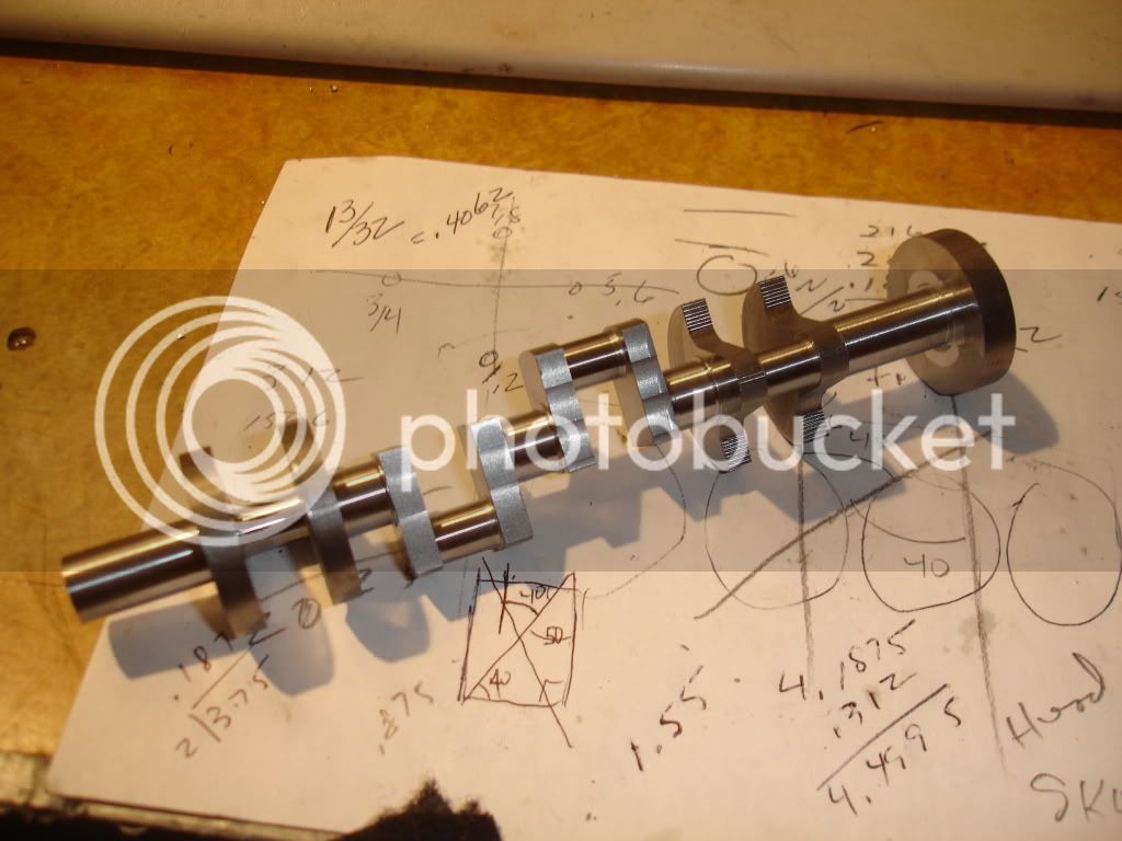
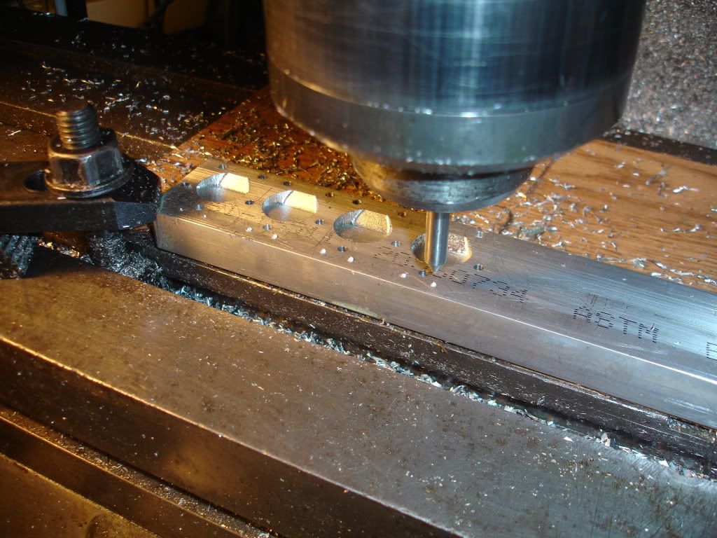
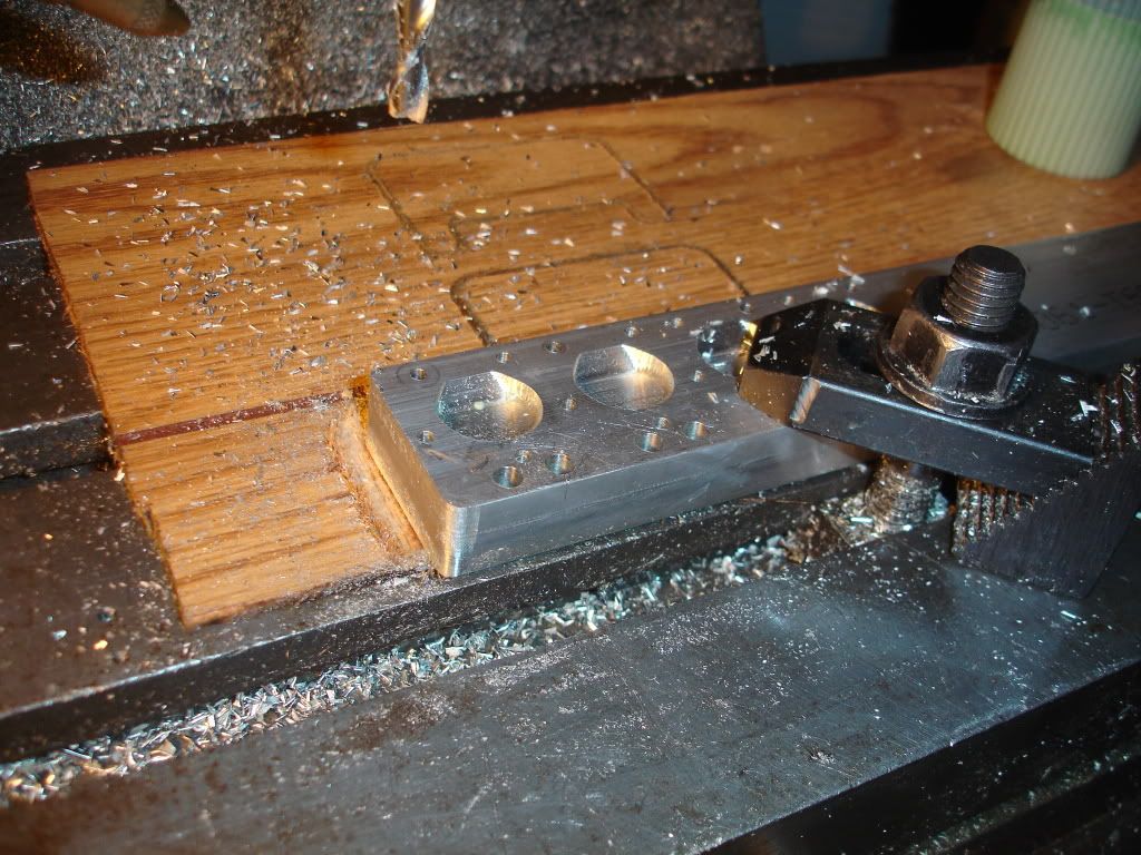
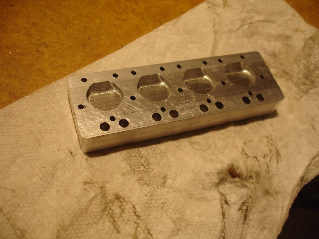
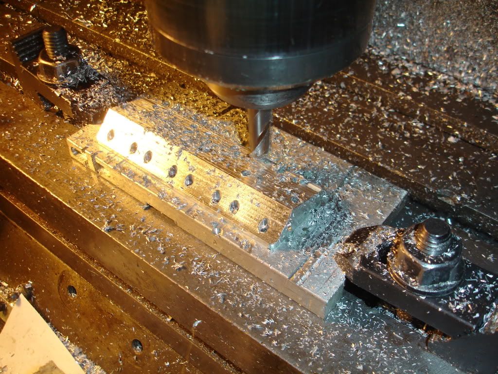
Seems like its time to build another v-8. The last one and the only other one I've built runs well but is missing some features I'd like it to have. It's shy a cooling system, water pump and a lube system. You ask why I just don't add these items. Well I want it running cuz I often start it just to hear it run and too, I like to show it off and I can't do that if it's torn down. It seems like a lot of work building a second v-8 but I'm retired and have to do something with my time, so why not.
 
The plan was started December 10, 2010. I wanted it to be smaller than the first. This v-8 as designed will have a 3/4 bore and matching stroke. The first part I decided to make was the crank. I started making chips around Xmas. I got the crank generally complete. Here's some pics of the progress. This pic shows me blanking out the crank by clamping it in a t-slot groove. What you can't see is flats I've milled on each end which I used for indexing the blank while standing it up in the vise for drilling. I'm milling away as much material as reasonable.
DSC02102.jpg

Notice the 5 centerbores in the end. The hidden end has similar centerbores.
 
I'm still milling. I got about 4 hours into blanking out the crank.
DSC02104.jpg

You might notice a few notches on the clamps. I hope none of you do that.
DSC02106.jpg

Still milling.
DSC02109.jpg

Pretty much blanked out.
 
Its time to mount it in the lathe. I first placed a piece of bar in the chuck and turned a live center. I have a live center that fits in the spindle taper but I like the chuck idea cuz I think its more accurate, less likely to wobble.
DSC02111.jpg

I rough in the main first.
DSC02110.jpg

Next I turned the throw pins to final size. The tool looks like a parting tool and it is but its been ground to more resemble a turning tool. The corners have been broken. Having a chamfer in the corners strengthens the crank. I'll releave the rods to allow for the chamfer.

 
Gotta check out the throw pin diameters. I got lucky, they're all on the money. These are 5/16 - 0.002 to 0.003.
DSC02112.jpg

Got all the bearings turned. I kept the mains 7/16 exactly. I want to use standard bushing for mains.

 
Regarding feathers, damn good question. I'm gonna feather my features. What was I thinking.
 
It's time to stylize the end throws so here I am, back at the mills.
DSC02113.jpg
DSC02114.jpg

Got one end done.
 
Getting close to finished. Time to check out the work.

The center main is within a thou. That's close enough for government work.
DSC02135.jpg

This is the final product until I get the block done. Took me about 14 hours.
 
Hi Jim
Very nice work on the crank. What are you using for steel? It looks like it cuts pretty nicely. It's good to see someone else does stepping off with a ball mill. Are you working from a drawing or just freelancing it?
George
 
George, it's 12L14 steel. I've ruined too many tools to use strange steel. Not freehanding, Its all been planned out. Did I understand your question? Thanks for the question. BTW, we're due for 12 inches of snow here tonight. That'll keep me in the shop for a day or two.
 

Nice work Jim!

I've been itchin' to try a V-8, I'll be following along closely.

 
Hi jim
V8's rule ;D
Pete
 
Great to see another V8 build, Jim. Great looking crank, and I'm looking forward to seeing your progress.
 
I've made a few more parts but I've got a lot yet to make. In this series I'm going to showcase making the heads. Keep in mind there are two to make. I'm only showing pictures for one. The head is about 4-1/2 inches long and the combustion chambers are 1-1/16 apart, center to center. The bore measures 3/4 dia. The first picture shows me pocketing out the combustion chambers. They were tricky cuz I had to include a wall to provide for the 1/4-32 sparkplug. BTW, for another project I bought a bunch of them from a local autoparts company, Advance Auto Parts, for $12.50 ea. Had to order them. Took a day.
DSC02082.jpg


Next, I'm spot drilling holes for the pushrods. These heads sure have lots of holes.
DSC02085.jpg
. Here I'm drilling the holes for the pushrods.
DSC02084.jpg


I noticed in the pic the head bolt holes are already drilled. I must have missed taking a picture of that process. The head bolts are symetrical arranged so 2 cylinders share one common bolt.

Here's the combustion chamber side with all the holes drilled, sans plug holes.

DSC02088.jpg


The process of counterboring the head bolts is not shown in any pictures but in the next picture you can see it's been done. I used a standard design but home made counter bore. The pilot on the end of the counterbore helps me control the depth. I did it in my drill press. It this picture I'm surfacing the top surfaces. I'm using a 1/2 inch ball end mill, shooting for sclape height of 0.0005. The ball end mill provides the fillet. Surfacing the faces works well cuz I don't have a lota luck using the sine plate. I don't own a set of gage blocks.
DSC02091.jpg
Here's another view.

DSC02092.jpg
 
Back to the combustion chamber side.
I cleaned up the site for the valves. The top side of the head is parallel to the top of the combustion chamber so bolting the head down to the top side gets the combustion chamber roof angled correctly. My plan is to cut the seat right in the aluminum. I've done this before. It works well for me.
DSC02095-Copy.jpg

Here I'm reaming the holes for the guides, 0.250.
DSC02096.jpg


I need intake passageways. Notice I bolted the head to an angle block. The proper angle came from cad drawings. I created a workplane through the passageway centerlines. Then created a block such that the workplane was parallel to solid jaw of the vise. Then, no matter how I turn the head in the vise the workplane is always vertical. At least, thats the plan. Seems to work.
DSC02097-Copy.jpg

I need some sparkplug holes too. For spotting soft metal like aluminum or brass I often spot with a pointed, hardened piece of drill rod. I outta buy some spotting drills.
DSC02099.jpg

Here's another picture of me using a homemade angle block. Hard to see here but I'm drilling an exhaust passage.
DSC02100.jpg


Great stuff.
What are you using for path generation? The combustion chambers in particular look very nice.
 
Back
Top