Jim builds his second v-8

Home Model Engine Machinist Forum

Help Support Home Model Engine Machinist Forum:

This site may earn a commission from merchant affiliate links, including eBay, Amazon, and others.
Hi Jim,
Did I understand you correct, you bought 1/4-32 spark plugs from the local auto parts store?
George
 
Got a pair. Put some valves in just for fun. I'm trying to keep the valve stems short so the covers don't have to be too tall yet I need room for the springs, spring covers and the guide washer base needs room too. When ever I used c-clips for valve retainers I've recessed them in the cover to kinda trap them in. Notice I didn't do that here. Anyone had any experience with non-trapped c-clips popping off?
Hey George, NGK 1/4-32 plugs from Advance Auto Parts for $14 ea. a couple of years ago. They had to order them. It took a day.

DSC02152.jpg
 
Regarding the plug price. I noticed I posted a couple of different prices. The truth is I don't actually remember what I paid other than the price was under $15 ea. I've bought lots of them, maybe 25 over the last few years.
 
Hey, I'm still working on the heads. Seems like itnever ends. Here's a picture showing a few valve guides. These were turned from 5/16 brass on my Sheldon w56 lathe.
DSC02130.jpg

Also shown are the springs I intend to use; 0.023 wire. I plan to cut them in half. Bought them off e-bay.
Need some spring cap too.
DSC02156.jpg

Didn't have the proper size bore for the caps so I cnc'd the bore. That helpe me control the depth too. Shown is the fixture I built to hold them while I pocketed them out. Worked well.
DSC02154.jpg
 
Looking really good. Loving all the pics that you are taking. Always enjoy the mini v8 builds.
 
This is a screen shot profile of my head plan. I could have printed a jpg image but the camera was handy so I just took a shot of the screen.
DSC02158.jpg

Here I'm making some rocker arms. I've got 8 holes so I'll have 8 rockers.
DSC02153-1.jpg

I'm going to have to drill and tap each rocker for a set screw for setting the valve lash. In this pic I'm fashioning a fixture to hold the rocker for the drilling operation.
DSC02159.jpg
 
No name yet but I'm open for suggestions.
You know, you were the guy who said I messed up when I didn't document the the first build. Hopefully I'm I doing a better job on this one. I must admit its fun.
 
jpeter said:
No name yet but I'm open for suggestions.
You know, you were the guy who said I messed up when I didn't document the the first build. Hopefully I'm I doing a better job on this one. I must admit its fun.


Did I really say "messed up"?

I didn't call you names did I? Haahahaha!!!

I'll see you Wednesday. Also bought a 1/16 parting blade today.
 
Every v8 needs a cam. It was time to start that daunting project. After a period of time with pencil and paper stressing the few brain cells I've left I booted the computer and layed it out. The following picture is a screen shot of the cam with the lobes surfaced.
DSC02171.jpg

I next had to create some tool paths. Here's a second screen shot showing essentially the same view but showing tool paths for surfacing the lobes.
DSC02170.jpg
 
I find the cam is less likely to warp if I blank it out first. I like turning these kind of projects between centers but the cam is quit wimpy for that work so I chucked it in a collet. I'm using a 1/16 parting blade.

BTW, the collet chuck was a previous project. I made the nose piece from solid bar. I had some work involved getting it accurately tapered. During the project I bought a cheap tapered sleeve to convert into a nose piece but what I found was the one I was making was a better fit than the Chinese one. The drawbar, not shown or course, was made from a piece of 1 inch black iron pipe. This collet chuck is the greatest addition I ever made for my lathe.

I made the tool post too. It from Home Shop Machinist plans from a few years ago. It's an excellent design, works really well and was easy to build. Here's the cam getting blanked out from 3/8 round bar.
DSC02120.jpg
 
Hi Jim,

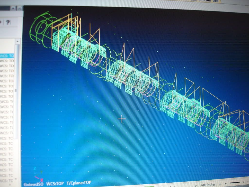
Compliments for the build, looks very good! I hope in future to be able to generate 3D milling paths too, for now I do all in the 2D world.

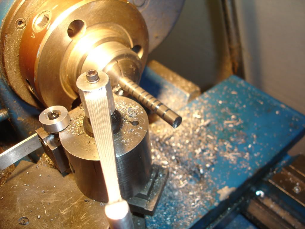
I like your collet holder, and planning to make one myself too. About the drawbar, did you use any bearing on the end? In my idea a pressure bearing will make it a lot more easy to tighten the collet in the main spindle of the lathe. I am curious to learn about your experiance.

Keep the progress coming, its a pleasure to read.

Regards Jeroen
 
For a bearing I used a brass coupling and two pieces of pipe. I locktited the threads. I could have used a steel coupling and brass washer. If I was to do it again I'd use a brass bushing instead of a coupling cuz the pipes don't remain straight in the coupling giving me some out-of-balance condition from the wobble. I had a 5 or 6 inch pulley laying around I used for a hand wheel. I don't have any trouble tightening it up enough. Not including the collets I got under $10.00 into it. Runout is pretty small if I'm careful when I seat the nose piece. It's hard to measure runout cuz collets are not always perfect and chips get under stuff more than you'd think but if I'm really careful I can measure under a thou.
 
I'm looking forward to seeing a pic of those toolpaths being run on your mill - I assume in 4th axis mode. Planning to grind cams individually in the XY plane myself, then secure onto a plain shaft with set screws.
 
Hello Jim!

First, Is very cool your job and your design !!!

I have some doubts...

What CAD program do you use ?

What is the diameter of the intake and exhaust valves ?

The diameter of the cylinder is 3/8", correct ? That is less of the one centimeter... that is very crazy! :) But very, very cool !!!

Thank you for share your project with us!

Alexandre
 
Thanks for the explenation Jim! I will see what I can find layin around in the scrapboxes and give it a try.

Regards Jeroen
 
This engine is a little bigger than 3/8 bore. Its a square engine 3/4 inch bore and 3/4 stroke. The cylinders are 1.0625 inches apart and the block is going to be made from 2.5 inch square aluminum. The block length is going to be slightly less than 5 inches. Regarding the valves, they mic out at 0.270.
 
DSC02121.jpg

Back to work on the cam. I clamped a block on the mill table, then milled a groove along the x axis for a saddle for mounting the cam blank. Then, I drilled the cam blank at the 5 bearing sites for 4-40 screws to bolt the blank down. I find it important to hold the blank straight while I'm machining it. These bolts and holes also index it when I do the other side. To machine the bottom half I just unbolt it, rotate it a half turn and bolt it back down. I don't expect the holes to effect the bearings much.
 

Latest posts

Back
Top