Jim builds his second v-8

Home Model Engine Machinist Forum

Help Support Home Model Engine Machinist Forum:

This site may earn a commission from merchant affiliate links, including eBay, Amazon, and others.
Spindle spider, whats that like? Is that like a bushing with a set screw or something to keep the stock centered?.
 
hey Guys, do me a favor and check out my buddy's cute little 4-stroke. It's on youtube.
here's the link. Give him some hits and see a fine little one lunger in the deal. Pay attention to the knife and fork rocker arrangement. If you have a good connection view it in HD.
[ame]http://www.youtube.com/watch?v=cXwa49PLX7Y[/ame]
 
I got started on the block. The block is 2-1/2 square by about 4-3/4 long. I used 2-1/2 inch square stock and first had to square up the ends. I c-clamped it to an angle block and then dialed all the sides to make sure the block was vertical.
DSC02191.jpg


Because so many features are related to the cam position I decided to next drill the cam tunnel. Drilling a hole that deep has always been a challenge for me. I posted a querry on the forum about how to drill a deep hole straight and true. I got a lot of guesses but not much qualified real help. I googled the question and found whats referred to as a d-bit. Apparently it's the original gun drill. They're easy to make so I made one, drilled a test hole and was shocked at the results. I drilled a test hole in a 5 inch block with my homemade d-bit and got a hole that was accurate, straight and exited where it was supposed to. Try it, you'll like it. Just google d bit.
I drilled for the cam using the same setup I used for finishing the end.
 
jpeter said:
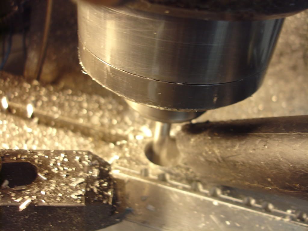
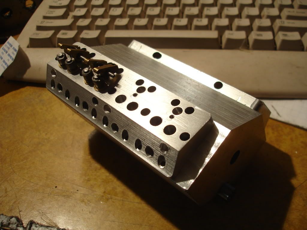
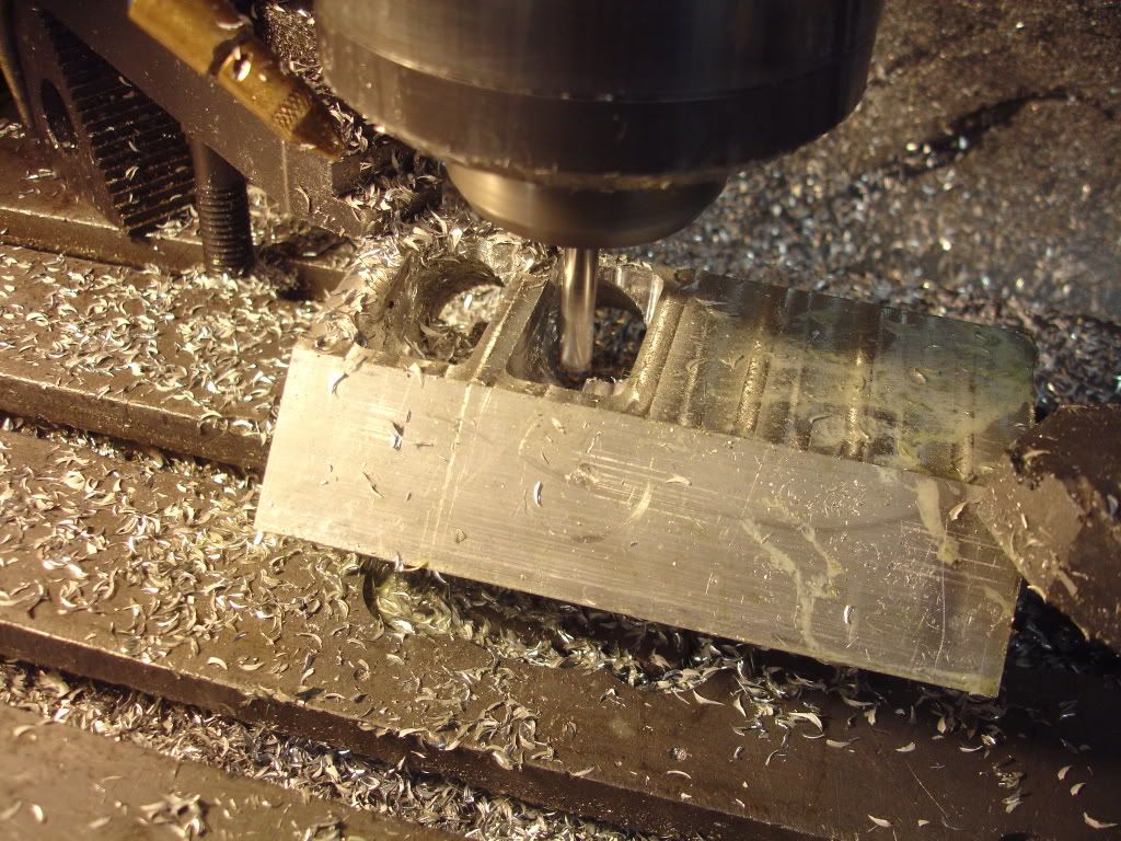
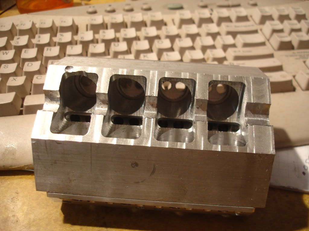
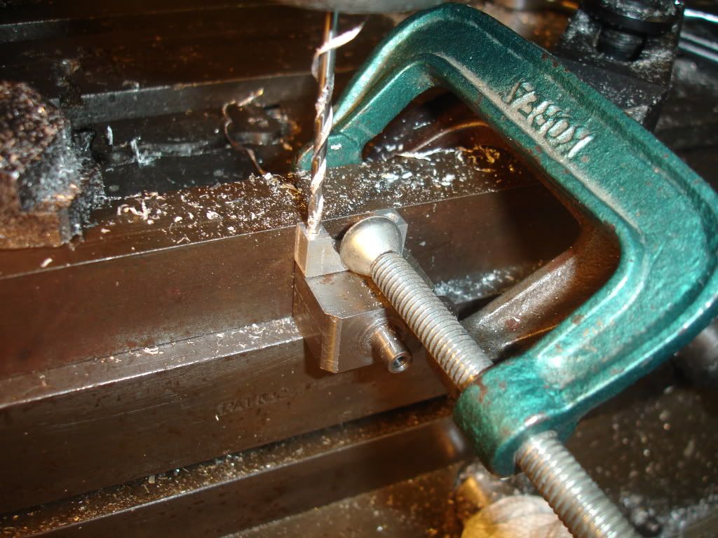
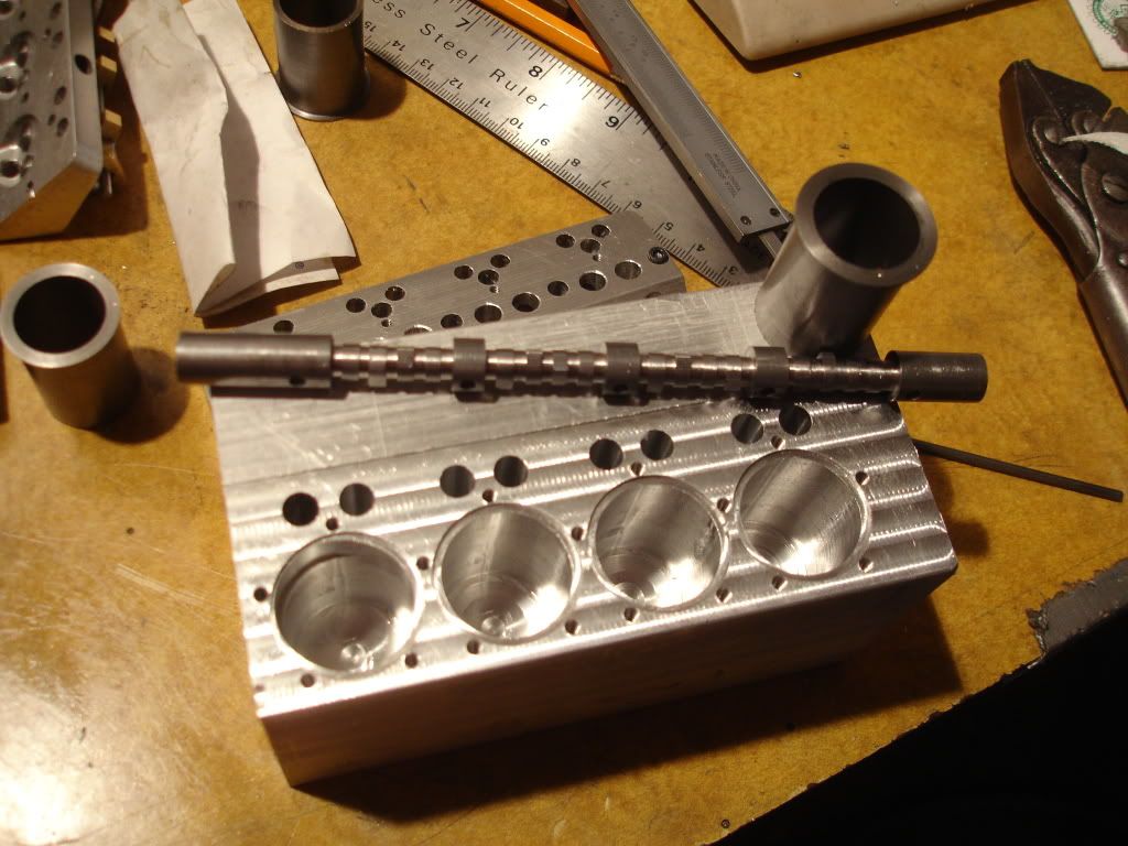
Because so many features are relaed to the cam position I decided to next drill the cam tunnel. Drilling a hole that deep has always been a challenge for me. I posted a querry on the forum about how to drill a deep hole straight and true. I got a lot of guesses but not much qualified real help. I googled the question and found whats referred to as a d-bit. Apparently it's the original gun drill. They're easy to make so I made one, drilled a test hole and was shocked at the results. I drilled a test hole in a 5 inch block with my homemade d-bit and got a hole that was accurate, straight and exited where it was supposed to. Try it, you'll like it. Just google d bit.

I know this one is a little smaller than the victory. How long is the block on this one?
 
4-3/4 long. I missed you at the meeting. Heard you have the croup. Get well soon.
 
Next job was to lay the block on its side and drill a million holes, tappet, cylinder and head bolt holes.
DSC02192.jpg

Notice I finished the deck. Turns out the block of aluminum isn't exactly 2.5 inches square and the sides aren't real flat either so I took care of that problem.
 
jpeter said:
4-3/4 long. I missed you at the meeting. Heard you have the croup. Get well soon.

Didn't get out of the doctors office until 7:30-8:00 so I would have been late. Didn't wan't to pass it along so i just stayed home. Helping a friend today so hoping for some garage time tomorrow.
 
Making Progress.
Notice I've got a little mess up on #1 cylinder. I doubt it'll hurt anything.
DSC02194.jpg
 
I had the misfortune of breaking off a tap in one of the head bolt holes. I did this on the last engine block too and at that time after the initial shock, heart attack, had to find a way to extract it. Looking for a way I ran across the homebuilt EDM at this web site, http://pico-systems.com/edm.html. I built the system from electronic stuff I had in the junk box and burned out the tap in short time. I made a tool from brass rod, insulated it with tape and chucked it in my CNC mill. I used the CNC control to plunge the burner through the broken 4-40 tap.

So I resurrected the electronics, made a brass stylus, and went to burning. I've tried different fluids for edm fluid and found for this small project WD-40 works very well. I built a coffer around the hole to contain the fluid with modeling clay. Then I powered up the system. I set the machine such that a dead short drew 4 amps on the meter (around 30 volts) then tried to maintain the feed rate so the current hovered around 2 amps. An occasional blast of wd-40 kept the current flowing at the proper rate. I set the downfeed at 0.06 inches/minute but from time to time had to lift the tool to break a short. I burned out the broken tap in about 10 minutes. The threads were still good.
 
stevehuckss396 said:
OH Buddy!!

You should have never told me you have an EDM!!!
ROAD TRIP!!! ;D
Just joking. I have been in search of some alum to try the chemical tap removal process myself. Due to the scarcity of chain grocery stores in SE Michigan and it not being canning season, I have not had much luck so far. I picked up a spiral 2 flute tap and dont expect to ever break that one, well worth the $13 from McMaster.
 
Building one is not to hard. Attached is a picture of mine setting in its storage place. Most any analog amp meter that goes to 5 amps will work. The big 50 watt resister could be replaced with automotive light bulbs. I used a motor starting capacitor from an old motor I already had and I had the variac although any source of dc volts most likely would work. You maybe could use a DC welder. I used a bridge rectifier from Radio Shack because the Variac outputs AC.
DSC02221.jpg

Just for fun I burned a 1/8 inch hole in a file.
DSC02222.jpg

And, I used a single strand from stranded copper wire to burn a hole through the shank of a #50 drll. I lost the drill before I got pictures.
 
stevehuckss396 said:
Famous last words!
Indeed, but I was firmly knocking on wood when I typed that P)

It is amazing as it lifts two long spirals of chip out of the hole. I tend to break all my 4-40 taps via clogging. I get greedy and try to finish the bottom of the hole without backing out that last time, and when I am removing the tap it breaks. Strictly bad practice on my part.

jpeter said:
Building one is not to hard. Attached is a picture of mine setting in its storage place. Most any analog amp meter that goes to 5 amps will work. The big 50 watt resister could be replaced with automotive light bulbs. I used a motor starting capacitor from an old motor I already had and I had the variac although any source of dc volts most likely would work.
That looks very interesting. I think I have the circuitry plan in one of my strictly IC issues. Different mode of thought, however, one project at a time. :)
 
Well I got back to the block. Here's a picture of me CNCing a cylinder hole.
DSC02199.jpg

I just had to, I bolted the heads on just to see how it looked.
DSC02204.jpg
 
Have to make room for the crank so I turned it bottom side up and started milling the crankcase.
DSC02200.jpg

I made some progress. I used a .25 solid carbide cutter and surfaced all the inside surfaces. The first cavity starts 3/8 back from the front, the webs for the 3 center bearings are 1/4 wide, and the rear bearing width is yet to be determined so its wider than need be. If I can cut helical spiral cam gears I'll move the distributor forward and some to the right cuz there's more room on the right side. If I have to use bevel gears the distributor will have to be mounted furthur back to avoid the #8 exhaust valve.

While I had it clamped up I milled slots into the camshaft tunnel for oil and used a 1/2 inch ball end mill to mill the block for the main bearings.
DSC02202.jpg
 
I made 5 main bearing caps. I drilled for the bolt holes using this setup.
DSC02205.jpg


The caps are held in place with 4-40 cap screws. To keep the caps aligned I bushed each hole with 1/8 drill rod bushings. I countered the holes in the blocks the same as the holes in the caps. The bushings are held in the cap side with LockTite. These bushings are pretty thin and fragle.
DSC02207.jpg
 
Back
Top