James Coombes Mine Engine from barstock

Home Model Engine Machinist Forum

Help Support Home Model Engine Machinist Forum:

This site may earn a commission from merchant affiliate links, including eBay, Amazon, and others.
Hi Phil
Just picked up on this build, so i had to read it from the beginning.
Absolutely brilliant, loved reading it. Your doing a fantastic job, can't wait
to read more.

This really is a Goodin :bow:

Ken
 
Philjoe5 said:
Many thanks Bob. I think I got the idea for the fixture from someone on this forum though I can't exactly remember who it was. ???

Cheers,
Phil

P'raps it was this one Phil - that would be my mine.


I see you are maintaining the high standard on the build - great stuff!
 
Ed, Arnold, Ken Tel,
Thanks for the support and praise.

Tel, it could have been one of your builds that gave me the fixture idea because I followed most of them all the way through.

Thanks for the inspiration to you :bow: and all others :bow: who post their tips, WIP’s, photos and ideas here. You are making this a great learning place.

Cheers,
Phil
 
Since my last progress report I’ve been working on the valve gear. I started with the valve connecting rod. This is a two piece affair with a ring having a slot cut into it and an arm or rod that fits in the slot. The pieces are soldered together according to the plans.

I decided to make (yet another) change. By making the ring slightly larger in diameter and cutting the slot slightly deeper, I’d have enough “meat” on the arm to pin it to the ring with no need to solder. So that’s what I did. But then that changed the plan dimensions for trimming of the arm. Using my crude drawing program I made some calculations for cutting. I experimented with a piece of aluminum for cutting arcs and angles. Then I made the final product in brass.

The next part on my list is the eccentric. This starts out as a 1.50” round of steel. Rooting around for some stock I found I didn’t have this size in my alloy of choice, 1144. I did locate a fairly crusty looking iron round that was 1.58” in diameter, an odd size I thought. When I cut it I realized it was cast iron, probably Durabar.

I drilled/reamed the offset crankshaft hole to 5/8” using the 4 jaw chuck on the lathe. This time I remembered that an offset of 0.125” in the eccentric means opposing jaws on the 4 jaw need to be 0.250” apart. I still had to stop and think about what I was doing when I saw the end of that workpiece wobbling around. At first I was sure that once I touched the center drill to it my drill bit was going to be ripped out of the drill chuck. It was only when I drilled up to ½” that I could finally focus on the hole and confirm in my mind it was running concentric to the lathe spindle axis. After I drilled to 0.562”, I bored to 0.610”, then finally reamed to 0.625”. The connecting rod and eccentric are shown here:

valvelinkconrodandeccentric.jpg


A valve link block was made from a block of brass. Nothing tricky here. Just drill mounting holes, ream for the valve link rod, and trim off the excess with an end mill.

The valve links were completed without any problems. I used my trusty fixture for rounding the valve links. I made a new pin that had a 5/16” slot milled into the head to prevent the valve link from rotating during this operation. I made a third rocker arm from brass like the previous two except this one is a little beefier with a longer boss. This rocker arm ties to the valve connecting rod. I also made one link pin out of 5/32” drill rod to see how it would fit in the rocker arm. I need to make two more of these.

The valve link cross arm came from some 3/8” hex CRS stock. The ends were turned to 5/32” for a close fit through the ends of the valve links. They were drilled with 1/16” holes on the ends to hold cotter pins. Here’s a photo of the valve gear arranged temporarily in place. I’ll eventually put these parts in place permanently with some loctite.

valvetrain1.jpg


Next week I may not spend much time in the shop making chips. I want to connect up the valve gear and check it out for free movement. That will be the last mechanical to test. Once that passes muster it’s a matter of making the remaining fittings to finish the engine…some pins for the valve links and rocker arms, flywheel (spoked from a casting), steam chest cover, intake/exhaust pipes, and finials.

Cheers,
Phil


Those are great looking parts Phil.
I'm really looking forward to seeing the run.
It's a nice engine.
 
Thanks Zee. You may see it running for real at one of the Kinzers, PA shows, after early June, if all goes well.

Cheers,
Phil
 
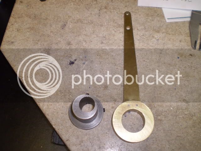
I made some valve link pins, and a third rocker arm which is driven by the valve connecting rod. Drilling 1/16” holes in the ends of 5/32” drill rod link pins required some care. Milling a flat with a 1/8” end mill, followed by a center drill before drilling resulted in no broken drill bits. :D

I had a piece of cast iron rectangle left over from the cylinder block stock. The plan dimensions called for stock 1/8” thick. I decided to make 1/8” boss to give me extra material to cut 1/4” – 28 NF threads for the inlet pipe. So I milled my stock to ¼” thickness. I center drilled it for a #10 screw, then mounted it on a fixture for turning the 1/8” thick boss on the lathe.

steamchestcoverlinkpin.jpg


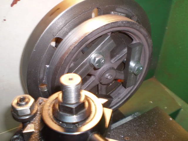
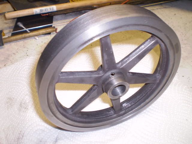
I machined a flywheel from a casting I bought at Martin’s Models at Cabin Fever. It’s 6” diameter and turned very nicely, no hard spots or voids…a treat to work with. I mounted the casting to the faceplate and machined the outer surface, the hub, the rim face, drilled/bored/reamed the center hole without removing the workpiece.

flywheelstart.jpg


With the outer surface true I mounted the flywheel in the 4 jaw and machined the other side. Then I drilled/tapped for two 10-32 set screws at a 30º angle in the hub boss. Finally I removed the flash using a Dremel tool with various sanding and grinding bits. I fastened the flywheel on some 5/8” drill rod in the lathe and spun it at 150 rpm and I could not detect any wobble.

Flywheelfini.jpg


Finials are made for attaching the table to the supports columns. I made them from 7/16” brass hex rod and some ¼” – 20 NC allthread. The brass hex was cut to length, threaded ¼” – 20 NC on one end. A 60º toolbit was used to cut two grooves and finally the end is tapered 30º. A piece of allthread wass cut to length, screwed into the brass hex rod and permanently attached using threadlocker. The result is a nifty Victorian era hex bolt. In this photo I haven’t yet removed the excess threadlocker.

finials.jpg


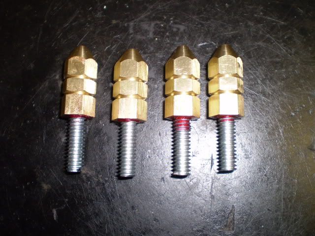
Finally I made some fittings for the intake and exhaust ports from some brass hex stock.
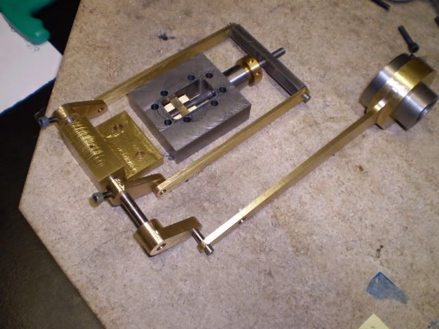
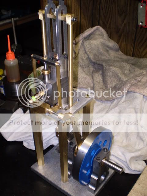
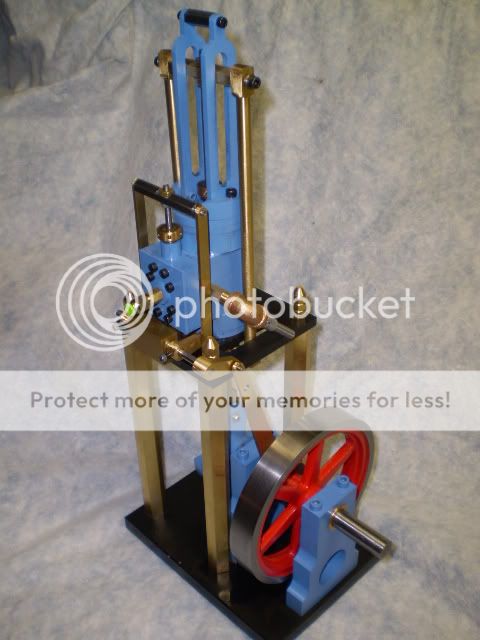
I’ve made all the parts to the engine. But an engine is more than the sum of its parts. I have the engine all put together with a temporary flywheel and standard hex head screws holding the table to the support columns. I decided to try a test run to make sure all my clearances and tolerances were going to cut the mustard.

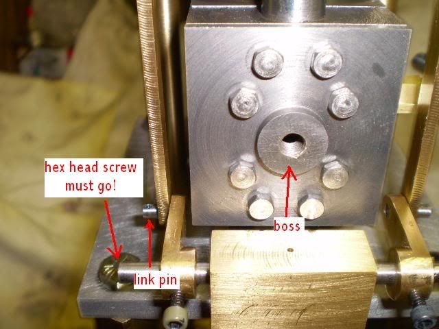
With the steam chest cover removed I started adjusting the timing to the engine with the valve linkage assembled. I’d never timed a sliding “D” valve engine like this before. The eccentric dimensions determine the travel length of the valve. The rocker arms on the link rod are used to adjust the position of the valve over the ports. With a few tries I had the engine running smoothly. This is the magical moment in every model engine builder’s life. All of a sudden, the reason for all those months of efforts are right there in front of you. I had a huge grin ;D ;D ;D ;D ;D planted on my face that took hours to wear off!

MineEnginerun1.jpg


[ame]http://www.youtube.com/watch?v=hx3ETDxRR_U[/ame]

Many thanks go to enginebuilder Tom for providing a great set of plans in a scale I can work with. All the dimensions were right on and the assemblies work nicely together. Also thanks go to all you HMEM members that took the time to look in and offer some encouragement, tips etc. – it is much appreciated. I have truly learned a lot by looking in on some of the works in progress here.

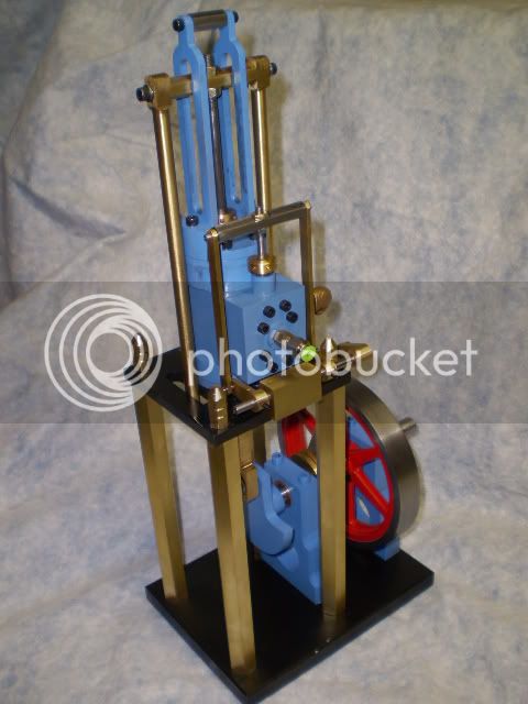
Now, all that remains is to strip this engine down, clean it, polish it up and paint some of the iron and steel and get it in show condition. I’ll post the final result as soon as its truly finished.

Cheers,
Phil


Really cool Phil.
Congratulations.
I was struck by the smoothness and sound.
 

Nice job Phil!

Congratulations.

 
Phil,

I am adding this engine to my build list.

This design has the classic, stately lines from the steam powered era.

Of course, it looks and sounds great.

Thanks for sharing.

SAM

 
Phil

Congratulations! You've done a wonderful job. ;D

My be we can put our engines side by side in York. It runs real nice.

Tom
 
Phil,

Great work. :bow:

Great runner. :bow:

Best Regards
Bob
 
Zee, Kevin, Sam, Tom, Bob, Rick,

Thanks for the cheers guys. It was a fun trip for me. There were some nice challenges in this build and I tried doing a lot of new things. That’s what it’s all about. Glad you all looked in from time to time and offered support and encouragement. Be sure to stop in one more time when I have her really finished.

Tom, see you at the next Cabin Fever in York, PA.


Cheers,
Phil
 
As promised I have photos and a video of the engine finished to my liking. I’ve been playing around with timing the engine and seemed to have gotten a smooth running engine. Here are two photos of the finished engine:

MineEnginefini.jpg


MineEng2c.jpg


Finally, a video, though at this stage I was still tweaking the timing

[ame]http://www.youtube.com/watch?v=0RTtqfSGhLw[/ame]

When I first began this engine there were a number of parts I wasn’t sure about making. But gradually, taking one step at a time, progress was made. It is unfortunate that I can’t personally thank all of those folks on this forum that gave me the solutions to making many of the components of this engine. But thanks to all of you for taking your time to post suggestions, or how-to’s, or pictures and videos of your work. Lots of ideas came from what I’ve seen on this forum. Add to that some experimentation plus good luck and voila = success!

I’m very pleased with how this engine runs. It has an interesting characteristic that I haven’t seen in my other horizontal or vertical engines. The connecting rod assembly is constructed of five brass parts and as such, has a fair amount of mass, much more than a normal connecting rod for an engine of this size. When I spin the flywheel from BDC, I have to give it quite the push to get it over TDC. Then of course, gravity takes over and pulls that mass (toward the center of the earth, I expect). I know I can counterbalance this mass, but I don’t believe the original engine did that. I wonder what kind of power curve this engine has compared to other designs? Did this make for a more suitable water pumping engine? Any thoughts on that?

As always thanks to all who stopped in and looked or chatted. :bow:

Cheers,
Phil

 
Looks (and sounds) great Phil.
I notice some tweaks..but also the flywheel. Why'd you change it?
Just wondering.
 
Phil,

Congratulations on another very fine engine. :bow: :bow:

Best Regards
Bob
 
Phil,

Your engine looks great. I like the color combination you chose. The engine has a nice sound to it. Keep up the good work.

SAM
 
Great runner and a fine build thread. Thanks for sharing Phil.
Gail in NM
 

Latest posts

Back
Top