James Coombes Mine Engine from barstock

Home Model Engine Machinist Forum

Help Support Home Model Engine Machinist Forum:

This site may earn a commission from merchant affiliate links, including eBay, Amazon, and others.

Philjoe5

Well-Known Member
Joined
Jul 12, 2007
Messages
1,727
Reaction score
321
I saw a model of the James Coombes Mine Engine at a show in Kent, Connecticut in 2006 and the exhibitor, Tom Kokinchak, was selling his plans for it. I was really impressed with the valve mechanism for the engine and bought the plans. At that time I was really a novice and closer inspection of the plans discouraged me from just jumping in to start it. For example, at the time I owned a lathe but did not have a four jaw chuck :shrug:. Well after 4 years, and many, many pounds of chips I‘m ready to tackle this project.

I thought I’d do this as a work in progress and post pictures of the various assemblies as they are completed. As usual, your comments and suggestions always welcomed.

First some background. I have, so far, not located a lot of information about the James Coombes Mine Engine. There’s some information on the Stuart website as they offer this engine as a castings kit. However, I’m still trying to find out who James Coombes was, how many of these engines were built and what, if any, advantage this design presented when compared to existing configurations. Anyone with info is welcomed to chime in here.
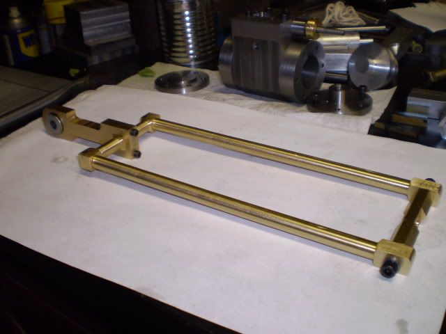
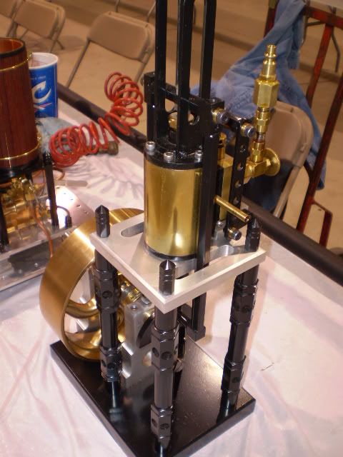
The engine I’m building is a barstock model. I recently saw a completed version at Cabin Fever last month. It was built by Steve from Massachusetts. Steve if you’re reading this, take a bow :bow:, because you made a very impressive looking model.

It is pictured here:
TKCoombes.jpg


There’s also a video of this engine here:
[ame]http://www.youtube.com/watch?v=ZCfXcAZTrO0[/ame]

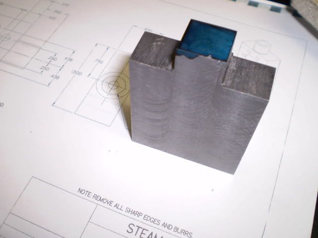
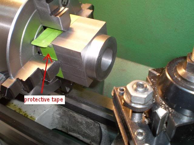
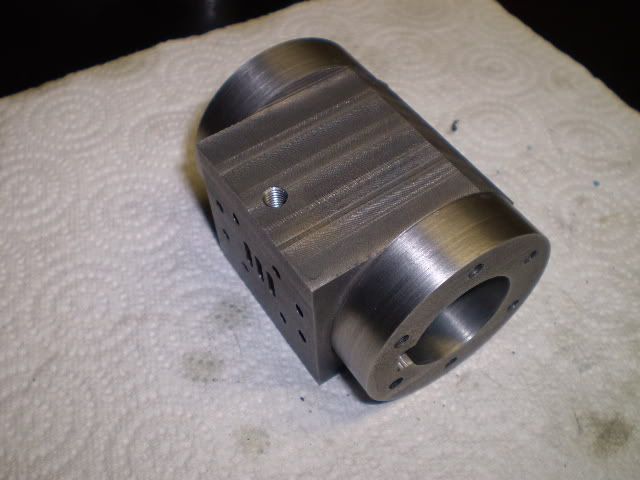
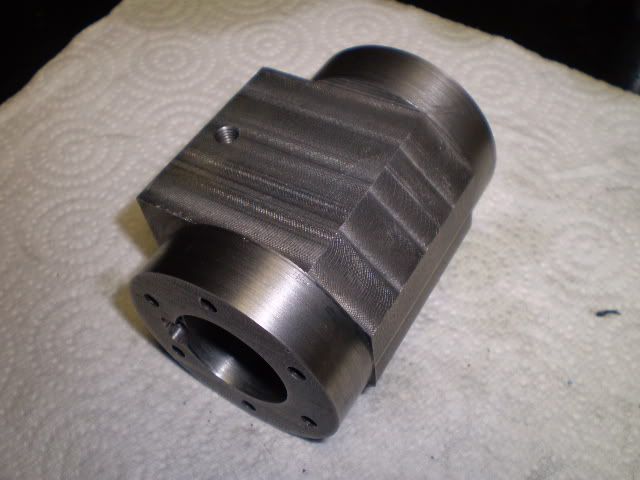
I started with the cylinder block. I had a lump of cast iron (Durabar) left from a previous project and began by milling a block to the overall dimensions.

I drilled and bored the cylinder on the lathe and then turned the ends to round them.

turningcylblock.jpg


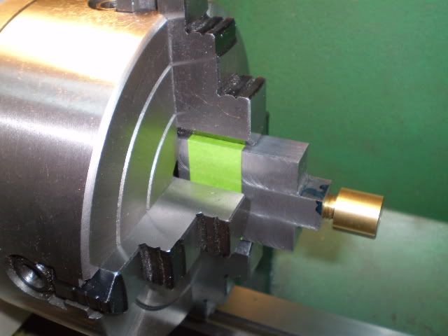
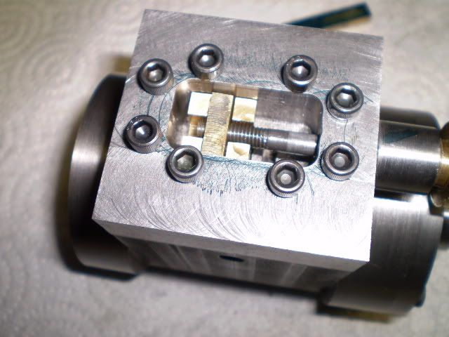
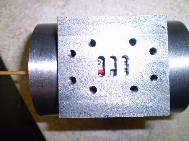
The steam chest mounting holes were drilled/tapped, the steam ports milled and drilled and the cylinder head mounting holes were drilled/tapped. When I angle drilled the first of four holes that connect the cylinder bore to the steam chest I had calculated the depth of the hole for the breakthrough of the drill. I always hold my breath when drilling the first one, because if any of my calculations or settings are wrong this is a great opportunity to make a paperweight. But all went well and the picture here shows a red tipped wooden dowel in the port on one end of the cylinder extending to the steam chest port (whew!) :)

angledrillingsuccess.jpg


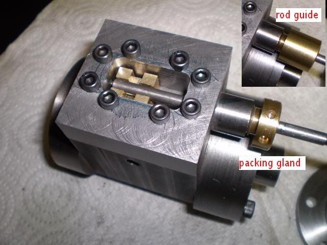
Some of the excess material from the central exterior of the cylinder block was milled away. Then the exhaust port was drilled and tapped. This completes the machining of the cylinder block.

cylbokvw2.jpg


cylblokvw1.jpg


This is all I have to report on for this session.

Cheers,
Phil

 
Good start Phil, I've always been attracted to the James Coombes as well, but, like you, haven't been able to find out much about it.
 
Hi Phil, very nice work on the cylinder. Although cast iron is somewhat dirty I really enjoy working with Durabar. It cuts really nice and clean and leaves nice sharp edges.
gbritnell
 
A very good start, Phil.
I'm another fan of this engine type. Glad to see a build here.

Dean
 
Tel, George and Dean,
Thanks for the encouragement. I am a big fan of Durabar, having discovered an outlet nearby makes it convenient. It does machine nicely, and except for looking like a coal miner after working with it for a day it does make great engine cylinders among other things. I did learn that it likes to be cut slowly, then alls well.

Cheers,
Phil
 
Hi Phil! The cylinder looks great! :bow:

I find your project engine interesting and a very good choice. I have used cast Dura-Bar for a cylinder along with a brass piston and find it to be a really good low friction combination. An aluminum piston should work equally well too.

I intend on building Elmer's #29 'Mine Engine' in the near future. Have you seen these plans, and are they the same basic design as the project your working on?

Plan links:

http://www.john-tom.com/ElmersEngines/29_mineEngine.pdf

http://groups.yahoo.com/group/Elmers_Engines_2/files/

Thanks.

-MB
 
MB,
Thanks for the complement. Yes, the Elmer's Mine engine looks like the same engine, though, on a smaller scale. I like the small scale engines, but the old peepers and fingers have difficulty with the small stuff.

I did finish an engine last fall using a Durabar CI cylinder with aluminum bronze piston and it ran very well on steam as well as air.

Good luck on your Elmer's mine engine. Keep us in the loop.

Cheers,
Phil
 
Thank you kellswaterri for sharing this article. :bow: That's some great background information on this engine

Cheers,
Phil
 
Philjoe5 said:
MB,
I like the small scale engines, but the old peepers and fingers have difficulty with the small stuff.

Good luck on your Elmer's mine engine. Keep us in the loop.

Cheers,
Phil

I know what you mean. I'm struggling with my current project. My eye sight has declined noticeably since November. And new pair of tri-focals would be very expensive. One or two more of "Elmer's scale" and I'm done. I'll have to find other projects, or upscale the remaining models available from Elmer's collection. I started using tweezers, and that's helped with the handling part of the small scale problem.

-MB

 
I used a piece of CRS I had on hand to make the steam chest. I milled away most of the excess material before turning the journal on the lathe.

steamcheststart.jpg


I also tapped the workpiece for the packing gland using a 7/16” – 20 NF tap.

When I tap a blind hole like this I usually start with a plug tap and then run a bottom tap in to get a few more threads. This is not a thread size I use often. I started rooting around in my tap stock and finally found a plug tap of this size, but no bottom tap. So this got me to thinking about where I used this particular tap in the past.

After searching some old records I found this is the thread I used for making a displacer rod guide for a Stirling engine. The rod guide screwed into the baseplate in a through hole, hence, no bottom tap needed. This engine never did run so I decided to scavenge the rod guide and make it a packing gland. I screwed this “rod guide” into the steam chest blank and used it as a reference surface to help true the workpiece in the 4 jaw chuck. I made the final adjustments to the four jaws by indicating off of the opposite faces on the workpiece.

turningsteamchest.jpg


Next, I located and drilled the 8 mounting holes for the steam chest. I chain drilled out the middle of the chest and cleaned up the interior with some side milling with a 1/4" end mill.

I decided that with a little machining the “rod guide” could become a “packing gland”. This photo shows the rod guide in the steam chest (inset) and its new function as a packing gland.

packinggland1fini-1.jpg


One of my better recycles.

At one time I was not really happy about making interrupted cuts on the lathe. But I found that if I use slow rpm’s (usually 150 but never more than 300) and slow feed rates I get good results and don’t end up chipping my toolbits.

I made the valve rod and cross nut which completes the steam valve assembly The valve movement seems pretty smooth so I don’t think further finishing will be needed at this point.

steamvalveassemblyfini-1.jpg


The next assembly I’m going to tackle will be the connecting rod. This actually consists of a number of arms, crossbars, the crosshead, and the crank journal. I’m going to take some artistic license in designing this but I’ll stick to the critical dimensions, of course.

Cheers,
Phil
 
OK Ed. Let's hope the journey ends at my planned destination, eh ;)

Cheers,
Phil
 
This post describes making the connecting rod assembly. I’ll start at the end with a picture of the completed assembly parts with their labels. If someone has other names for these parts I’d be happy to learn them.

conrodpartslabel-1.jpg


I’m following the plans for critical dimensions of this assembly but I’m designing the elements to make use of my available stock. The plans call for 5/16” hex brass for the arms which I did not have. I did have several feet of ½” square brass so I decided to use that. I’ve not had much practice in turning long lengths like this on the lathe and didn’t want to experiment with brass. So I built a prototype first using aluminum for the arms to try out my technique

prototype.jpg


The overall length of the arms is greater than 9 inches. The ends of the bars are 0.450” square, so I decided to mill the bars to that dimension, then turn them on the lathe to a diameter of 0.375”. Milling a 9” long bar in a 4” mill vise is a trick. The ends seems to vibrate much like having too much overhang in the lathe chuck, so I moved the workpiece such that the ends were central in the vise to get those dimensions reasonably close. Then I turned the bar between centers never having much more than 2” from the chuck face to turn at a time.

turningconrodarmtoround.jpg


To speed up the process of centering a 0.450” square bar in the 4 jaw chuck I made a jig. I knew I would be turning a number of 0.450” square workpieces on the lathe. So using a little trig (Thank you Mr. Werner) I calculated that a cylinder with a bore of 0.636” would just slip over a 0.450” square bar. Then I just slipped the collar over the bar and indicated off the collar. I don’t know if this is a common technique but I found it to be helpful.

indicatingfromcollar.jpg


I turned the length of the bar to a diameter of 0.375” and left the crosshead end square. The other end of the arm was turned down (male) to 0.250” to form a joint with the end of the crossarm which was reamed (female) 0.250”.

arm_crossarm.jpg


The joint where the crossarm meets the arm will eventually get a treatment of loctite and then I’ll pin them with some 3/32” drill rod. I’ll wait until engine assembly before making any of these joints permanent.

The crossarm also started out as a ½” square bar of brass. Each end was reamed ¼” to form a joint with the arm, and a portion of each end was turned down to 0.375”.

The connection from the crossarm to the journal was made starting with a 3/8” x 1” x 2” piece of brass. The journal end was drilled and bored to a diameter of 0.625”. I rounded the end on the rotary table, and cut out some of the excess metal in the middle. A sleeve made from CRS was made by turning a ¾” diameter rod to 0.625” to fit in the journal end. It was drilled 5/16” to fit a machine screw that will attach it to the crank web. The other end of the journal was milled to a square of 0.450”, drilled and tapped for two 6-32 machine screws. Then a cap made from a piece of brass and drilled for #6 screw clearance holes. This arrangement allows the journal to lock onto the crossarm.

journal_crossarm.jpg


I rounded the tops of the arms using a rotary table and a ¼” end mill. I made an aluminum fixture with a slight depression milled into it to prevent the workpiece from twisting free.

roundingarm.jpg


The crosshead was made from brass 7/16” hex rod. It was tapped on each end with 10-32 threads. The middle section was milled flat and finally drilled for a clearance hole to accept the piston rod.

Two sleeves that fit in the end of the con rod arms were made from 3/8” CRS. They drilled 3/16” for a #10 screw and turned to a diameter of 0.249” to fit in the arms. They have a 0.030” flange against which a #10 screw can be tightened.

All of the parts now have been made for this assembly.

The assembled con rod is quite rigid even without locking the joints, so I’ll probably give the engine a brief test run before making some of these joints a bit more secure.

conrodassembly.jpg


This completes another assembly for this engine. I’m not sure where I’m going next but I’ll decide soon. With all this snow outside this is prime shop time. Thanks for looking in.

Cheers,
Phil
 
It's really coming along well, Phil. Everything you've made looks just great.
You picked a great design for your build!

Dean
 
Jim, the lathe is a 10 x 22 Grizzly, Chinese made, a joy to work with. After 3 years of use I can’t find anything to fault it with except the fact that at times it allows an unskilled operator to work the controls ;)! Thanks for your support.

Dean, thanks for the encouraging words. Your support is appreciated.

Doing a work in progress is great fun, adding yet another dimension to this hobby. It makes me think twice (or more) about what I’m doing because I know I may need to explain what I was thinking at the time. It also forces me to stop along the way and take some photos which are of benefit to me down the road, plus it’s fun to view them after the fact.

So kudos to Rick and all the moderators :bow: for setting this forum up and giving us all these enjoyable aspects to model engine building.

Cheers,
Phil
 
Hi Phil, great work on the engine thus far. I really like the captioning of all the pieces in the photos. You used the packing gland for the valve rod guide which will work if your threads are very accurate. Tapping and die work doesn't always come out dead square and then it puts a little bit of a bind on the rod. I have done it that way in the past sometimes with luck and sometimes not.
gbritnell
 
George,
Thanks for the support and kind comments. Your point about tap and die threads is a good one. After I finished turning the “rod guide” into the packing gland I installed it in the steam chest. I’m getting smooth movement of the valve rod through its full stroke so this worked out OK.

Using a tailstock dieholder and tapping right after drilling the pilot hole produces good results for the work I’m doing which isn’t as demanding as some, that’s for sure. I posted a thread some time ago on this forum asking for help since I often got poor results with this approach. As usual I received very good suggestions that improved my success rate.

I should also mention that I practiced for a year before I could successfully make male/female threads this way most of the time.

Cheers,
Phil
 
Phil,
I'm really enjoying this build. Your engine is really looking good so far.
Dennis
 

Latest posts

Back
Top