James Coombes Mine Engine from barstock

Home Model Engine Machinist Forum

Help Support Home Model Engine Machinist Forum:

This site may earn a commission from merchant affiliate links, including eBay, Amazon, and others.
Your coming along really well Phil! super workmanship, and first class posting!
I really enjoyed seeing and reading you post. :bow:

Quote from Phil's post:
"I learned some time ago that you can skip the deburring steps in between. You are rewarded for doing this with some fine paperweights."

:big: :big: :big: :big: :big: (can!) Good one, I can't stop laughing!

-MB
 
Phil

Your doing great! :bow:

I know in my plans that the bearing block and cap are on different prints and are to the final dimensions. I also mounted unfinished bearing caps to the block before I made my final cuts. I was told many years ago as a draftsman to give final dimension and don't tell the tool maker how to do it.

If you have any questions on the plans or suggestions, just let me know.

Tom
 
You sure are doing up a nice job here, Phil. The bearing blocks look just dandy.
Great job!

Dean
 
Dennis, MB, Zee, Tom, Dean,
Thanks for the comments, encouragement, and kind words. Support from you guys is a great help in my making progress.

Zee – the crankshaft is slightly “out-of-spec” from another engine project and just happened to be the right diameter to go through these bushings. It’s too short to use for this engine but I used it to check bearing block alignment. It is painted “Oregano” (honest!) :eek:

Tom – I am recognizing the fact that engine plans usually do not contain details about how to go about making a part. I actually appreciate that since it adds a little more challenge to the build. A few years back I would have attempted to make those bearing blocks and caps as two separate pieces and then tried fitting them together…I probably would never have gotten them right. Your plans, BTW, have been great to work from :bow: – so far all dimensions are right on and the 3D perspectives of parts and assemblies is a great help to me.


Cheers,
Phil
 
Hi Phil, excellent work on your engine so far. The extra work on the bearing blocks rewards you with parts that have a nice character to them. It really adds to the overall look of the engine.
gbritnell
 
Good stuff Phil :bow: :bow:

Best Regards
Bob
 
Yeah Phil, you surely are making a nice job of it. I've nearly got to bump one of these up my list a bit!
 
George, Bob, Tel,
Thanks for stopping in and offering words of encouragement. I must say carving out those bearing blocks gave me an appreciation for why there are castings.

Cheers,
Phil
 
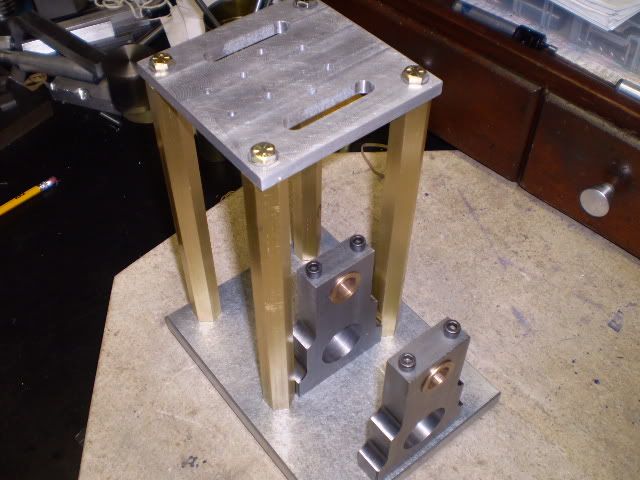
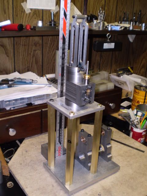
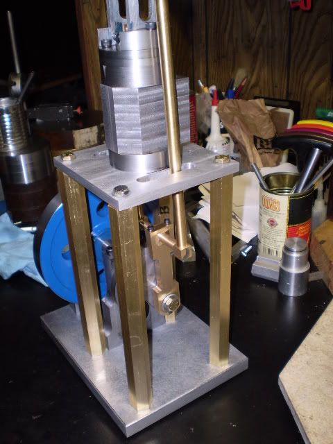
I made four support columns for the table using some ¾” hex brass. The ends have a 0.020” register on both ends that fit in recesses in the table and base. Both ends of the columns are tapped ¼” – 20 for mounting hardware. Note the hex head screws will eventually be replaced with finials made from hex brass stock.

supportcolumnsonbase.jpg


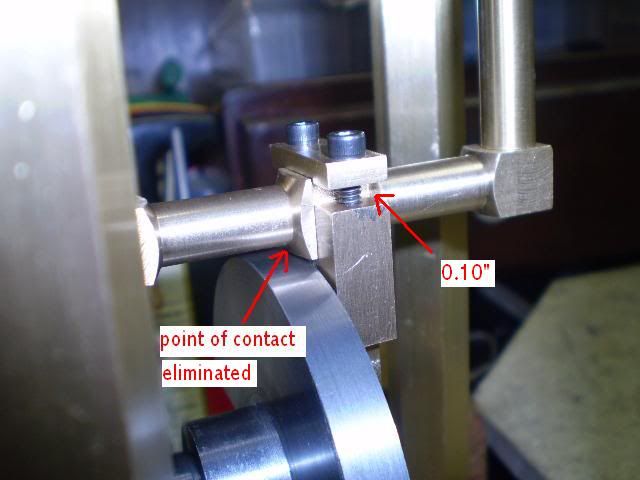
When I assembled the table to the base using the columns I made a trial fit of the con rod assembly through the table slots. I could have done this sooner, but I discovered that the arms of the con rod assembly were too close together and were wedged up against the slots in the table. This was not a design error. If I had followed the plans for the con rod arms, I would have had clearance.
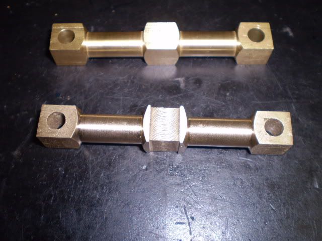
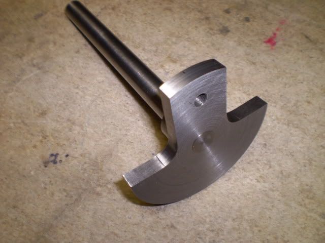
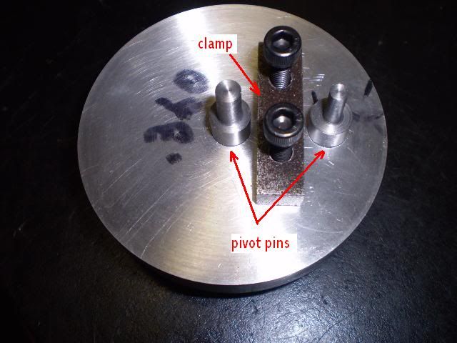
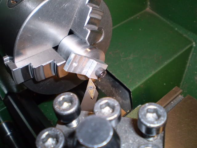
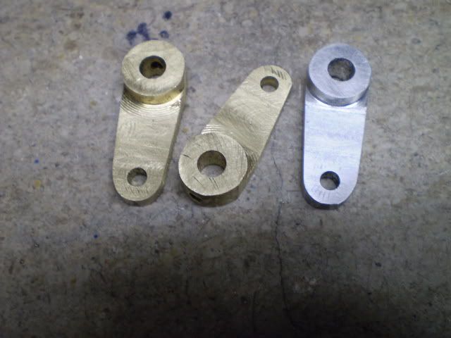
Now decision time – widen the table slots by about 0.025” or make a new con rod crossarm. I decided to make a new crossarm. First of all, I wanted to make a recess in the center of it to fit the journal. That would prevent any lateral movement of the journal.

Secondly, later on I’m going to pin these joints with taper pins. I’ve never used taper reamers so I can use the old crossarm to practice.

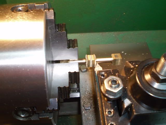
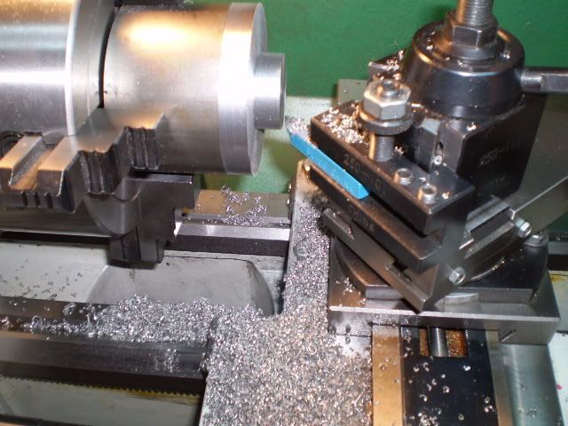
The only complication with making the recess on the crossarm was gripping the workpiece to turn down the second side of the arm. I had to grip the workpiece on the 0.450” square end which is only ½” long and that leaves me with quite a bit of overhang. My other option would have been to make a split ring and grip the round part of the arm in a 3 jaw chuck. I decided to risk the overhang and take light cuts and that worked out OK.

overhang.jpg


newandoldxarm.jpg


I made a packing gland from some ¾” bronze. Turned the required length of the gland to a diameter of 0.730”. Then turned a length of 0.613” to a diameter of 0.494”. Using the tailstock dieholder I turned ½” – 20 NF threads on the workpiece. Except, my diameter was too high (0.495”) and I couldn’t cut to the shoulder. Plus the threads got buggered which has been my experience when I try to cut them on a diameter that’s too high.

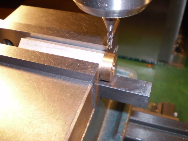
I made a second gland by turning the threaded part down to 0.484” and had no trouble. I drilled a clearance hole in the workpiece with an “F” (0.257”) drill. Parted off the workpiece. I had a piece of ¾” aluminum hex bar that had been drilled/tapped ½” – 20 from making packing glands for other engines. I screwed the packing gland into the fixture and faced the gland to its required length. Then I drilled six holes using a 1/8” end mill. The hex fixture makes this a simple procedure.

drillinggland.jpg


With the gland held in the three jaw chuck of the lathe and the upper cylinder head screwed on, the TIR on the rim of the cylinder head was 0.015”. Not very good, but I expected as much at this point.

Both ends of the gland had been faced off before any of the other machining operations. But under magnification its apparent that thread cutting produced a significant burr on that end of the workpiece. This end butts up against the bottom of the threaded hole in the cylinder head. So off to my surface plate with some #500 grit paper to polish the threaded end, and wire brush the threads. Then a thorough cleaning of the bottom of the threaded hole in the head. Reassemble, and measure TIR on the rim – 0.004”. That seems acceptable from my past experience with an engine of these dimensions.

The piston rod was made from a piece of ¼” drill rod. Each end was to be threaded ¼” – 28 NF. I turned the diameter down to 0.240” on both ends for the section to be threaded. Then, using a tailstock dieholder I made, threads were cut to a length of 0.625” on the piston end and 1.250” on the crosshead end.

I used a piece of aluminum bronze to make the piston. After facing, I turned the diameter to 1.250”. The cylinder bore is 1.200” and the piston will be turned to fit the bore once it’s installed on the piston rod. I drilled it with a #3 drill for ¼” – 28 NF threads. Then I faced the other end for an OAL of 0.625”. Threads were cut by using a diestock held up against the face of the drill chuck in the tailstock. Once started this way, the threads were cut through the piston blank.

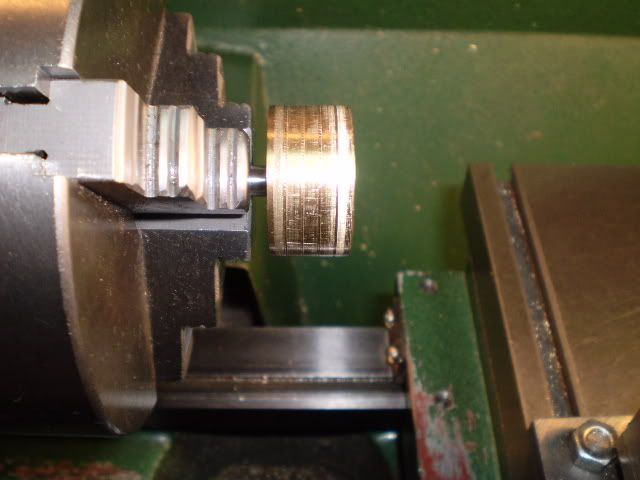
The piston rod was held in the 3 jaw chuck on the lathe and the piston screwed on tightly. I measured TIR of 0.003” on the piston. This measurement tells me that cutting the threads on the piston rod and piston went reasonably well. Once the piston was turned to its final size, TIR was about 0.000”.

I had an aluminum dowel of diameter 1.201” which I thought was a fairly good fit in the bore. I decided to turn the piston to 1.202” for a trial fit. I managed to nearly hit that diameter but the piston wouldn’t clear the bore. I gave it a few light polishes with some #500 sandpaper until it could fully enter both ends of the cylinder. Then I cut 4 oil grooves 0.004” deep using an E4 toolbit. A final deburring, and the piston seems a good fit in the cylinder, not too loose, not too tight.

pistonfini.jpg


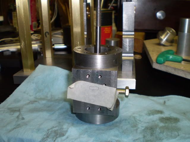
To test the fit I placed a piece of tape across the steam ports, and closed off the exhaust port and put the cylinder on a piece of oiled paper. If the piston crashed to the bottom it’s too loose, then I’d have to start over. If it didn’t descend it would need a bit of polish. The piston very slowly descended under its own weight so I think I have a winner. Though I can explain what I did in a few sentences it took me a number of hours to finish the piston to my satisfaction. Lots of light cuts and deburring near the end.

pistontest.jpg


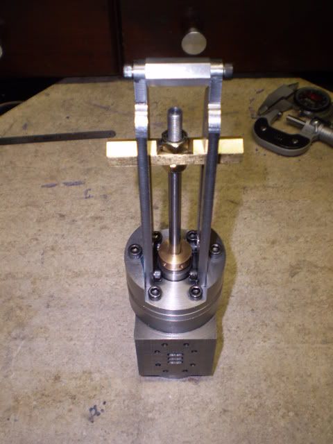
At this point I have all the parts needed to test the function of 3 assemblies I’ve made. I took the cylinder and attached the upper head, crosshead base and rails. I poked the piston rod with piston attached through the upper head and attached it to the crosshead.

pistonxheadassembly.jpg


Movement of the crosshead is slightly tight but it’s what I would call “ready to be worked in”. So, I’m ready to make the crankshaft and test the fit of the con rod assembly.

This is going to be a tall engine – 18+ inches. :eek:

tallengine1.jpg


Cheers,
Phil
 
That's looking great Phil.
I liked the tip on fitting the piston. That's an area I need to especially work on.
 
Hi Phil. Your project is coming along real well with excellent machine work.

I see what you mean. That is a large engine at 18 inches, and without a base under the platform. With 3/4" columns, a big cylinder, a large piston, and a 1/4" rod, just to mention a few items, will also make it pretty hefty engine too.

Keep up the good work!

-MB
 
Thanks Zee, MB. Zee, glad you found the tip helpful.

Cheers,
Phil
 
I spent this week working on the crankshaft. I wanted to test the function of the 5 assemblies: the base, cylinder, piston, crosshead, and crankshaft. When I began building model engines a few years back I would make each part without thinking too much about how it fit into the overall build. As a result I would make all the parts and then in a mad burst of energy I’d assemble them all and …..oops, this won’t rotate, or this part won’t fit into this part etc. etc. :wall: Then it was back to studying all the subassemblies to try to locate the source(s) of the problem(s). Now that I’m older and just slightly wiser, as I go along I try to test as much of the engine movement that I can. Now I usually have no big surprises at the end.

The crankshaft is a classic two piece design for a single cylinder engine. A shaft is press fit into a crank web. I went for a tight fit and will eventually make it permanent with a pin and/or loctite.

The web starts as a 3+ inch round of alloy (1144). A short length is turned down to form a hub. Lots of chips are produced.

lotsocutting.jpg


I drilled/reamed the web then sliced it off on the bandsaw. Holding the hub in the chuck, the major diameter was faced to length.

I clamped my 4” three jaw chuck to the mill/drill table and held the workpiece by the hub. I drilled/tapped threads for the crank journal. Then I drilled two 5/8” holes to form the radii for the web cutouts. A slitting saw was used to remove material up to the radii. Some light sanding with the Dremel sanding drum and the crank web is complete.

A piece of 5/8” drill rod was cut to a length of 7”, and the end turned down to fit to the crank web.

crankshaft.jpg


Since I have made modifications to the original plans for the connecting rod assembly I’m reluctant to permanently assemble these unless necessary. As it turns out this was a good plan because when the crankshaft was connected to the con rod assembly I was getting interference between the crank web and the crossarm of the con rod. By backing off on the screws of the cap of the con rod arm and lifting the crossarm I found I had about 1/8” of metal to “move out of the way”.

webcontact.jpg


Several fixes were available to me. I didn’t want to just mill away metal from a “good” part to accommodate a “bad” part so I chose to simply make a new con rod arm with an extra 1/8” between the crossarm notch and the journal.

newconrodarminstalled.jpg


Please ignore the garishly painted flywheel - it is temporary. I have no idea what I was thinking when I chose that color ???.

Full rotation of the crankshaft was now possible. Now I wanted to test the functions of the piston, crossarm and con rod assemblies. I belted the engine to one of my steam engines to check for smoothness of movement. Here’s a short video of this test.

[ame]http://www.youtube.com/watch?v=JhUwY-MuiaE[/ame]

Everything seemed to move OK :D, so I’m ready to begin working on the valve linkage.


Cheers,
Phil


Looks real good Phil! :bow:

The connecting rod mod Was a good way to do it. 8)

A steam engine, running a steam engine! simply brilliant! :bow: :eek:

-MB
 
I’ve made the rocker arms for the valve linkage mechanism. I spent a bit of time trying to decide how to sequence my operations. I picked some aluminum to test out my decisions instead of screwing up some expensive brass. Good thing too, because I made 3 prototypes before getting a reasonable part. Here is what I came up with.
• Mill some brass blanks to size
• Drill 3/16” (big end) and 5/32” (small end) holes
• Drill tap 6-32 threads on big end for a locking screw
• Mill most of the small end of the rocker to a thickness of 0.156”
• Mount the big end on a fixture using a #10 screw
• Turn the big end round to a depth of 0.156” on the lathe using a profiling toolbit
• Ream the big end 7/32” to specs and to fit one of the pivot pins
• Profile the remaining thickness of the big end using the rotab with 1/8” end mill
• Profile the small end and guesstimate how far around to mill
• Mill the 5º angle on each side on the mill/drill. Use a 5º angle plate for a guide

Here’s a picture of the fixture I used to round the ends of the arm.

rockerarmfix1note.jpg


Here I’m about to round half the depth of the big end. I tried cutting the full depth of the profile with a 1/8” end mill but was getting too much flex to get a good finish. I had to use a 1/8” end mill because of the clamping bar on the fixture.

latheprofilerocker.jpg


I have no idea if this is the easiest way to make this part, but with a bit of polishing they should function OK.

rockerarms.jpg


A lot of tool swapping when I was making these… drill, drill, tap, mill, turn on the lathe, ream, mill, mill but I liked the challenge.

Cheers,
Phil


Phil,

Neat fixture and I like the method. :bow: :bow:

Best Regards
Bob
 
Many thanks Bob. I think I got the idea for the fixture from someone on this forum though I can't exactly remember who it was. ???

Cheers,
Phil
 
That's coming along nicely Phil; good job!

Regards, Arnold
 

Latest posts

Back
Top