
You are using an out of date browser. It may not display this or other websites correctly.
You should upgrade or use an alternative browser.
You should upgrade or use an alternative browser.
James Coombes Mine Engine from barstock
- Thread starter Philjoe5
- Start date


Help Support Home Model Engine Machinist Forum:
This site may earn a commission from merchant affiliate
links, including eBay, Amazon, and others.
Philjoe5
Well-Known Member
- Joined
- Jul 12, 2007
- Messages
- 1,727
- Reaction score
- 321
I noticed in one of my posted pictures there are two cylinder heads in the background but I havent described how I made them so Ill do that in this post.
The plans specify brass for the lower and upper cylinder heads. This gives a great contrast to the cast iron cylinder when theyre installed. But I dont have any brass of 2.25 diameter in my stock and based upon the current price of more than $6/lb its unlikely Im going to acquire any soon. I decided to just make them out of steel, a 1144 alloy, AKA free machining steel. I get this from a local machine shop as drops and I really like working with it.
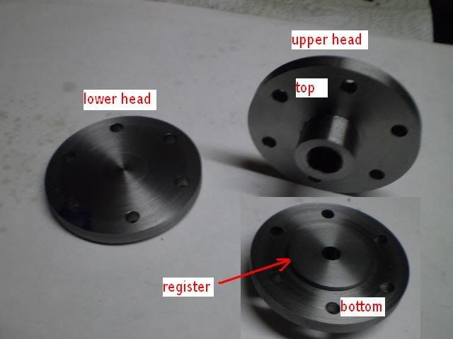
The cylinder heads look deceptively easy to make. And really the upper one is a matter of just taking the usual care in turning stock to the specified diameter of 2.238 and laying out the holes for mounting it to the cylinder. It has a hub on the topside which is threaded ½-20 NF. I did all the operations in a 3 jaw chuck without removing the workpiece, except for making the register on the bottom. I started the threads with the workpiece in the lathe chuck. Using a ½-20 plug tap in drill chuck in the tailstock I started the threads. They were finished afterward with a bottom tap. Then I switched the workpiece around holding the hub in the lathe chuck while I turned down the register on the bottom of the cylinder head. I like to make the register to within a few thousandths of fitting in the bore. With the workpiece still in the chuck, I moved it to the mill/drill table and drilled the six mounting holes.
The lower cylinder head is machined from the same piece of stock that had been turned down to 2.238. However, the cylinder head is only 0.240 thick which is a trick to hold properly in the lathe chuck for cutting the register and holding the workpiece for drilling the mounting holes. I did make a spider for my 4 three jaw lathe chuck (thanks again black85vette for that post). However this cylinder head is too large for that chuck. I could make a spider for my 5 three jaw, but I decided to try a shortcut.
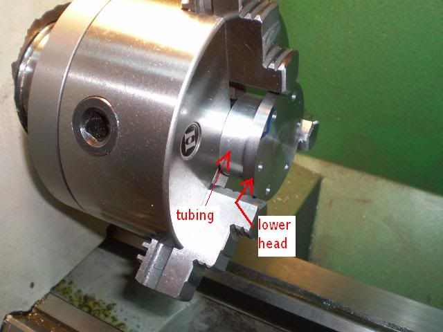
I made the lower cylinder head with a solid 3/8 hub on it. I used that hub to hold the workpiece for cutting the register and drilling the mounting holes. After those operations it needed to disappear.
I have some 2 diameter aluminum thick walled tubing. I cut a piece of that and faced off both sides. I set that against the chuck face. Then I set the cylinder head against the tubing. I measured TIR of 0.002 on the face of the cylinder head which I considered acceptable. Then with an AL5 toolbit @ 150 rpm I just faced off the hub until it was gone.
This photo shows the completed cylinder heads with the inset showing the register on the upper cylinder head
As I study the plans for the crosshead guide base I realize that it is just like the lower cylinder head in some respects. Had I looked ahead, I could have made this part along with these two cylinder heads in a more efficient process. But, since Im the boss, and I have no production deadlines to meet, so what?
Im going to tackle the crosshead guide assembly next. This assembly looks simple but its going to take me some time to get my head around some of the machining ??? that needs to be done. Expect a long pause here.
Cheers,
Phil
The plans specify brass for the lower and upper cylinder heads. This gives a great contrast to the cast iron cylinder when theyre installed. But I dont have any brass of 2.25 diameter in my stock and based upon the current price of more than $6/lb its unlikely Im going to acquire any soon. I decided to just make them out of steel, a 1144 alloy, AKA free machining steel. I get this from a local machine shop as drops and I really like working with it.
The cylinder heads look deceptively easy to make. And really the upper one is a matter of just taking the usual care in turning stock to the specified diameter of 2.238 and laying out the holes for mounting it to the cylinder. It has a hub on the topside which is threaded ½-20 NF. I did all the operations in a 3 jaw chuck without removing the workpiece, except for making the register on the bottom. I started the threads with the workpiece in the lathe chuck. Using a ½-20 plug tap in drill chuck in the tailstock I started the threads. They were finished afterward with a bottom tap. Then I switched the workpiece around holding the hub in the lathe chuck while I turned down the register on the bottom of the cylinder head. I like to make the register to within a few thousandths of fitting in the bore. With the workpiece still in the chuck, I moved it to the mill/drill table and drilled the six mounting holes.
The lower cylinder head is machined from the same piece of stock that had been turned down to 2.238. However, the cylinder head is only 0.240 thick which is a trick to hold properly in the lathe chuck for cutting the register and holding the workpiece for drilling the mounting holes. I did make a spider for my 4 three jaw lathe chuck (thanks again black85vette for that post). However this cylinder head is too large for that chuck. I could make a spider for my 5 three jaw, but I decided to try a shortcut.
I made the lower cylinder head with a solid 3/8 hub on it. I used that hub to hold the workpiece for cutting the register and drilling the mounting holes. After those operations it needed to disappear.
I have some 2 diameter aluminum thick walled tubing. I cut a piece of that and faced off both sides. I set that against the chuck face. Then I set the cylinder head against the tubing. I measured TIR of 0.002 on the face of the cylinder head which I considered acceptable. Then with an AL5 toolbit @ 150 rpm I just faced off the hub until it was gone.
This photo shows the completed cylinder heads with the inset showing the register on the upper cylinder head
As I study the plans for the crosshead guide base I realize that it is just like the lower cylinder head in some respects. Had I looked ahead, I could have made this part along with these two cylinder heads in a more efficient process. But, since Im the boss, and I have no production deadlines to meet, so what?
Im going to tackle the crosshead guide assembly next. This assembly looks simple but its going to take me some time to get my head around some of the machining ??? that needs to be done. Expect a long pause here.
Cheers,
Phil
Philjoe5
Well-Known Member
- Joined
- Jul 12, 2007
- Messages
- 1,727
- Reaction score
- 321
When I first studied the plans for this engine three assemblies seemed like they would be more of a challenge than the others
. the cylinder block, the crosshead guide assembly and the connecting rod assembly. This post will describe how I made the crosshead guide assembly.
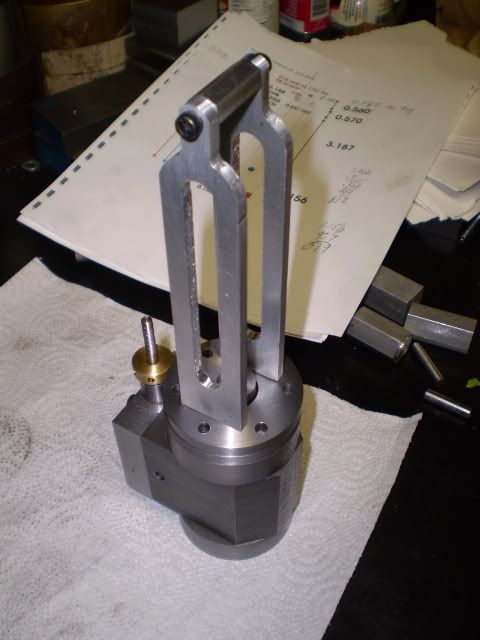
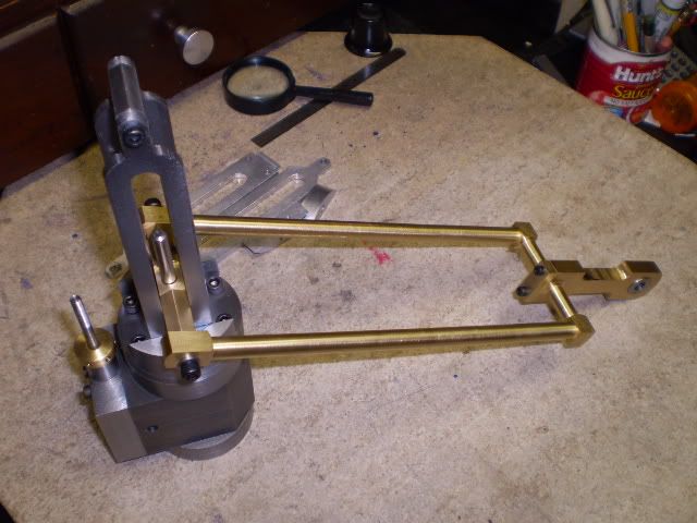
The crosshead assembly consists of a base, two identical guides and a crossarm. Heres a photo of the assembly with parts labeled.
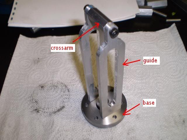
The guides were constructed first. The plans call for brass guides and crosshead. I didnt want to have brass running on brass so I made the guides from some CRS 1018 stock. I had some 7/16 brass hex stock for the crosshead.
The guides are radiused in two places with a slot for the crosshead movement. They are also notched on the bottom to fit into slots milled into the base. The guides started out as blanks that were milled to 3/16 x 1.062 x 5.500.
Using my basic computer drawing program (Corel Draw, version 3.0, 1992!) I calculated where to drill holes for the transition of the curves on the shoulder of the guide. Unfortunately, I wasnt careful in laying out my drawing and I drilled the holes for the shoulder of the guides a bit too low.
While I was cutting this radius on the rotary table it didnt look right but I plunged ahead thinking I could do a little creative filing to make it right. Not really.
Not having a lot of time or material invested at this point I decided to start over with two new guide blanks. But I decided to make the crosshead guide base next. In the past, when I screw up I tend to stop working on that part and pick up somewhere else. Then I spend some time thinking about how to avoid another mistake before making a second attempt.
The base for the crosshead is basically another cylinder head with two slots cut into it for the guides. The base is like another cylinder head and could have been made more efficiently when I made the cylinder heads and had the machines setup. I dont know whos doing my performance review this year but I think Im up the proverbial creek.
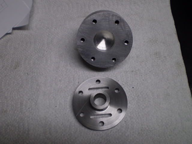
I decided to make a fixture for holding the workpiece for facing and boring operations. The fixture is a piece of aluminum with a 1.750 bolt circle to match the cylinder head mounting pattern. The fixture is shown here along with the base. At this point the base has a hub on it that I used to hold the workpiece for facing, and drilling operations. Now the hub needs to disappear.
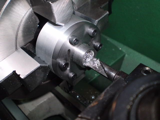
The following picture shows the boring operation to remove the hub and open up the center hole to a diameter of 13/16 to finish the base.
Now Im ready to make a new pair of guides. This time Ill use aluminum stock to make a prototype of the assembly. It machines much faster and its the cheapest material I have on hand to work with. I recalculated where my shoulder transition points occur and milled/drilled as needed. This picture shows the radius for the shoulder of the guide scribed on the workpiece. It appears that I did my homework this time.

After milling and drilling away material the guides were finished.
The crossarm was made from a piece of 3/8 hex bar thats tapped on the ends for #8 screws. The crosshead assembly sitting on the cylinder block is shown here.
At this point I have one more detail to take care of before completing the assembly. The plans call for silver soldering the guides to the base. This isnt an option for this aluminum prototype and I dont want to silver solder the final steel assembly, so Im taking an alternate approach.
Im going to make two brackets that follow the curve of the cylinder head. Theyll serve as anchors for the guide rails.
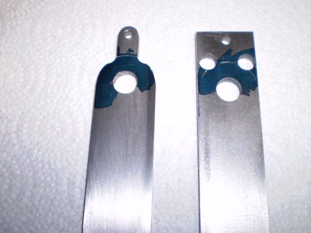
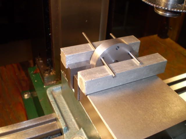
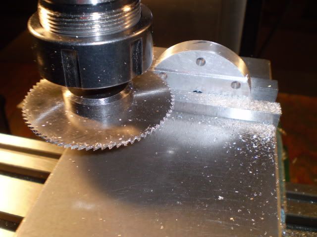
With a slitting saw I cut one of the brackets from a piece of stock that was turned to the same diameter as the cylinder head. It has 6 holes drilled on the 1.750 bolt circle, same as the cylinder heads. Using two of those holes as guides, I inserted two 1/8 rods that rested on top of square stock on top of the vise. Once clamped in the vise, Ive ensured that the bracket will align properly.
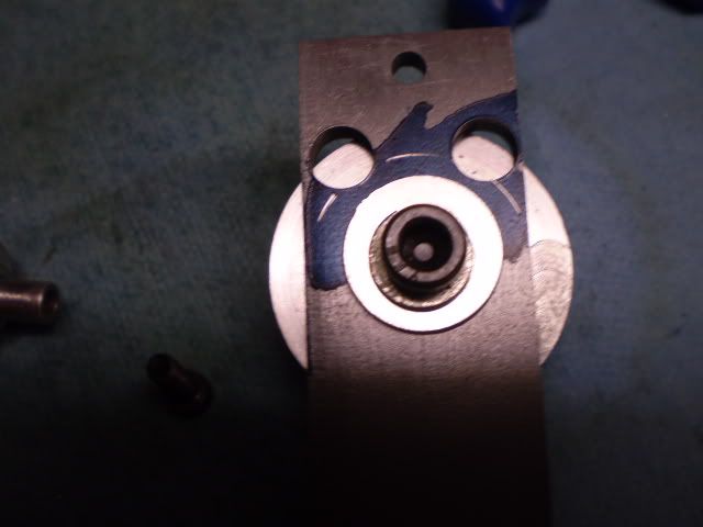
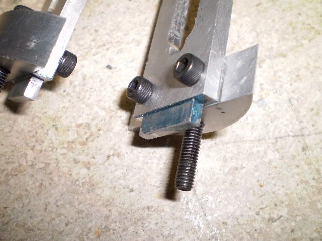
The bracket is tapped for 8-32 threads and the guides are drilled for #8 screws. Heres a closeup of the male part of the motise tenon joint for the guide and base.
Im satisfied with the aluminum guides and brackets I made. Alignment is good so I went ahead and made a set out of steel stock and, of course, second time around had fewer (though not zero) surprises.
Here are my 3 most challenging assemblies completed except for some polishing and painting
Now that theyve been made, Im breathing a little easier. I feel like Ive climbed a long steep hill. I expect more hills, though maybe not as steep, and eventually a nice coast downhill?
Of course, an engine is more than just the sum of its parts. All the parts have to work together. So now my focus will be to see if these assemblies will cut the mustard, Thm: or cut the cheese. :wall:
Cheers,
Phil
The crosshead assembly consists of a base, two identical guides and a crossarm. Heres a photo of the assembly with parts labeled.
The guides were constructed first. The plans call for brass guides and crosshead. I didnt want to have brass running on brass so I made the guides from some CRS 1018 stock. I had some 7/16 brass hex stock for the crosshead.
The guides are radiused in two places with a slot for the crosshead movement. They are also notched on the bottom to fit into slots milled into the base. The guides started out as blanks that were milled to 3/16 x 1.062 x 5.500.
Using my basic computer drawing program (Corel Draw, version 3.0, 1992!) I calculated where to drill holes for the transition of the curves on the shoulder of the guide. Unfortunately, I wasnt careful in laying out my drawing and I drilled the holes for the shoulder of the guides a bit too low.
While I was cutting this radius on the rotary table it didnt look right but I plunged ahead thinking I could do a little creative filing to make it right. Not really.
Not having a lot of time or material invested at this point I decided to start over with two new guide blanks. But I decided to make the crosshead guide base next. In the past, when I screw up I tend to stop working on that part and pick up somewhere else. Then I spend some time thinking about how to avoid another mistake before making a second attempt.
The base for the crosshead is basically another cylinder head with two slots cut into it for the guides. The base is like another cylinder head and could have been made more efficiently when I made the cylinder heads and had the machines setup. I dont know whos doing my performance review this year but I think Im up the proverbial creek.
I decided to make a fixture for holding the workpiece for facing and boring operations. The fixture is a piece of aluminum with a 1.750 bolt circle to match the cylinder head mounting pattern. The fixture is shown here along with the base. At this point the base has a hub on it that I used to hold the workpiece for facing, and drilling operations. Now the hub needs to disappear.
The following picture shows the boring operation to remove the hub and open up the center hole to a diameter of 13/16 to finish the base.
Now Im ready to make a new pair of guides. This time Ill use aluminum stock to make a prototype of the assembly. It machines much faster and its the cheapest material I have on hand to work with. I recalculated where my shoulder transition points occur and milled/drilled as needed. This picture shows the radius for the shoulder of the guide scribed on the workpiece. It appears that I did my homework this time.
After milling and drilling away material the guides were finished.
The crossarm was made from a piece of 3/8 hex bar thats tapped on the ends for #8 screws. The crosshead assembly sitting on the cylinder block is shown here.
At this point I have one more detail to take care of before completing the assembly. The plans call for silver soldering the guides to the base. This isnt an option for this aluminum prototype and I dont want to silver solder the final steel assembly, so Im taking an alternate approach.
Im going to make two brackets that follow the curve of the cylinder head. Theyll serve as anchors for the guide rails.
With a slitting saw I cut one of the brackets from a piece of stock that was turned to the same diameter as the cylinder head. It has 6 holes drilled on the 1.750 bolt circle, same as the cylinder heads. Using two of those holes as guides, I inserted two 1/8 rods that rested on top of square stock on top of the vise. Once clamped in the vise, Ive ensured that the bracket will align properly.
The bracket is tapped for 8-32 threads and the guides are drilled for #8 screws. Heres a closeup of the male part of the motise tenon joint for the guide and base.
Im satisfied with the aluminum guides and brackets I made. Alignment is good so I went ahead and made a set out of steel stock and, of course, second time around had fewer (though not zero) surprises.
Here are my 3 most challenging assemblies completed except for some polishing and painting
Now that theyve been made, Im breathing a little easier. I feel like Ive climbed a long steep hill. I expect more hills, though maybe not as steep, and eventually a nice coast downhill?
Of course, an engine is more than just the sum of its parts. All the parts have to work together. So now my focus will be to see if these assemblies will cut the mustard, Thm: or cut the cheese. :wall:
Cheers,
Phil
kellswaterri
Senior Member
- Joined
- Oct 14, 2007
- Messages
- 117
- Reaction score
- 6
Coming along nicely Phil, I like the use of ''non ferrus'' for the linkages...might just go for that myself.
All the best for now,
John.
All the best for now,
John.
zeeprogrammer
Well-Known Member
- Joined
- Mar 14, 2009
- Messages
- 3,362
- Reaction score
- 13
Nice Phil.
I like that style of engine.
And I'm enjoying your thread.
I like that style of engine.
And I'm enjoying your thread.
- Joined
- Dec 28, 2008
- Messages
- 1,731
- Reaction score
- 9
Super job Phil! The model your building is quite a bit more detailed than Elmer's #29.
And your machining looks great! I need to follow you builds a little more closely and start taking a few notes.
Your very, very, close to being done with the cylinder assembly, and everything's looking real good.
-MB
And your machining looks great! I need to follow you builds a little more closely and start taking a few notes.
Your very, very, close to being done with the cylinder assembly, and everything's looking real good.
-MB
Philjoe5
Well-Known Member
- Joined
- Jul 12, 2007
- Messages
- 1,727
- Reaction score
- 321
George, Bob - thanks for looking in and taking the time to offer kind words and encouragement.
I dont see the mortise-tenon joint too often in engine building though it seemed like it would offer some rigidity in this application.
Heirloom? I dont know about that though. Thats a lot of pressure. :-\
Cheers,
Phil
I dont see the mortise-tenon joint too often in engine building though it seemed like it would offer some rigidity in this application.
Heirloom? I dont know about that though. Thats a lot of pressure. :-\
Cheers,
Phil
Maryak
Well-Known Member
- Joined
- Sep 12, 2008
- Messages
- 4,990
- Reaction score
- 77
Phil,
I am trying to develop a set of drawings for a William Faibairn 10hp steam engine and one of the problems is getting the crosshead guides inside the engine column. Your innovation with the mortise and tenon has opened up a further range of possibilities for going from round to square with the two pieces involved and maintaining rigidity.
Thanks. :bow: :bow:
Yes, and its going to be a very nice engine. :bow:
Best Regards
Bob
Philjoe5
Well-Known Member
- Joined
- Jul 12, 2007
- Messages
- 1,727
- Reaction score
- 321
Thanks for your comments Bob, they are much appreciated. I don't get to spend much time on the forum these days so I haven't kept up with what you're working on. Your works in progress here set the standard IMHO :bow:
Joe, and Bob I'm happy that the mortise and tenon joint sparked some interest. In case you haven't figured it out, that approach allowed me to avoid the necessity of (trying to) learning how to silver solder (again, again :") ). Never underestimate the power of an old student like myself figure out how to avoid doing something they are not good at. ;D
). Never underestimate the power of an old student like myself figure out how to avoid doing something they are not good at. ;D
Cheers,
Phil
Joe, and Bob I'm happy that the mortise and tenon joint sparked some interest. In case you haven't figured it out, that approach allowed me to avoid the necessity of (trying to) learning how to silver solder (again, again :
). Never underestimate the power of an old student like myself figure out how to avoid doing something they are not good at. ;DCheers,
Phil
Maryak
Well-Known Member
- Joined
- Sep 12, 2008
- Messages
- 4,990
- Reaction score
- 77
Phil,
Thanks for the kind words. :bow: Since our move south and my current remoteness from my, shop my Hit and Miss is, I'm sorry to say, a "Work in very very slow Progress." :'(
Best Regards
Bob
PS I forgot to mention a honey do list longer than both my arms. :
Thanks for the kind words. :bow: Since our move south and my current remoteness from my, shop my Hit and Miss is, I'm sorry to say, a "Work in very very slow Progress." :'(
Best Regards
Bob
PS I forgot to mention a honey do list longer than both my arms. :
enginemaker1
Well-Known Member
- Joined
- Jul 1, 2009
- Messages
- 55
- Reaction score
- 0
Phil
Keep up the nice work.
Tom
Keep up the nice work.
Tom
Philjoe5
Well-Known Member
- Joined
- Jul 12, 2007
- Messages
- 1,727
- Reaction score
- 321
Ive been working on the base assembly for this engine. I wasnt going to post until I had the assembly completed but that would make for a fairly large post so Ill break it into two parts.
This assembly consists of a base, four support columns, column finials, a table, a pair of bearing blocks with bushings and a pair of oil cups.
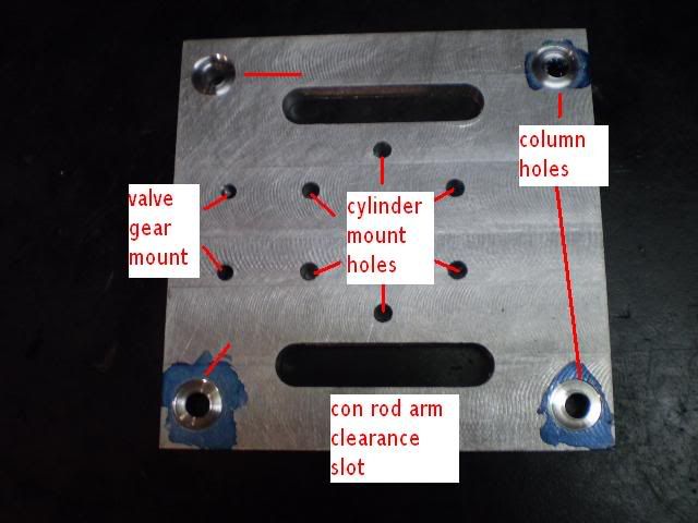
I started with the table. This is the upper deck of the engine upon which the cylinder block sits. This engine is also referred to as a Table engine for this reason. The table is drilled for mounting the cylinder block, the four support columns, tapped for mounting the valve gear and it is also milled to produce two slots through which the connecting rod assembly travels. This is one of those times when a picture is really worth a 1000 words so:
I counterbored the holes for the column connections by about 0.020 and the ends of the columns will have a register to fit into the recess. The same connection will be made from column to base. I dont like straight butt joints where theres going to be some side-to-side stresses.
I had a piece of 5/8 thick aluminum stock that was 8 wide and I used this for the base. Clearance holes for ¼ screws were drilled in the base for the support columns and the bearing blocks. I used an F drill for this purpose.
I used a 45º bevel cutter to form a bevel around the top of the base to finish off its appearance.
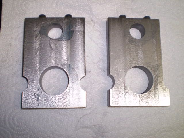
Next I worked on the bearing blocks. They have a nice scalloped look. I spent some time to layout a plan to avoid a lot of extra milling. The plans called for aluminum here but I wanted to make them in steel. The starting point for these was a ¾ x 3 bar of hot rolled steel. While milling a pair of blank blocks from this stock it occurred to me why castings were invented. Im going to be cutting away quite a bit of metal to get the finished product.
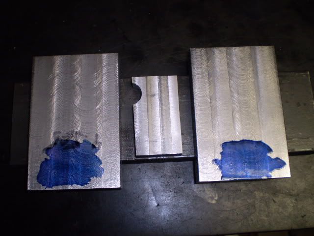
Well heres a lazy days work in this picture. Two blank bearing blocks are sitting on a piece of the parent stock. In the middle is a piece of steel scrap that I used to practice making the scalloped sides of the blocks. Luckily, cutting metal relaxes me.
Im not sure that the sequence of machining operations is all that important but at this point I have two fairly accurately milled rectangles of steel. The base mounting holes, the bearing hole, and the bearing cap mounting holes are the critical dimensions so I decided to do those first since I have true edges to work from. After these are machined its really just a matter of carving away a lot of metal to get the sculpted appearance.
The bottoms of the blocks were drilled/tapped for mounting to the base. The tops were drilled/tapped for the bearing caps. Here I diverged from the plans. The plans show the bearing block and the cap made as separate pieces. I used an approach that is common for casting models. That is, the bearing block and cap are made from a single piece of material. The cap mounting screw holes are drilled and tapped. The cap is cut off from the base, then the cap is screwed to the block and finally the hole for the bearing is drilled and bored.
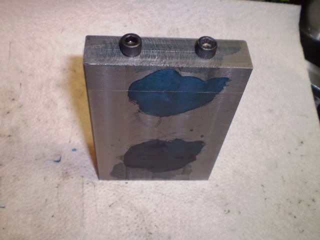
Two holes are bored in the bearing block. One for the crankshaft bushing, the other is an architectural detail. Bearing blocks that have been drilled and bored but not fully profiled are shown here:
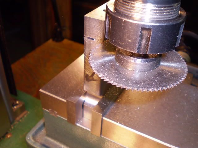
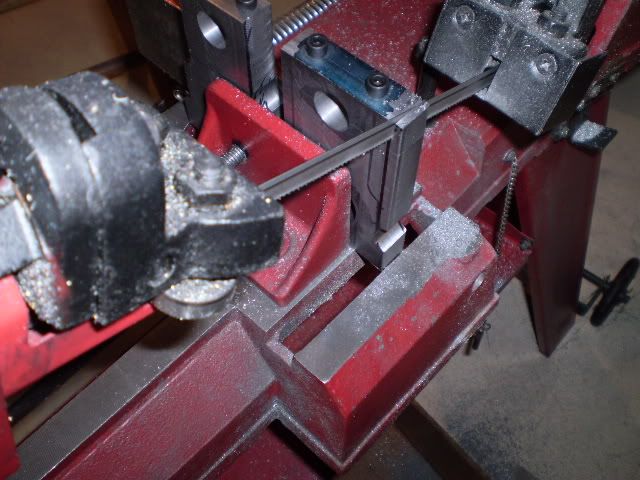
Now I needed to profile or scallop the edges of the blocks. This requires a combination of sawing, milling and drilling. I really prefer to saw excess material rather than mill it away for a number of reasons. But I once had a bad experience with the bandsaw blade becoming dull in the middle of a cut and wandering sharply into the workpiece. So I decided to mill away the excess on the first block. After many passes with the end mill I was convinced to do the second one using the bandsaw to remove most of the excess. Having finished the first block, I traced its outline on the second block and carefully watched the bandsaw blades progress. After sawing the edge was made true using an end mill to the final dimension.
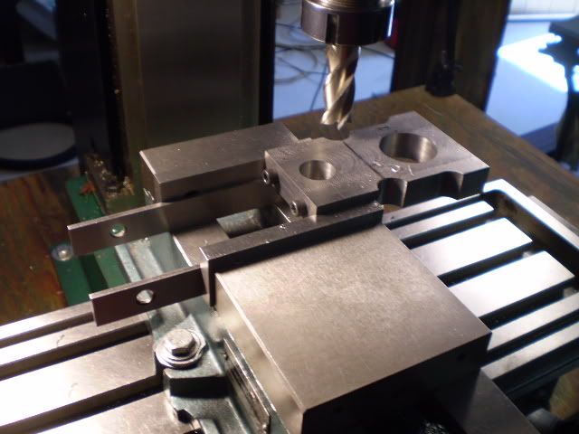
Scalloping the sides was accomplished with a ¾ centercutting end mill. I drilled this scallop into the workpiece by feeding it under the end mill in increments until I reached the desired end point.
Now I used either an end mill or the bandsaw to get rid of excess material. When I used the bandsaw, I made the side true with an end mill before cutting the other side.
I breathed a major sigh of relief when the bearing blocks were finished. The machining operations werent all that challenging but there was a lot of milling, deburring, sawing, deburring, drilling, deburring. I learned some time ago that you can skip the deburring steps in between. You are rewarded for doing this with some fine paperweights.
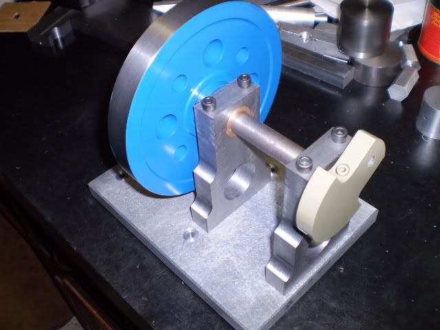
Ive mounted the bearing blocks on the base here.
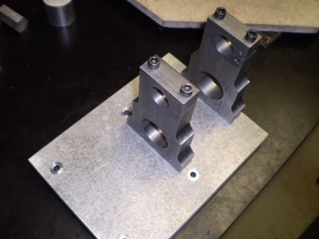
They seem like they came out OK but the real test is their function. So off to the shop to make a pair of bronze bushings. I had an piece of oilite bronze I picked up some years ago that was made for this project. The bushings were turned to fit each bearing block for a press fit. They turned out to be only a 0.001 apart in diameter. Since I can loosen the bearing caps pressing them in wasnt required. With the caps tightened I dont think the bushings will wander.
One of the real benefits of working at this hobby over time is that you accumulate a collection of dowels, engine parts, screws, bolts etc. of a variety of sizes. Need a dowel of diameter 0.812? Check the parts bin and youre bound to come up close.
Rummaging around I located a crankshaft with the proper diameter (5/8) and a spare flywheel to test out my alignment of these bearing blocks on the base. The arrangement is sort of an assault on the senses but I discovered that the flywheel turns effortlessly in the bearings. The actual crankshaft for this engine needs to be about 2 longer and the flywheel for this engine will be spoked, made from a casting.
So far each assembly functions smoothly on its own. Eventually all the assemblies will be connected and will need to work as designed. That test, the final exam, is still far off.
Now Im ready to work on the next phase of this base assembly, the support columns. When I finish those, Ill make the piston and piston rod. Then I can test the base, cylinder, connecting rod and crosshead assemblies all connected together, the mid-term exam.
Cheers,
Phil
This assembly consists of a base, four support columns, column finials, a table, a pair of bearing blocks with bushings and a pair of oil cups.
I started with the table. This is the upper deck of the engine upon which the cylinder block sits. This engine is also referred to as a Table engine for this reason. The table is drilled for mounting the cylinder block, the four support columns, tapped for mounting the valve gear and it is also milled to produce two slots through which the connecting rod assembly travels. This is one of those times when a picture is really worth a 1000 words so:
I counterbored the holes for the column connections by about 0.020 and the ends of the columns will have a register to fit into the recess. The same connection will be made from column to base. I dont like straight butt joints where theres going to be some side-to-side stresses.
I had a piece of 5/8 thick aluminum stock that was 8 wide and I used this for the base. Clearance holes for ¼ screws were drilled in the base for the support columns and the bearing blocks. I used an F drill for this purpose.
I used a 45º bevel cutter to form a bevel around the top of the base to finish off its appearance.
Next I worked on the bearing blocks. They have a nice scalloped look. I spent some time to layout a plan to avoid a lot of extra milling. The plans called for aluminum here but I wanted to make them in steel. The starting point for these was a ¾ x 3 bar of hot rolled steel. While milling a pair of blank blocks from this stock it occurred to me why castings were invented. Im going to be cutting away quite a bit of metal to get the finished product.
Well heres a lazy days work in this picture. Two blank bearing blocks are sitting on a piece of the parent stock. In the middle is a piece of steel scrap that I used to practice making the scalloped sides of the blocks. Luckily, cutting metal relaxes me.
Im not sure that the sequence of machining operations is all that important but at this point I have two fairly accurately milled rectangles of steel. The base mounting holes, the bearing hole, and the bearing cap mounting holes are the critical dimensions so I decided to do those first since I have true edges to work from. After these are machined its really just a matter of carving away a lot of metal to get the sculpted appearance.
The bottoms of the blocks were drilled/tapped for mounting to the base. The tops were drilled/tapped for the bearing caps. Here I diverged from the plans. The plans show the bearing block and the cap made as separate pieces. I used an approach that is common for casting models. That is, the bearing block and cap are made from a single piece of material. The cap mounting screw holes are drilled and tapped. The cap is cut off from the base, then the cap is screwed to the block and finally the hole for the bearing is drilled and bored.
Two holes are bored in the bearing block. One for the crankshaft bushing, the other is an architectural detail. Bearing blocks that have been drilled and bored but not fully profiled are shown here:
Now I needed to profile or scallop the edges of the blocks. This requires a combination of sawing, milling and drilling. I really prefer to saw excess material rather than mill it away for a number of reasons. But I once had a bad experience with the bandsaw blade becoming dull in the middle of a cut and wandering sharply into the workpiece. So I decided to mill away the excess on the first block. After many passes with the end mill I was convinced to do the second one using the bandsaw to remove most of the excess. Having finished the first block, I traced its outline on the second block and carefully watched the bandsaw blades progress. After sawing the edge was made true using an end mill to the final dimension.
Scalloping the sides was accomplished with a ¾ centercutting end mill. I drilled this scallop into the workpiece by feeding it under the end mill in increments until I reached the desired end point.
Now I used either an end mill or the bandsaw to get rid of excess material. When I used the bandsaw, I made the side true with an end mill before cutting the other side.
I breathed a major sigh of relief when the bearing blocks were finished. The machining operations werent all that challenging but there was a lot of milling, deburring, sawing, deburring, drilling, deburring. I learned some time ago that you can skip the deburring steps in between. You are rewarded for doing this with some fine paperweights.
Ive mounted the bearing blocks on the base here.
They seem like they came out OK but the real test is their function. So off to the shop to make a pair of bronze bushings. I had an piece of oilite bronze I picked up some years ago that was made for this project. The bushings were turned to fit each bearing block for a press fit. They turned out to be only a 0.001 apart in diameter. Since I can loosen the bearing caps pressing them in wasnt required. With the caps tightened I dont think the bushings will wander.
One of the real benefits of working at this hobby over time is that you accumulate a collection of dowels, engine parts, screws, bolts etc. of a variety of sizes. Need a dowel of diameter 0.812? Check the parts bin and youre bound to come up close.
Rummaging around I located a crankshaft with the proper diameter (5/8) and a spare flywheel to test out my alignment of these bearing blocks on the base. The arrangement is sort of an assault on the senses but I discovered that the flywheel turns effortlessly in the bearings. The actual crankshaft for this engine needs to be about 2 longer and the flywheel for this engine will be spoked, made from a casting.
So far each assembly functions smoothly on its own. Eventually all the assemblies will be connected and will need to work as designed. That test, the final exam, is still far off.
Now Im ready to work on the next phase of this base assembly, the support columns. When I finish those, Ill make the piston and piston rod. Then I can test the base, cylinder, connecting rod and crosshead assemblies all connected together, the mid-term exam.
Cheers,
Phil
Similar threads
- Replies
- 11
- Views
- 3K
- Replies
- 1
- Views
- 849
- Replies
- 0
- Views
- 798
- Replies
- 0
- Views
- 660