Hoglet build

Home Model Engine Machinist Forum

Help Support Home Model Engine Machinist Forum:

This site may earn a commission from merchant affiliate links, including eBay, Amazon, and others.

Trialnterror

Well-Known Member
Joined
Feb 3, 2013
Messages
88
Reaction score
47
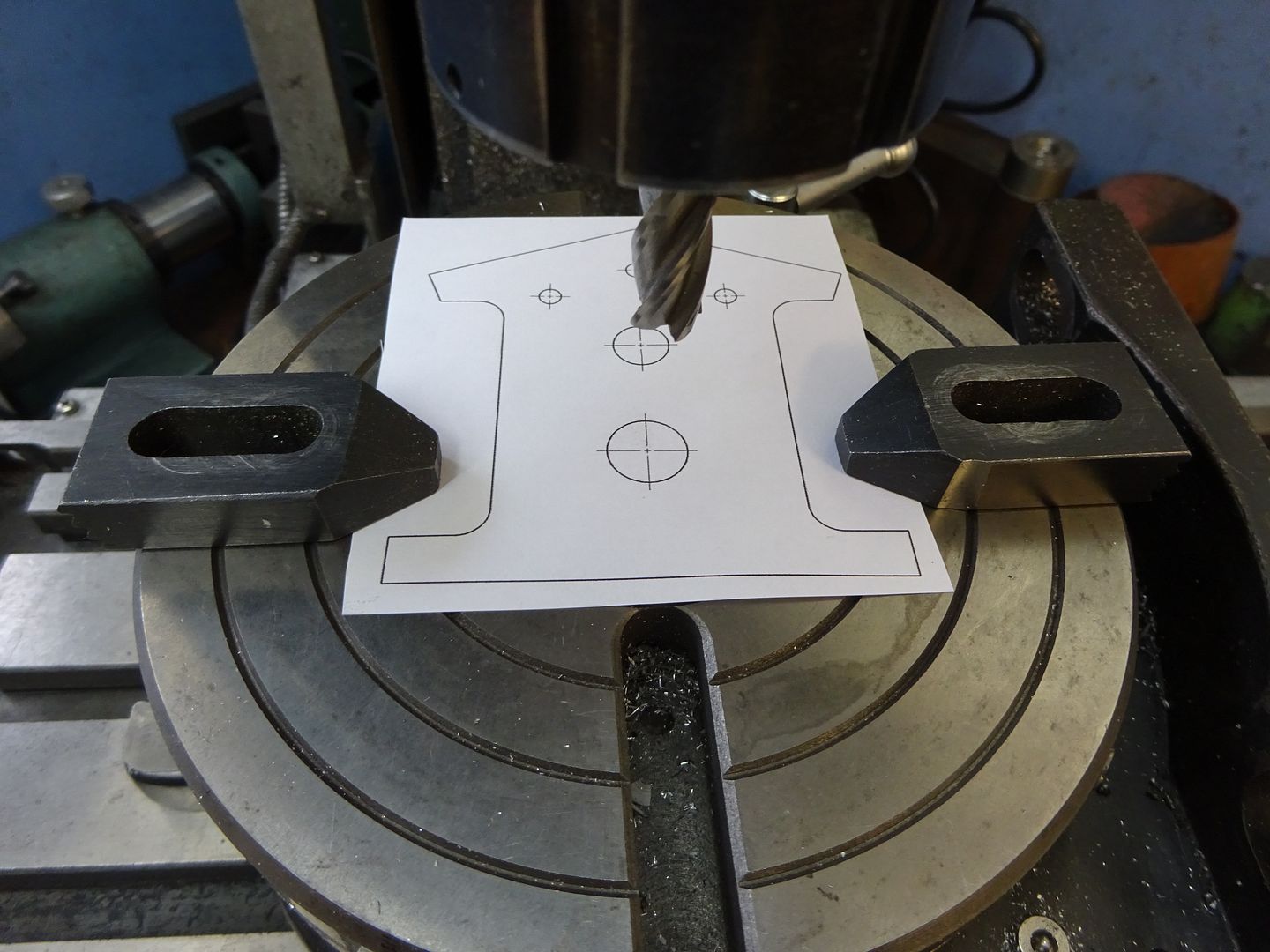
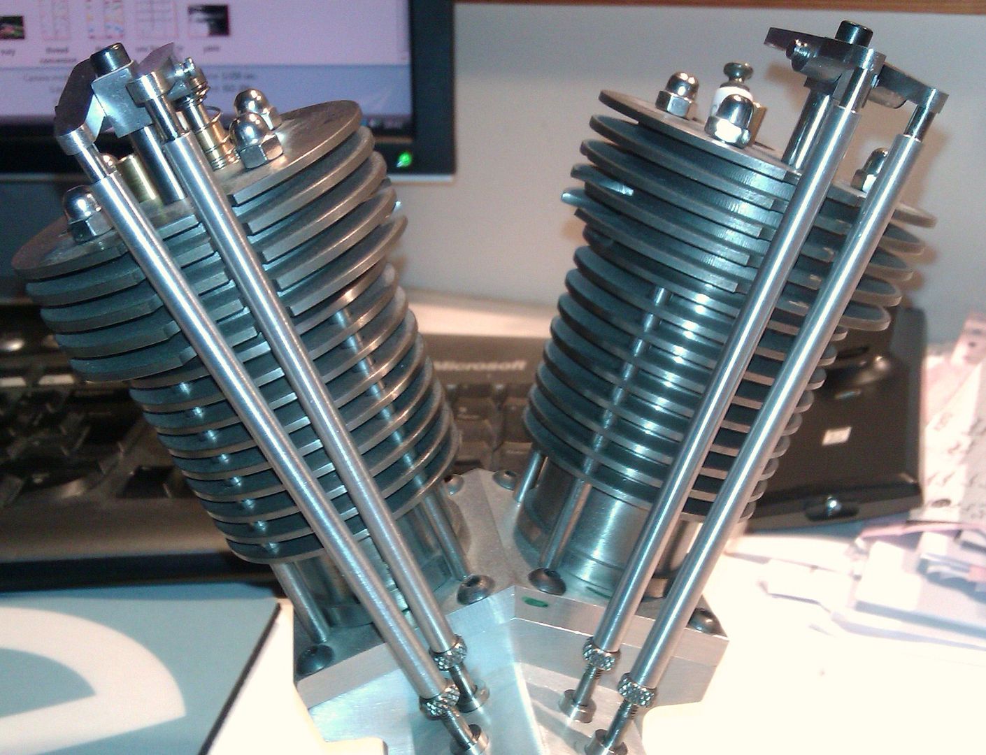
I've started the Hoglet I've started on the crank webs.
I've machined everything perfect except the final turn to dia.
It calls for R1.563 (3.126 dia) I'm at 3.108��

Question, do you think this is a big issue? Or when I build the rings just adjust them to fit?

image.jpg
 
It's only .018, just leave extra on the rings.

Ron
 
Got to love a Hoglet build, keep the photos coming :cool:

R
 
Question? When parting off the ring is it best to part right on dimension or leave some material and re-chuck the part and face it to dim? I haven't parted a lot of material?

image.jpg
 
Oh my boring bar is chatter city ? Can't seem to get a smooth cut? I ended up using a endmill ground into a boring bar? (It's hss and the boring bar is carbide is the the issue? Material is aluminum bronze )

I still have the question above too about parting off the ring?

image.jpg
 
Leave a little bit to clean up later, parting tools don't often gove a good finish and can wander a bit
 
When assembling the rings the instructions say "Machine the bronze wheels for
about 0.003" interference and heat them up to about 450 degrees F
for maybe an hour to assemble them. There will be some distor- tion and probably a little runout after they cool off, so allow for some finish turning on a mandrel. (Check out Dwight Giles’ method in Model Engine Builder #8) "

Well I didn't leave extra to put back in the lathe, would it be better to press them in to avoid any distortion?

Has anyone here assembled these before? (Especially having them to size and assembled them by heating the rings up?)
 
As the webs only make contact at the two ends there is a chance that as the ring cools or the web pressed in you will make the ring slightly oval shaped.

A lot will depend on how much of an interferance you have left but even if you did not allow for a finish cut at most you will only be taking a couple of thou off if they nee dcleaning up so that much undersize won't be the end of the world.

I pressed mine in to slightly warmed rings.
 
Thanks Jason,
would you use Loctite by chance also or just interference fit
(Guess it couldn't hurt?)
 
As you say a little drop won't hurt
 
I posted this on a new thread but I think I should stick to one thread....

How to accurately machine opposing angles

I've been machining as a Hobbie for prob 4 years. Everything I have learned has been by watching YouTube/--friends at work--/or forums.
That being said.....

I have done a couple engines a really small vtwin (kerzel I believe designed it)
A little easy steam engine by Mr.Pete222 and now the Hoglet.

I've successfully made the crank webs and flywheels and have attached them.

I am now building the crank case pieces. I have scoured the Internet and forums for accurately machine angles on the crankcase 21° apart from each other and I find zero zilch nothing. I started with cutting out on the bandsaw roughly the shape of the crankcase which I feel now was a mistake. So I started over with 2 pieces of material which I made the same. I then got my 0-0 and started milling out the sides. My next move is to drill and ream the 1/2" hole then pin the hole stand the parts (both pinned together) vertically on a 21° angle block and/or blocks to make 21° then reference off my 1/2" pin subtract .25 to get center? Then that would be my 0-0? I guess I would have to reference the top of the pin and the side to get accurately 0-0?

Any suggestions would be appreciated.

image.jpg
 
I did mine all on the rotary table, clamped the plate to it drilled & reamed the crank hole at 0-0 then offset everything from there. finally rotated table 21degrees and machined one top then rotated the opposite way to do the other top.

That way you just move 2.094 plus half the dia of the cutter you are using
 
Jason do you have any pictures of your setup on the rotary table?
I like the idea!
 
I did mine before I started taking in progress photos but this should give you the idea. It makes things a whole lot easier if the crank hole is central to the rotary table as all sizes can be set from that.

Clock the rotary table below the spindle and zero your handwheels or DRO. Clamp your piece of 1/4" plate in position with some sacrificial packing below. In this position drill & ream the 0.500" and 0.375" holes and also do the three holes for the cam follower bracket. The bottom can also be done by moving the Y-axis 0.938 plus half tool diameter.

DSC01247_zps6hq872pp.jpg


Now rotate the table to 21 degrees and cut the first top face finishing with the spindle 2.093 plus half tool dia away in the y-axis. Not shown but also do the top return to leave the edge 1.607"

DSC01248_zpsvfmwztif.jpg


Now rotate the table the opposite way to 339degrees (360-21) taking up any backlash and make the same two cuts to complete the other side.

DSC01250_zpshh01m1fs.jpg


Reposition the clamps one at a time making sure the part does not move, you can use the 3/8" hole if a clamp won't fit at the top. Reset rotary table to 0degrees and just mill the two features at the sides.

DSC01251_zpsmshwonf2.jpg


If you get it right then when the two top plates are fitted it should look something like this

IMAG1195_zps48xgri1f.jpg


J
 

Latest posts

Back
Top