Looks great! It's always really cool when they run on real steam.
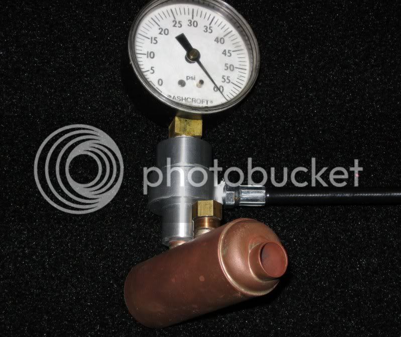
You've gotta rig yourself a pressure gauge so you can see what's up when testing the safety and burner tuning-- doesn't have to be a little one, mine was a surpluscenter 200 PSI model, same as available at hardware stores for $15-20. there's not a pic of it in my thread except on the pump, but it's featured in the safety-test video- http://www.homemodelenginemachinist.com/index.php?action=dlattach;topic=2049.0;attach=1603 the pigtail pipe is to prevent live steam from damaging the works-- a U-bend would probably work as well.
You've gotta rig yourself a pressure gauge so you can see what's up when testing the safety and burner tuning-- doesn't have to be a little one, mine was a surpluscenter 200 PSI model, same as available at hardware stores for $15-20. there's not a pic of it in my thread except on the pump, but it's featured in the safety-test video- http://www.homemodelenginemachinist.com/index.php?action=dlattach;topic=2049.0;attach=1603 the pigtail pipe is to prevent live steam from damaging the works-- a U-bend would probably work as well.