vlmarshall
Well-Known Member
- Joined
- Dec 28, 2008
- Messages
- 1,138
- Reaction score
- 1
Shred's build of the Cracker (April's Project Of The Month winner) has convinced me to build my own. I haven't wanted to start a thread on it, mainly because of the craftsmanship standards that I see on here. :bow:
Still, here's my progress so far.
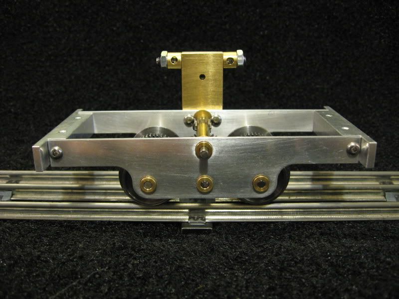
The first thing I had to do was come up with the gears, as the pitch diameter would set the axle and crankshaft spacing. I followed Shred's advice, and used RC pinion gears from Robinson Racing, as I've used their products many times in my younger days.
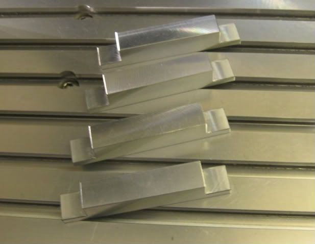
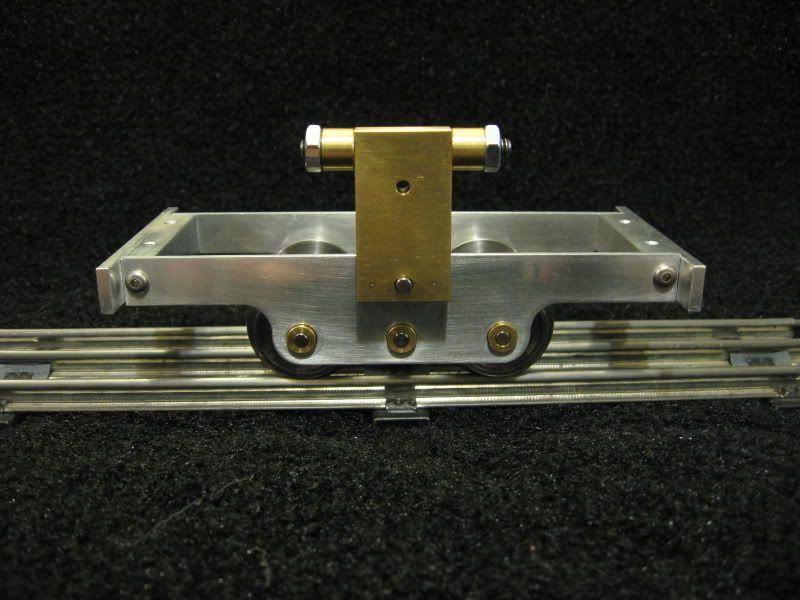
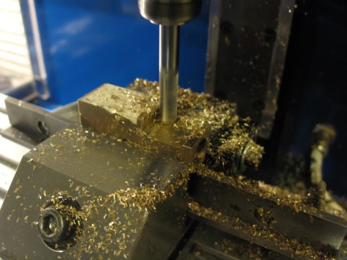
For a lot of this build, I'm "cheating" and using a CNC Sherline mill at home, and a manual Hardinge lathe at work. Cutting out the side frames was simple enough, and I decided to build TWO locomotives, one for myself, and one for my dad.
Here's the first one being cut out on my little Sherline at home.
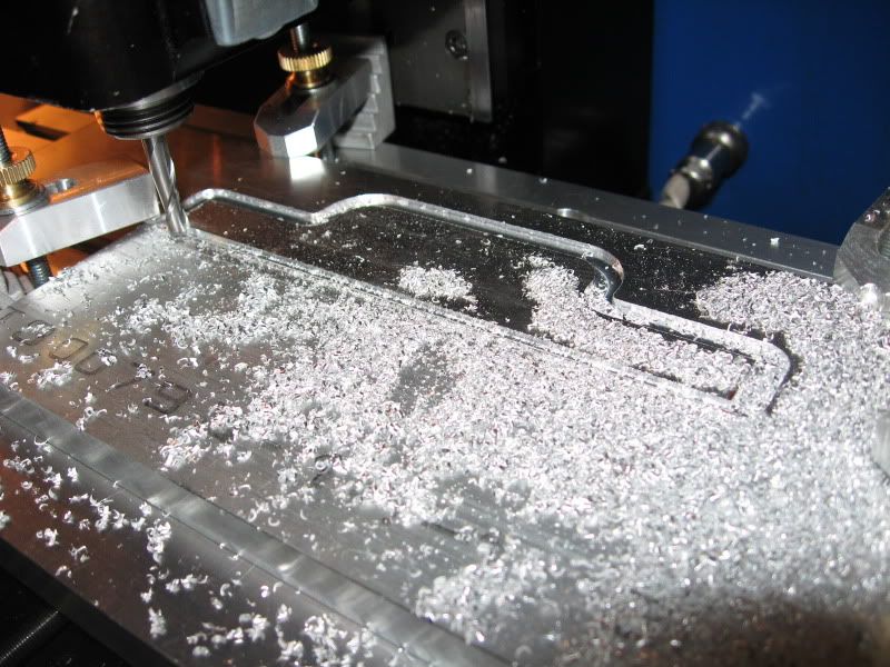
This is too easy, so far. The loco frames are 10mm longer, 5mm added to each end, to make room for a slightly longer boiler, and more room on the footplate as well. Originally I was going to add all 10mm to one end, and move the fuel tank under the footplate and between the frame rails, as I've read elsewhere online, but decided against it, at least for THIS build. ;D
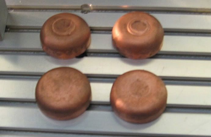
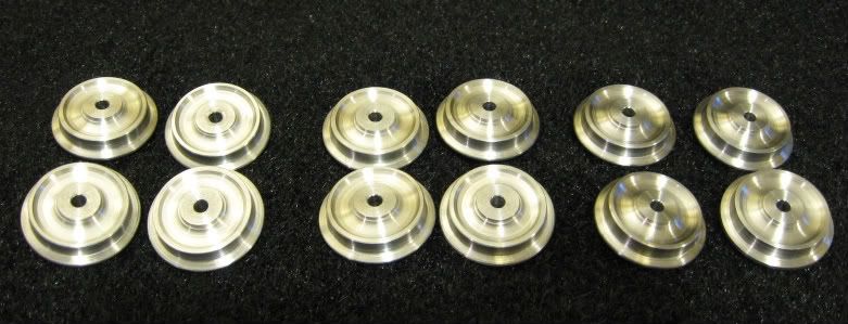
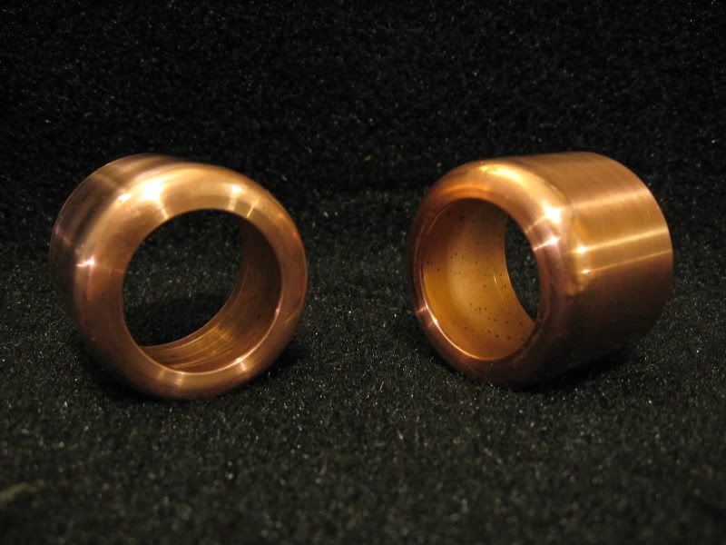
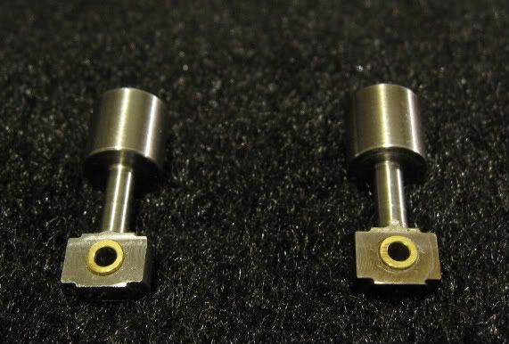
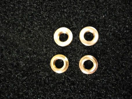
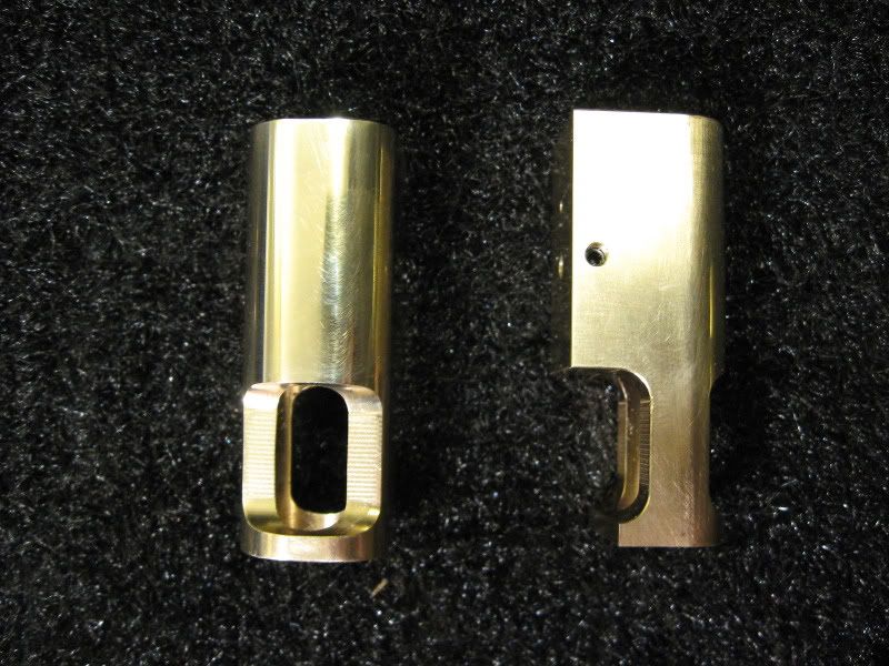
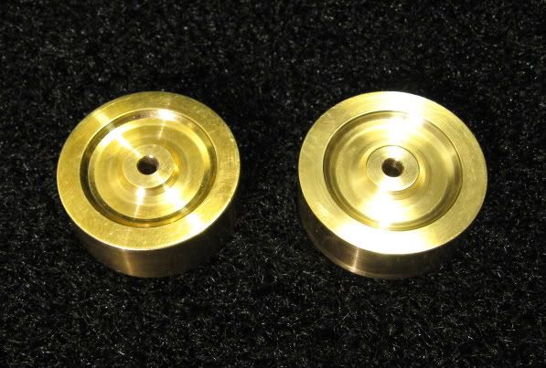
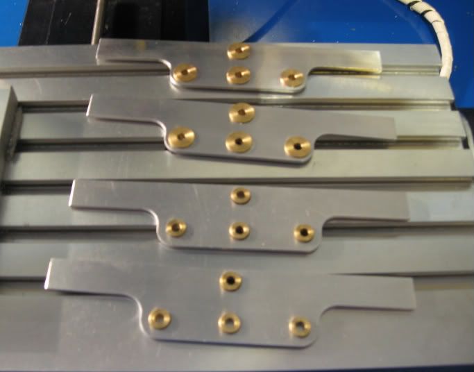
I turned two sets of bushings, again diverting from the plans, and making all 8 bushings to the same dimensions.
Here they are in place.
Still, here's my progress so far.
The first thing I had to do was come up with the gears, as the pitch diameter would set the axle and crankshaft spacing. I followed Shred's advice, and used RC pinion gears from Robinson Racing, as I've used their products many times in my younger days.
For a lot of this build, I'm "cheating" and using a CNC Sherline mill at home, and a manual Hardinge lathe at work. Cutting out the side frames was simple enough, and I decided to build TWO locomotives, one for myself, and one for my dad.
Here's the first one being cut out on my little Sherline at home.
This is too easy, so far.
The loco frames are 10mm longer, 5mm added to each end, to make room for a slightly longer boiler, and more room on the footplate as well. Originally I was going to add all 10mm to one end, and move the fuel tank under the footplate and between the frame rails, as I've read elsewhere online, but decided against it, at least for THIS build. ;DI turned two sets of bushings, again diverting from the plans, and making all 8 bushings to the same dimensions.
Here they are in place.