
You are using an out of date browser. It may not display this or other websites correctly.
You should upgrade or use an alternative browser.
You should upgrade or use an alternative browser.
Elmer's Pumping Engine
- Thread starter Sshire
- Start date


Help Support Home Model Engine Machinist Forum:
This site may earn a commission from merchant affiliate
links, including eBay, Amazon, and others.
Philjoe5
Well-Known Member
- Joined
- Jul 12, 2007
- Messages
- 1,727
- Reaction score
- 321
Hi Stan,
I have a Oliver Die Filer. Acquired from a friend. In very good condition. I've used it a few times and am getting some experience with it.

A nice tool for those of us that are "file challenged"")
Cheers,
Phil
I have a Oliver Die Filer. Acquired from a friend. In very good condition. I've used it a few times and am getting some experience with it.

A nice tool for those of us that are "file challenged"
Cheers,
Phil
Sshire
Well-Known Member
- Joined
- Jun 29, 2011
- Messages
- 936
- Reaction score
- 259
Valve and Valve Nut
It's tiny parts day. The valves are .25" x .28". The valve nuts are .25" x .125". Nothing out of the ordinary as far as milling. Just smaller moves.
Optivisor on. Let's start.
The bottom of the valve has a recess. A .125" end mill and just cranking from DRO coordinates to the next set. The air blower really is a help in clearing chips so I can see what's happening.
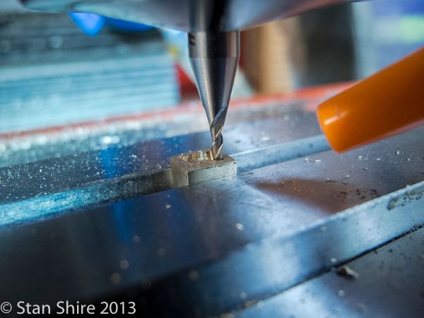
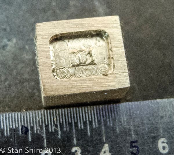
Looks a bit rough at this magnification.
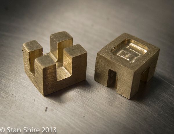
Turning the valve to the upper side, there are cross grooves. One for the valve rod and the other for the valve nut. The 2-56 thread on the valve rod screws into the nut. This gives adjustment for valve position over the ports in the cylinder.
I milled the slots in three passes. Increasing the depth each time as I was hoping to not break the end mill.
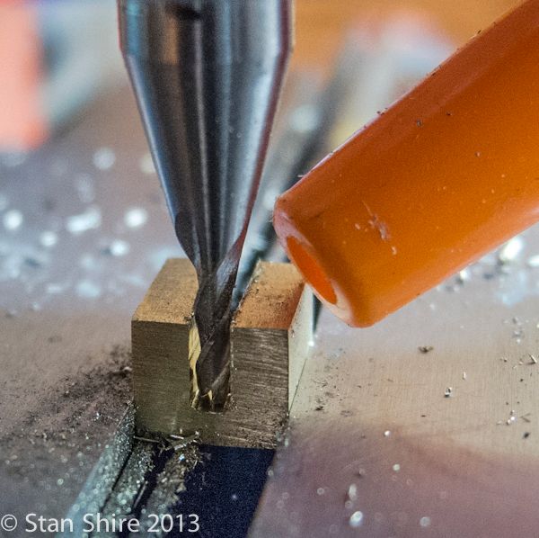
Two more parts completed. No end mills were harmed in the making of these valves.
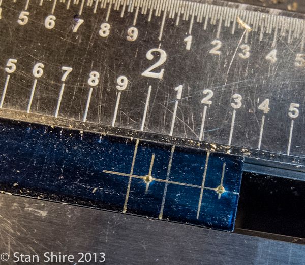
Now to the valve nuts. a piece of .0625 thick brass; milled to .25" width. I did a layout of both nuts and center popped the hole locations. These will be drilled and tapped 2-56. The optical center punch worked perfectly, as I did hit my scribe lines. I had milled the right end square so I'd only have to file one side.
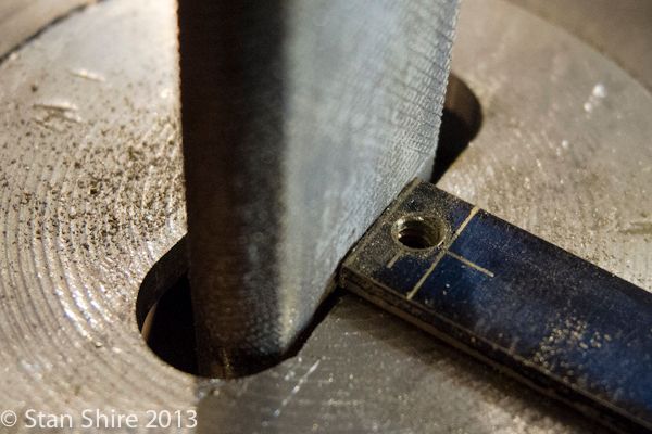
After the tapping, I cut one nut off with a jewelers saw. Then a visit to Oliver to file the next piece to the scribe line.
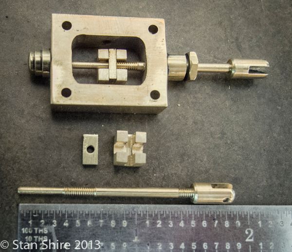
So, here are today's parts. One set threaded onto the valve rod in the steam chest.
Next time, the Top and Bottom steam cylinder heads.
It's tiny parts day. The valves are .25" x .28". The valve nuts are .25" x .125". Nothing out of the ordinary as far as milling. Just smaller moves.
Optivisor on. Let's start.
The bottom of the valve has a recess. A .125" end mill and just cranking from DRO coordinates to the next set. The air blower really is a help in clearing chips so I can see what's happening.


Looks a bit rough at this magnification.
Turning the valve to the upper side, there are cross grooves. One for the valve rod and the other for the valve nut. The 2-56 thread on the valve rod screws into the nut. This gives adjustment for valve position over the ports in the cylinder.
I milled the slots in three passes. Increasing the depth each time as I was hoping to not break the end mill.

Two more parts completed. No end mills were harmed in the making of these valves.

Now to the valve nuts. a piece of .0625 thick brass; milled to .25" width. I did a layout of both nuts and center popped the hole locations. These will be drilled and tapped 2-56. The optical center punch worked perfectly, as I did hit my scribe lines. I had milled the right end square so I'd only have to file one side.

After the tapping, I cut one nut off with a jewelers saw. Then a visit to Oliver to file the next piece to the scribe line.

So, here are today's parts. One set threaded onto the valve rod in the steam chest.

Next time, the Top and Bottom steam cylinder heads.
Sshire
Well-Known Member
- Joined
- Jun 29, 2011
- Messages
- 936
- Reaction score
- 259
Steam Cylinder Heads, Pistons, Rods, Steam Manifold
Took time off from the engine to get the new bandsaw uncrated, disassembled, cleaned, hand carried in pieces down to the shop, reassembled and tuned-up with a Starrett blade. Cuts dead straight and very nice finish. Haven't named it yet, but I'm working on it.
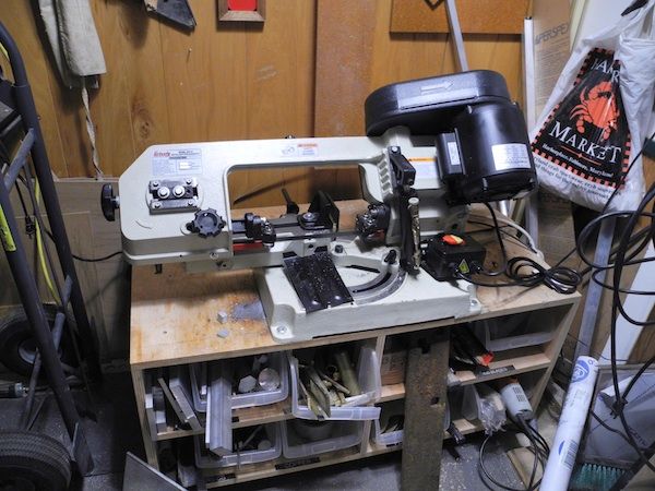
That's it for the machine porn. Back to the engine.
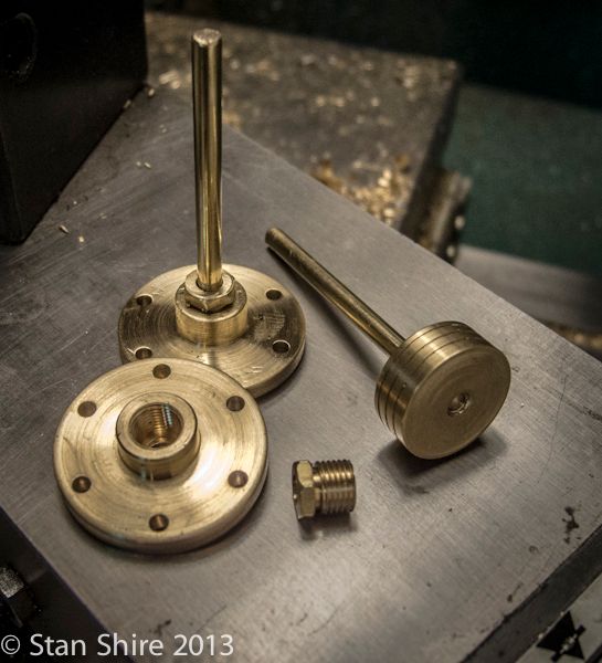
The next parts are the steam cylinder heads. The top heads are flat with a 1/32" locating spigot on the back side. The bottom heads are drilled and tapped for the connecting rod pack nut.
I started with a brass round, turned to the needed diameter. I'm very happy with the finish from the round bit in the tangential tool holder. Unless I'm turning into a corner (as in the second pic), this tool is the one I like to use.
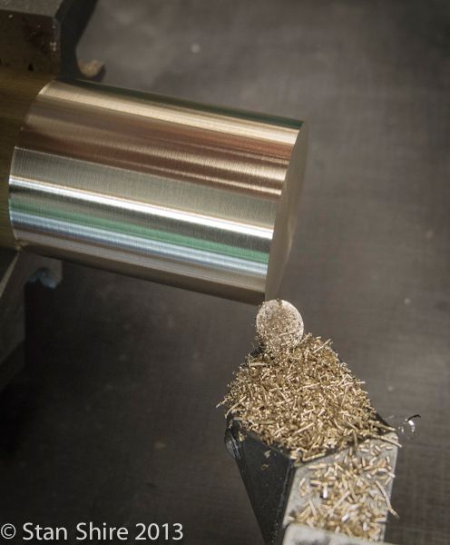
Turning and parting went without issue and then drilling and tapping for the piston rod in the lower heads.
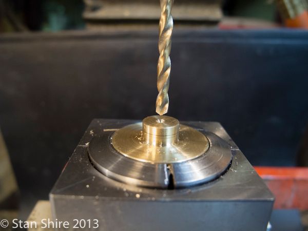
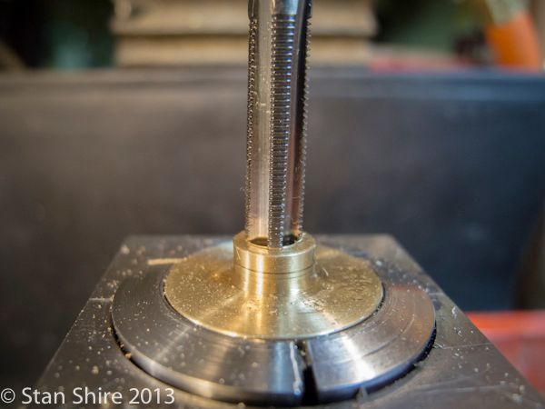
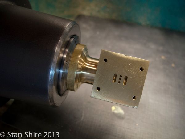
The heads then (still in the 5C collet) were locked into a square collet block and moved to the mill for the bolt hole circle dance. Appropriate numbers were entered into the DRO and it's then just, DRO to Hole 1; display to 0,0. Hole2; display to 0,0. Repeat for all 6 holes. Replace part in collet. Do it all again.
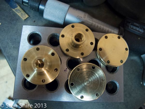
On to the pistons. Another piece of brass round, turned until it fits almost nicely.
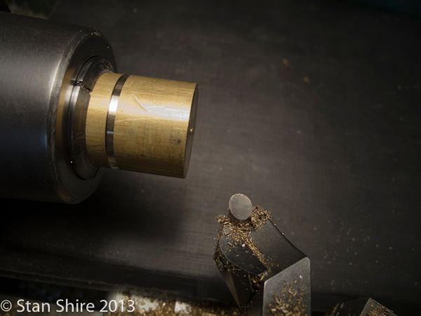
Then the Sorcerer's Powder. I got the sample kit: 1 tin each of 4, non-ferrous grits. Looks to be a lifetime supply. Mix a bit of the powder in some oil.
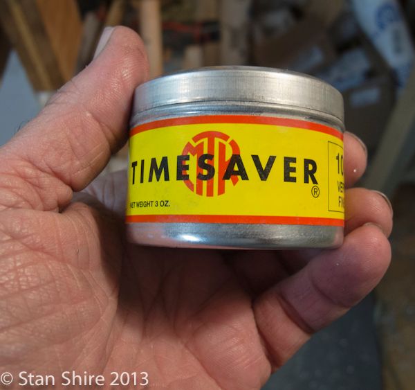
The oil-powder mix is spread onto the piston. Lathe at slow speed and gently lap the cylinder until the powder stops cutting. The difference between this stuff and Clover is that Timesaver breaks down as it works until it will no longer cut.
The instructions say to clean the parts with "Stoddard's Solvent." It took a bit a Googling until I found that Mineral Spirits are the same thing.
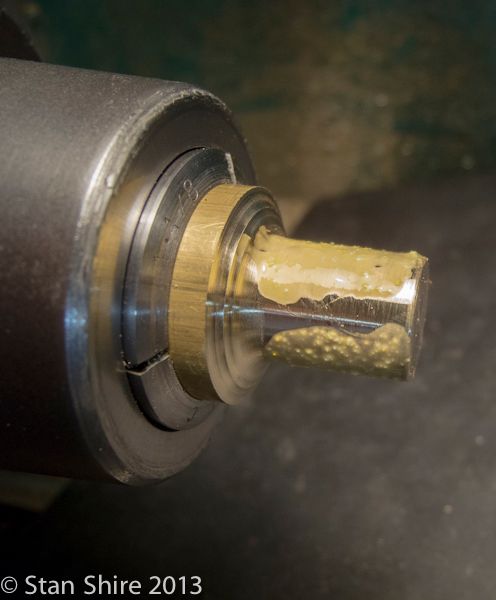
I'm know that this isn't the recommended way to lap a cylinder and piston, but the piston now moves through the cylinder with no binding and, a thumb on the end will hold it in position until released.
Oil grooves cut into the piston. It was then drilled and tapped for the piston rod and parted off.
Some .125 brass rod in a collet, threaded and done.
Hex rod in a 5C collet to make the two packing nuts. Just turned to diameter and threaded.
The finished nut threaded into the lowed head then both are drilled and reamed. I'm probably the last person on the forums to realize that reaming these "in place" will result in no binding. I saw a picture of this last week on Jo's demonstration engine. Head slap ensued followed by "Duh."
I now owe Jo TWO dinners.
More pieces completed. Of course, filing, sanding and polishing are in my future.
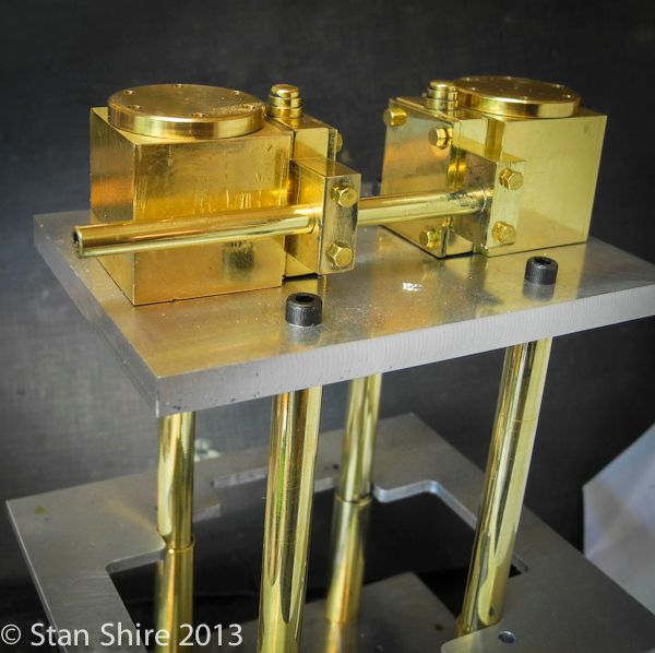
Next in line is the Steam Intake Manifold. A bit of brass from the bin and 3/16 brass tubing.
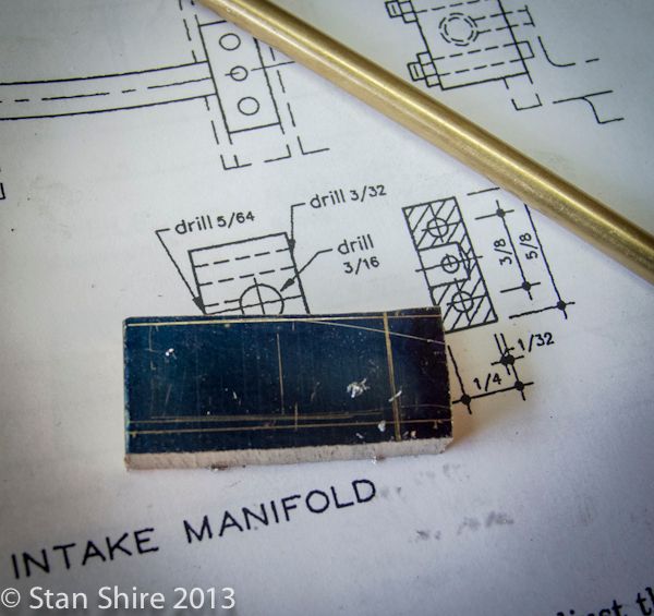
Totally unexciting squaring, cutting, drilling resulted in these.
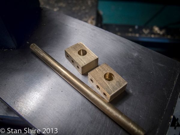
One of the manifold blocks has a through hole for the steam/air tubing. The other is a stopped hole.
That block is silver soldered to the tubing.

After soldering, I soaked the assembly in citric acid (sour salts) for 10 minutes or so. Now to get rid of the "pink" color. Don't know if this is correct but I've read that the pink color is copper migrating to the surface of the brass.
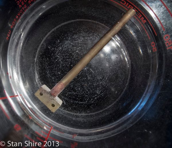
The secret formula to remove the pink color and get the brass color back is: 3 parts white vinegar and 2 parts hydrogen peroxide. About a 15 minute soak seems to do it. Be careful of leaving it in too long as it will eventually begin to attack the metal.
I just did a quick assembly to be sure the manifold fits. Filing, sanding. Filing sanding. All is well.
Took time off from the engine to get the new bandsaw uncrated, disassembled, cleaned, hand carried in pieces down to the shop, reassembled and tuned-up with a Starrett blade. Cuts dead straight and very nice finish. Haven't named it yet, but I'm working on it.

That's it for the machine porn. Back to the engine.
The next parts are the steam cylinder heads. The top heads are flat with a 1/32" locating spigot on the back side. The bottom heads are drilled and tapped for the connecting rod pack nut.
I started with a brass round, turned to the needed diameter. I'm very happy with the finish from the round bit in the tangential tool holder. Unless I'm turning into a corner (as in the second pic), this tool is the one I like to use.

Turning and parting went without issue and then drilling and tapping for the piston rod in the lower heads.


The heads then (still in the 5C collet) were locked into a square collet block and moved to the mill for the bolt hole circle dance. Appropriate numbers were entered into the DRO and it's then just, DRO to Hole 1; display to 0,0. Hole2; display to 0,0. Repeat for all 6 holes. Replace part in collet. Do it all again.

On to the pistons. Another piece of brass round, turned until it fits almost nicely.

Then the Sorcerer's Powder. I got the sample kit: 1 tin each of 4, non-ferrous grits. Looks to be a lifetime supply. Mix a bit of the powder in some oil.

The oil-powder mix is spread onto the piston. Lathe at slow speed and gently lap the cylinder until the powder stops cutting. The difference between this stuff and Clover is that Timesaver breaks down as it works until it will no longer cut.
The instructions say to clean the parts with "Stoddard's Solvent." It took a bit a Googling until I found that Mineral Spirits are the same thing.


I'm know that this isn't the recommended way to lap a cylinder and piston, but the piston now moves through the cylinder with no binding and, a thumb on the end will hold it in position until released.
Oil grooves cut into the piston. It was then drilled and tapped for the piston rod and parted off.

Some .125 brass rod in a collet, threaded and done.

Hex rod in a 5C collet to make the two packing nuts. Just turned to diameter and threaded.

The finished nut threaded into the lowed head then both are drilled and reamed. I'm probably the last person on the forums to realize that reaming these "in place" will result in no binding. I saw a picture of this last week on Jo's demonstration engine. Head slap ensued followed by "Duh."
I now owe Jo TWO dinners.

More pieces completed. Of course, filing, sanding and polishing are in my future.

Next in line is the Steam Intake Manifold. A bit of brass from the bin and 3/16 brass tubing.

Totally unexciting squaring, cutting, drilling resulted in these.

One of the manifold blocks has a through hole for the steam/air tubing. The other is a stopped hole.
That block is silver soldered to the tubing.

After soldering, I soaked the assembly in citric acid (sour salts) for 10 minutes or so. Now to get rid of the "pink" color. Don't know if this is correct but I've read that the pink color is copper migrating to the surface of the brass.

The secret formula to remove the pink color and get the brass color back is: 3 parts white vinegar and 2 parts hydrogen peroxide. About a 15 minute soak seems to do it. Be careful of leaving it in too long as it will eventually begin to attack the metal.

I just did a quick assembly to be sure the manifold fits. Filing, sanding. Filing sanding. All is well.

Sshire
Well-Known Member
- Joined
- Jun 29, 2011
- Messages
- 936
- Reaction score
- 259
Yokes and Eccentric Straps
I've been thinking about how to produce these yokes since I first saw the plans.
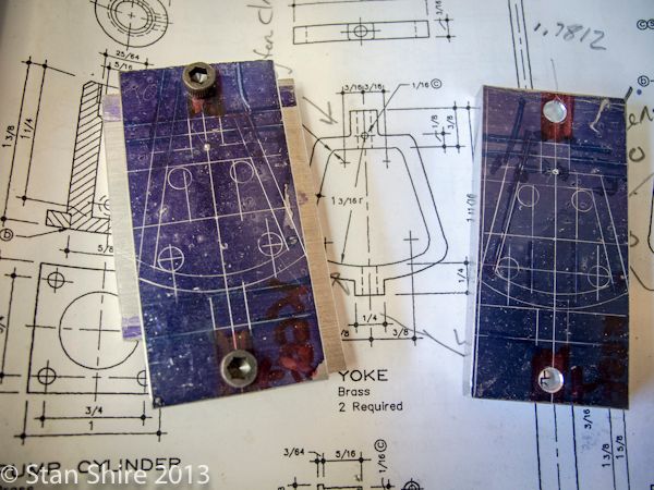
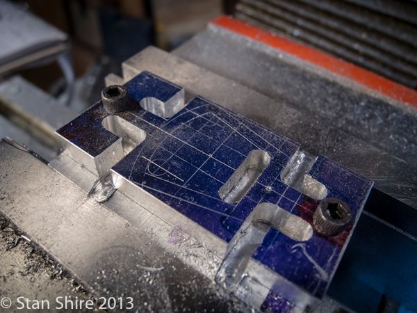
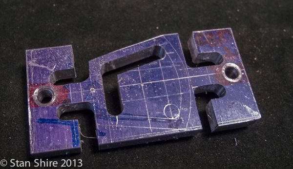
My plan was to layout both yokes, machine the straight cuts in the vise and then move to the rotary table for the arcs.
Rather than do the setups twice, I made a fixture to hold the yoke pieces with screws. The fixture would also be a sacrificial base for the milling.
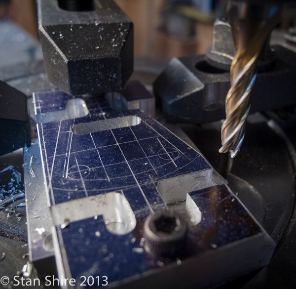
Here's the drawing and the two layouts. The left one is screwed to the base.
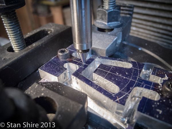
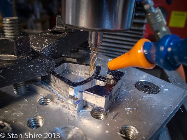
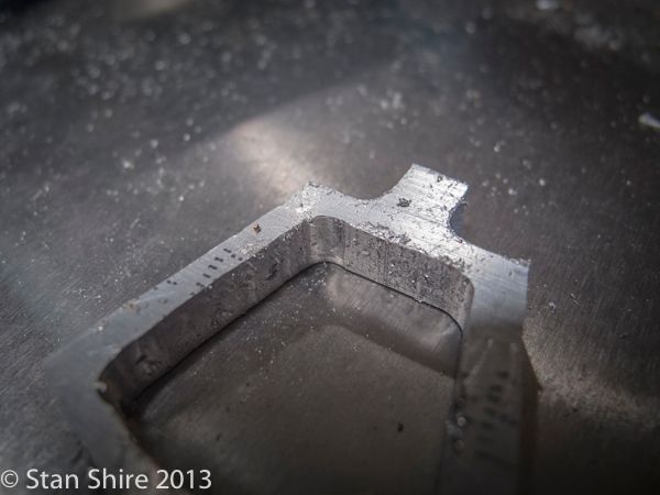
The first cut is always the hardest for me. I used a 3/16" end mill, plenty of cutting fluid and the air nozzle blowing chips out of the cut. I wanted to do everything in one pass (.25 depth)
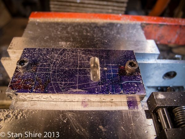
All of the horizontal and vertical cuts on piece #1. I've got a small vise stop just out of the picture in case I needed to move the fixture. No need. Just unscrewed the first part and replaced it with the other one. I had saved each set of XY coordinates in the DRO.
With those cuts done, I replaced the vise with the 6" rotary table and centered it.
I just kept rotating the table until the angled sides lines up with the mill's X axis. Trial and error.

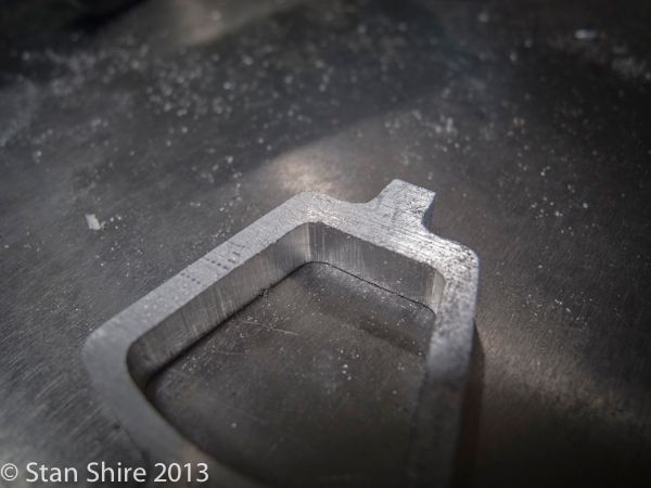
After both angles were cut on both parts, the radius cuts were next.
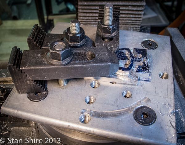
Each piece had a pop mark at the center of rotation (between the clamp and the straight cut in this picture) so the pointy end of an edge finder was chucked up and placed in the pop mark. With that holding the part in position, I clamped the part to the rotary table. Now I moved the X axis to the radius to be cut. Crank the table, cut both arcs, replace the part, repeat.
You never have too many clamps
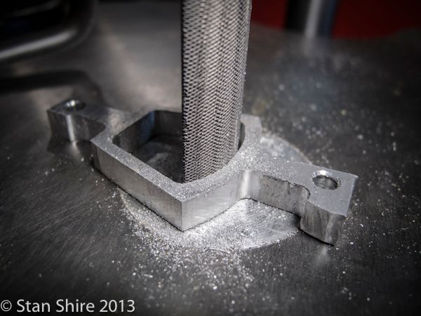
This was the perfect opportunity to give the modified half-round files a workout. I cut off the file's tang and belt sanded the teeth off both ends (to prevent damage to Oliver's clamps.)
Switched to the flat file with rounded ends for this section.
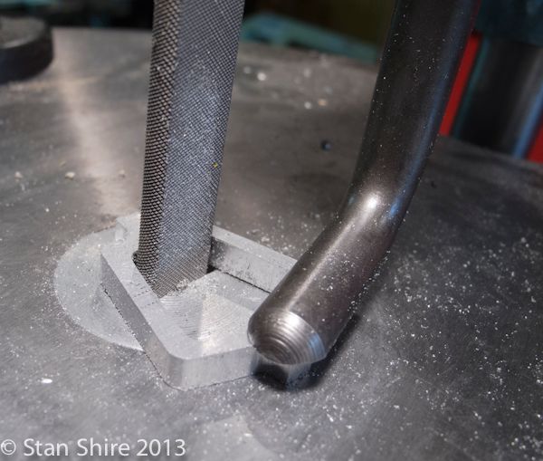
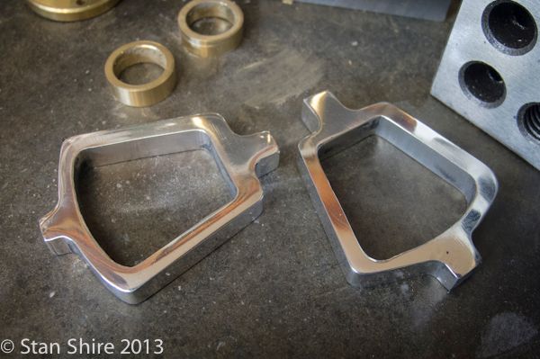
Before and after. About 2 minutes with Oliver.
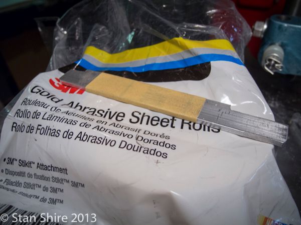
Since that went so well, I made some sanding files.
Some holes yet to be drilled, but enough for now.
The Eccentric Straps
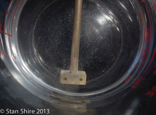
I find it easier to make two-piece eccentric straps: the ring and the strap.
Start with what happened to be in the collet chuck and turn it down to 9/16" per Elmer.
Center drill, drill, ream and part off.
The parted-off ring fitted into a collet then into a collet block. The flat strap will be silver soldered to the ring. A .064 slitting saw cutting a bit deeper than ½ of the ring's wall.
Looks like this
The straps were layed out on .0625 brass and then tapered.
The almost-completed parts after soldering, a citric acid soak and then into the secret formula to remove the pink color (not so much a secret after the last post)
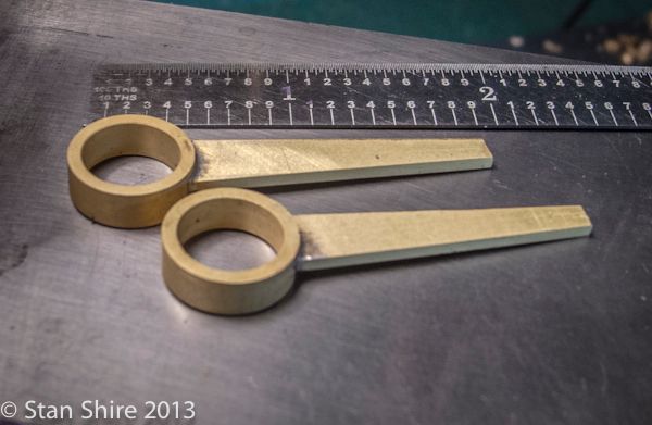
Some filing and sanding to do.
I'm hoping to do the eccentrics tomorrow and, depending on how that goes, some as-yet-to-be-determined part. There are plenty more but the list gets shorter.
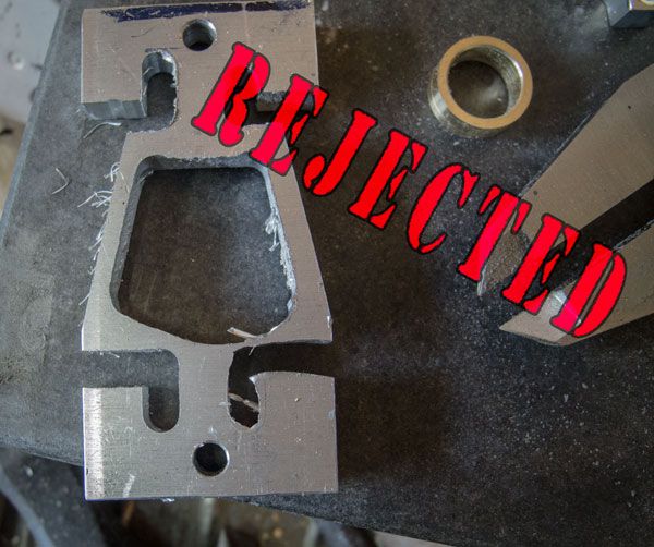
Epilogue and note to self.
"When everything is going really well and you are on the last cut of about 12, REMEMBER TO TIGHTEN THE DAMN CLAMPS!"
I've been thinking about how to produce these yokes since I first saw the plans.
My plan was to layout both yokes, machine the straight cuts in the vise and then move to the rotary table for the arcs.
Rather than do the setups twice, I made a fixture to hold the yoke pieces with screws. The fixture would also be a sacrificial base for the milling.
Here's the drawing and the two layouts. The left one is screwed to the base.

The first cut is always the hardest for me. I used a 3/16" end mill, plenty of cutting fluid and the air nozzle blowing chips out of the cut. I wanted to do everything in one pass (.25 depth)

All of the horizontal and vertical cuts on piece #1. I've got a small vise stop just out of the picture in case I needed to move the fixture. No need. Just unscrewed the first part and replaced it with the other one. I had saved each set of XY coordinates in the DRO.

With those cuts done, I replaced the vise with the 6" rotary table and centered it.
I just kept rotating the table until the angled sides lines up with the mill's X axis. Trial and error.


After both angles were cut on both parts, the radius cuts were next.
Each piece had a pop mark at the center of rotation (between the clamp and the straight cut in this picture) so the pointy end of an edge finder was chucked up and placed in the pop mark. With that holding the part in position, I clamped the part to the rotary table. Now I moved the X axis to the radius to be cut. Crank the table, cut both arcs, replace the part, repeat.


You never have too many clamps

This was the perfect opportunity to give the modified half-round files a workout. I cut off the file's tang and belt sanded the teeth off both ends (to prevent damage to Oliver's clamps.)

Switched to the flat file with rounded ends for this section.

Before and after. About 2 minutes with Oliver.


Since that went so well, I made some sanding files.

Some holes yet to be drilled, but enough for now.

The Eccentric Straps
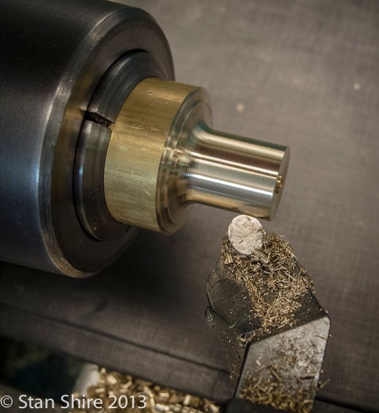
I find it easier to make two-piece eccentric straps: the ring and the strap.
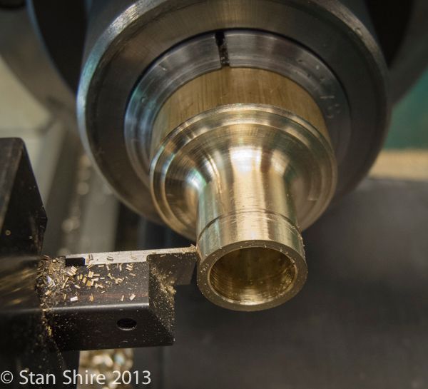
Start with what happened to be in the collet chuck and turn it down to 9/16" per Elmer.

Center drill, drill, ream and part off.

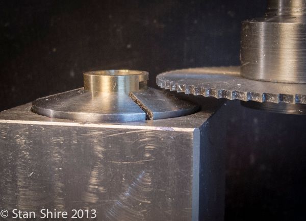
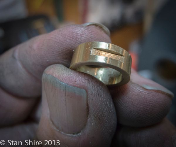
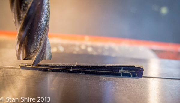
The parted-off ring fitted into a collet then into a collet block. The flat strap will be silver soldered to the ring. A .064 slitting saw cutting a bit deeper than ½ of the ring's wall.

Looks like this

The straps were layed out on .0625 brass and then tapered.

The almost-completed parts after soldering, a citric acid soak and then into the secret formula to remove the pink color (not so much a secret after the last post)

Some filing and sanding to do.
I'm hoping to do the eccentrics tomorrow and, depending on how that goes, some as-yet-to-be-determined part. There are plenty more but the list gets shorter.
Epilogue and note to self.
"When everything is going really well and you are on the last cut of about 12, REMEMBER TO TIGHTEN THE DAMN CLAMPS!"

jwcnc1911
-jwcnc191
- Joined
- Mar 19, 2013
- Messages
- 603
- Reaction score
- 86
Love your pictures! So clear and of such good subjects, even that reject (I was beginning to wander if you were perfect).
Did I mention, holy crap I want one of those filers? Forget eBay, every one on there is way to proud of the one they have.
Did I mention, holy crap I want one of those filers? Forget eBay, every one on there is way to proud of the one they have.
Sshire
Well-Known Member
- Joined
- Jun 29, 2011
- Messages
- 936
- Reaction score
- 259
Eccentric
Yes, you're right. I could have done the eccentric in the 4-jaw, but I thought I'd show another way without using an indicator OR a 4-jaw.
Machining the eccentric in the Keats Angle Plate has the advantage of being able to remove the part for another operation and then return it without indicating again. Also, multiple parts (as in two eccentrics) work just fine.
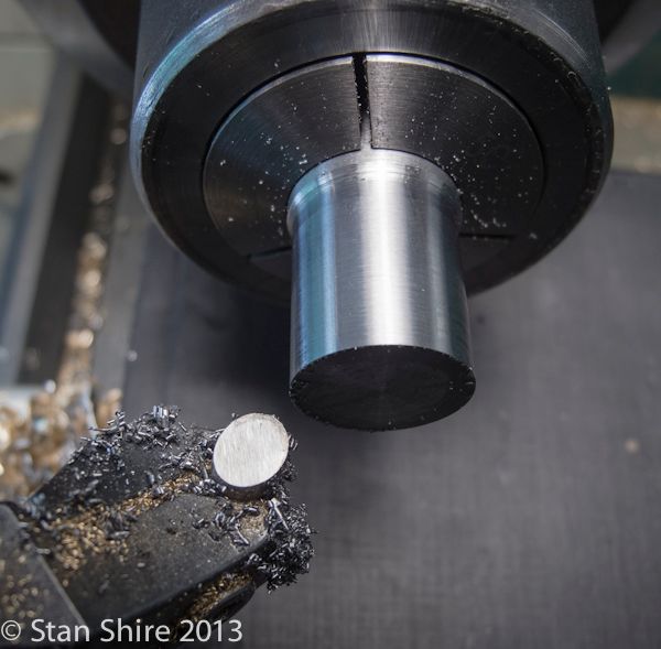
Here's the drawing and the piece of 12L14 steel that is big enough for the two eccentrics.
Into the 5C collet and turn to the correct diameter with my go-to, round HSS bit in the tangential toolholder. I've got the SFM display on the lathe showing 180 (that's for you feeds n' speeds guys) The finish is right off the tool. ScotchBrite? I don't need no stinkin' Scotchbrite!
Moving the collet to a block and centered at the mill.
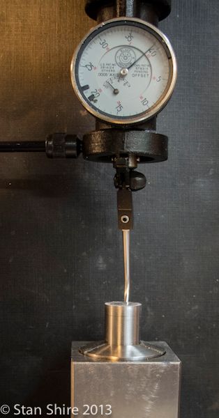
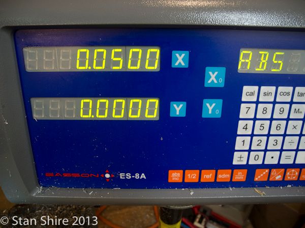
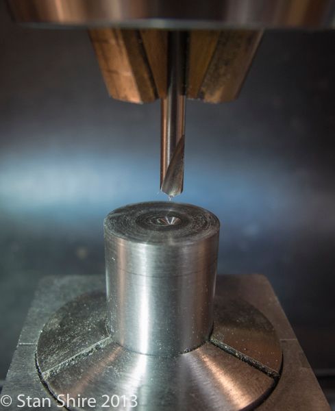
Elmer's plans show a 0.05" offset for the eccentric. Dialed that in on the DRO and then center drilled.
I cleaned up the face a bit and then back to the lathe with the Keats Angle plate on the spindle.
I mounted the part in the V and then loosened both SHCS holding the Keats to the faceplate.
Bringing a tailstock center up to the center drilled spot and apply enough pressure with the tailstock to hold the Keats to the faceplate while I tightened the SHCS's.
Is this as accurate as a 4-jaw and an indicator. Not! But, the eccentrics on the engines where I've used this technique run just fine. If I were a real machinist, I'd probably get fired.
This is quick and seems to work just fine.
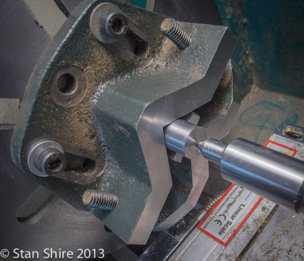
Now, just keep doing that interrupted cut until it smooths out and the eccentric diameter is correct.
The test fit with the eccentric strap.

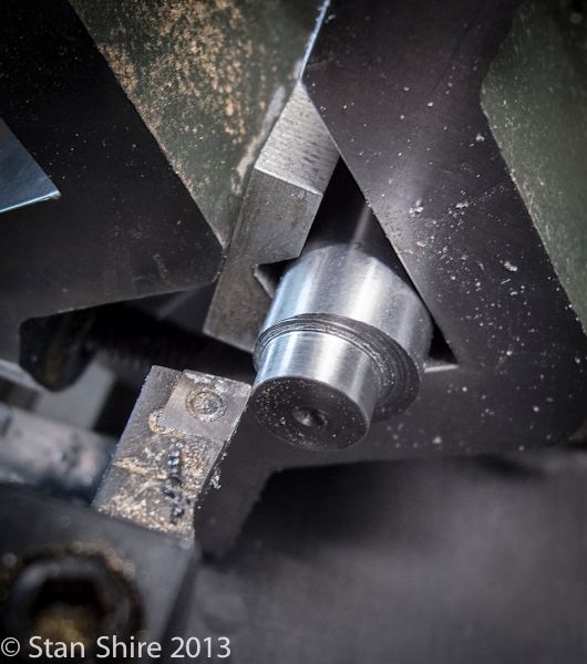
My intent was to flip the piece around and turn the eccentric on the opposite end. The piece was a bit too short to keep the Keats jaw parallel and bear evenly on the piece. Now, here's why I like the Keats .
I unthreaded the faceplate from the lathe spindle, put the 5C chuck on and turned a spacer block to give even bearing on the jaws. Replaced the 5C with the Keats, put the part and the spacer in, tightened up the V jaw and turned the second eccentric.
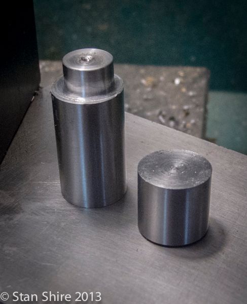
Back to the 5C chuck for parting off.

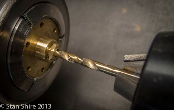
Since the part is already centered in the 5C, I drilled and reamed for the shaft.
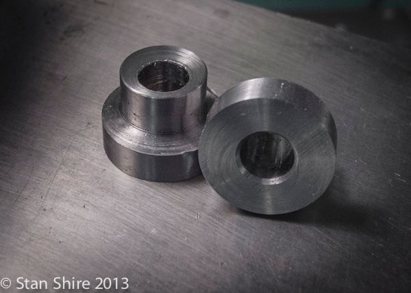
Two more parts. There are some cranks, rods, etc coming, but I think I want to move on to the pumps next.
Yes, you're right. I could have done the eccentric in the 4-jaw, but I thought I'd show another way without using an indicator OR a 4-jaw.
Machining the eccentric in the Keats Angle Plate has the advantage of being able to remove the part for another operation and then return it without indicating again. Also, multiple parts (as in two eccentrics) work just fine.
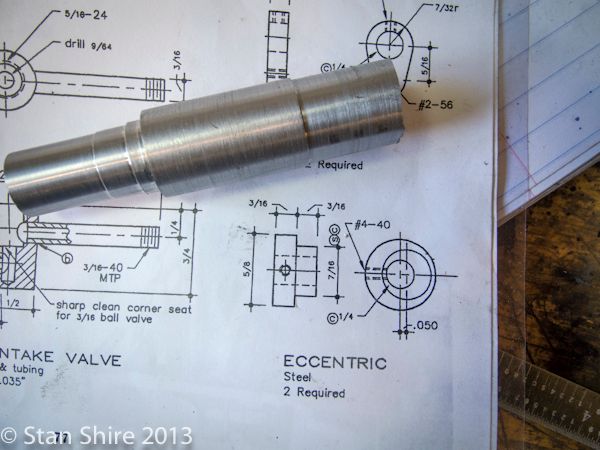
Here's the drawing and the piece of 12L14 steel that is big enough for the two eccentrics.

Into the 5C collet and turn to the correct diameter with my go-to, round HSS bit in the tangential toolholder. I've got the SFM display on the lathe showing 180 (that's for you feeds n' speeds guys) The finish is right off the tool. ScotchBrite? I don't need no stinkin' Scotchbrite!

Moving the collet to a block and centered at the mill.

Elmer's plans show a 0.05" offset for the eccentric. Dialed that in on the DRO and then center drilled.


I cleaned up the face a bit and then back to the lathe with the Keats Angle plate on the spindle.
I mounted the part in the V and then loosened both SHCS holding the Keats to the faceplate.
Bringing a tailstock center up to the center drilled spot and apply enough pressure with the tailstock to hold the Keats to the faceplate while I tightened the SHCS's.
Is this as accurate as a 4-jaw and an indicator. Not! But, the eccentrics on the engines where I've used this technique run just fine. If I were a real machinist, I'd probably get fired.
This is quick and seems to work just fine.

Now, just keep doing that interrupted cut until it smooths out and the eccentric diameter is correct.

The test fit with the eccentric strap.

My intent was to flip the piece around and turn the eccentric on the opposite end. The piece was a bit too short to keep the Keats jaw parallel and bear evenly on the piece. Now, here's why I like the Keats .
I unthreaded the faceplate from the lathe spindle, put the 5C chuck on and turned a spacer block to give even bearing on the jaws. Replaced the 5C with the Keats, put the part and the spacer in, tightened up the V jaw and turned the second eccentric.

Back to the 5C chuck for parting off.

Since the part is already centered in the 5C, I drilled and reamed for the shaft.

Two more parts. There are some cranks, rods, etc coming, but I think I want to move on to the pumps next.

Sshire
Well-Known Member
- Joined
- Jun 29, 2011
- Messages
- 936
- Reaction score
- 259
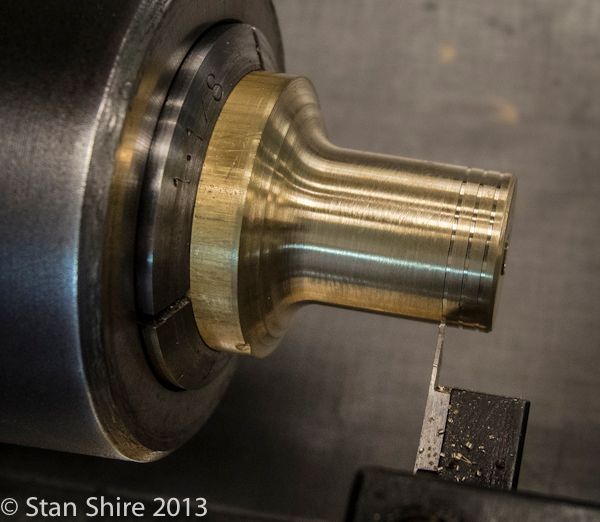
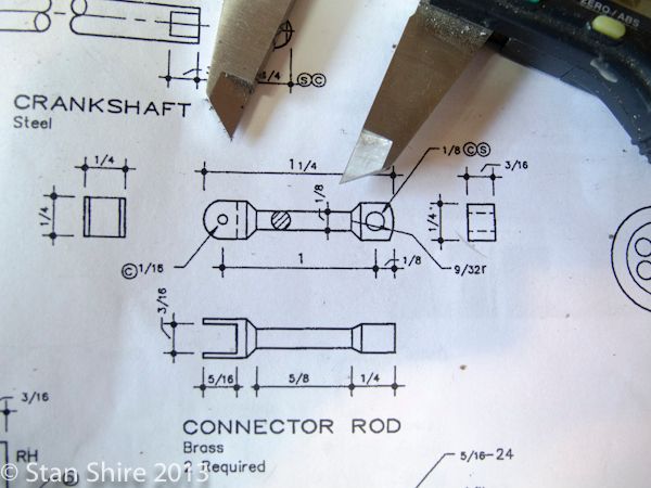
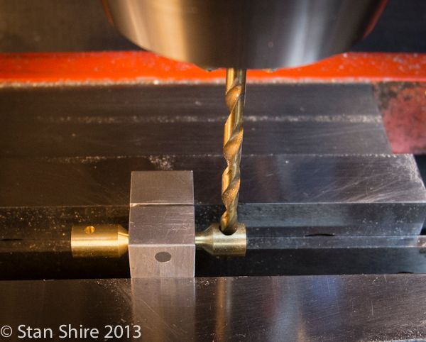
Connecting Rod
The connecting rods have holes for pins. At 90 degrees to these holes, one end has a slot and the other end a flat.
I've done these kinds of rods on other engines, but was thinking about a different way to approach the problem. I enjoy the problem solving almost as much as the actual machining. so here's my "new" solution.
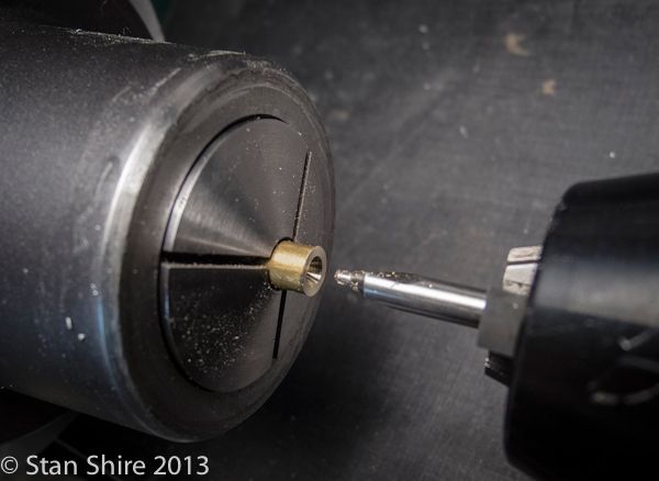
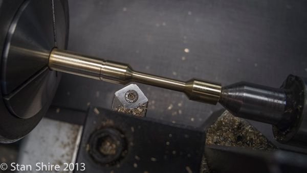
Since the rods are .25 in diameter and there would be about 1.5" hanging out of the collet, the import (from the U.K) thin live center seemed perfect for this. (Thanks for mentioning that one Bogs) With the .25 brass rod just a bit out of the collet, I center drilled.
Per Elmer's drawing, I marked the points for turning the rod.
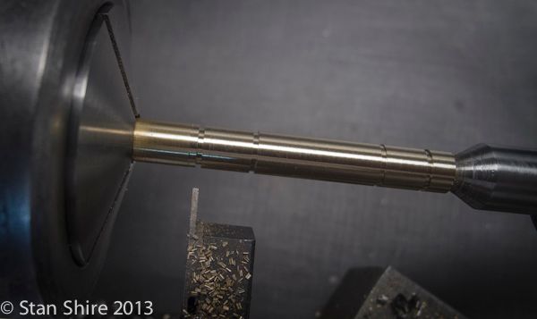
This HSS tool allowed me to cut left and right and have the bevel at the ends. I made one pass and the miked the diameter. Set this diameter as X on the DRO and then turned until the DRO displayed .125. Parted off and done.
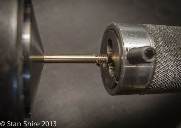
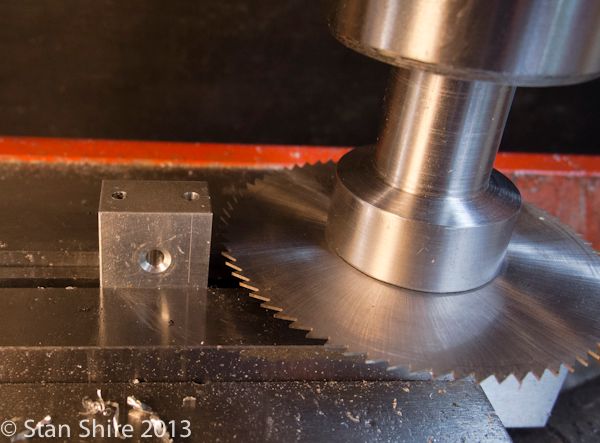
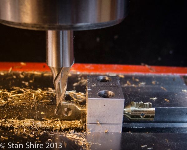
To deal with the 90 degree, self-induced, problem, I squared a small aluminum block in the mill, drilled and tapped two holes to hold the fixture together, reamed a .126 hole through the center and then split it with a .02 saw.
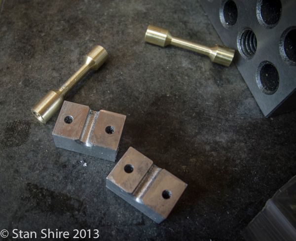
Now we have this.
And when assembled, the rods are trapped in the block.
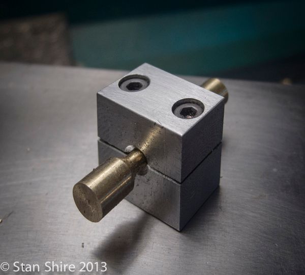
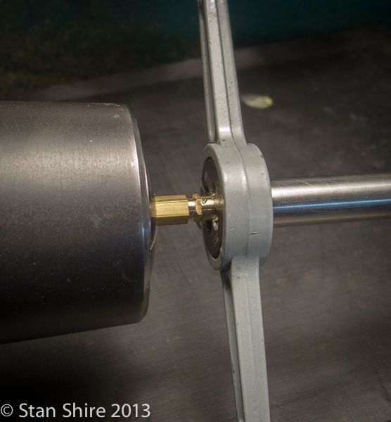
Now when the block is in the vise for drilling, It can be revolved to the next face for milling the slot and the flat faces at 90 degrees.
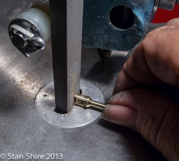
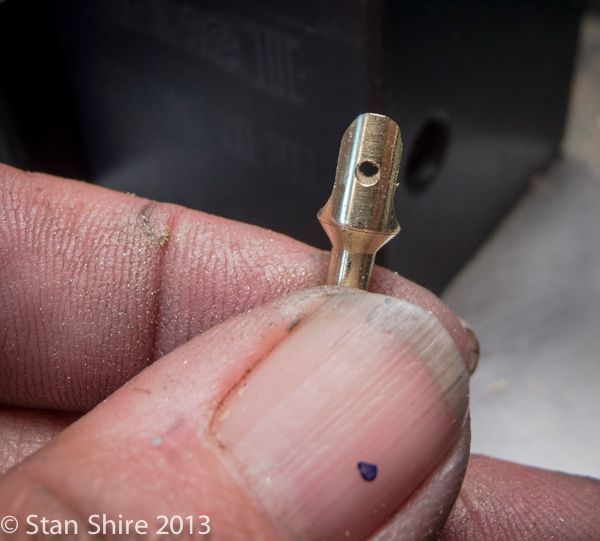
A visit to Oliver to round the end and I'm happy with the two connecting rods.
The connecting rods have holes for pins. At 90 degrees to these holes, one end has a slot and the other end a flat.

I've done these kinds of rods on other engines, but was thinking about a different way to approach the problem. I enjoy the problem solving almost as much as the actual machining. so here's my "new" solution.
Since the rods are .25 in diameter and there would be about 1.5" hanging out of the collet, the import (from the U.K) thin live center seemed perfect for this. (Thanks for mentioning that one Bogs) With the .25 brass rod just a bit out of the collet, I center drilled.

Per Elmer's drawing, I marked the points for turning the rod.

This HSS tool allowed me to cut left and right and have the bevel at the ends. I made one pass and the miked the diameter. Set this diameter as X on the DRO and then turned until the DRO displayed .125. Parted off and done.

To deal with the 90 degree, self-induced, problem, I squared a small aluminum block in the mill, drilled and tapped two holes to hold the fixture together, reamed a .126 hole through the center and then split it with a .02 saw.

Now we have this.

And when assembled, the rods are trapped in the block.

Now when the block is in the vise for drilling, It can be revolved to the next face for milling the slot and the flat faces at 90 degrees.


A visit to Oliver to round the end and I'm happy with the two connecting rods.


Sshire
Well-Known Member
- Joined
- Jun 29, 2011
- Messages
- 936
- Reaction score
- 259
Marv and Bogs' Great Flywheel Adventure
My first engine, made when I only had a mill, was a Stan Bray wobbler. The flywheel was a .25" wide brass disk with holes drilled through.
Then next flywheels were aluminum with a shallow center recess and finally, built up flywheels with inserted spokes.
I realized that, while I could do another built up flywheel, It was probably time to learn how to make a one-piece spoked flywheel from bar stock.
I read and re-read John Moore's (Bogstandard) exceptional treatise on Soft Jaws and Flywheels many times. If you haven't read that one, you really must. It has an incredible amount of information. Why is it taking so long for the Queen to knight him?
I also had read many posts about how essential Marv Klotz's Flywheel Program is if you are doing spoked flywheels. Since I don't have a Windows computer, but my MacBook Pro can natively run Windows, I downloaded Flywheel, entered the appropriate numbers and printed the output file.
Jeez, Marv. That M.I.T. education was worth every penny. I did a test with a 6061 blank and a Sharpie chucked in a .500 R8 collet (highly recommended). Bang on perfect!
So step one of the Great Flywheel Adventure was to cut a chunk from a 3" bar of cast iron.
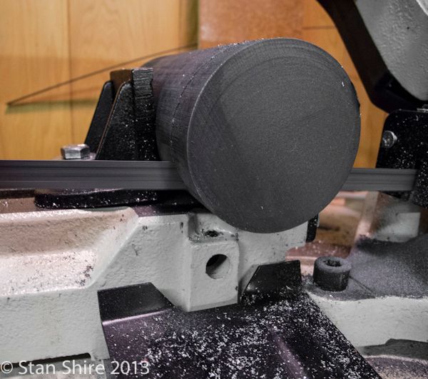
With the three-jaw on the spindle, I bored the soft jaws to just fit the C.I. blank. Faced one side and most of the edge, flipped it over and repeated.
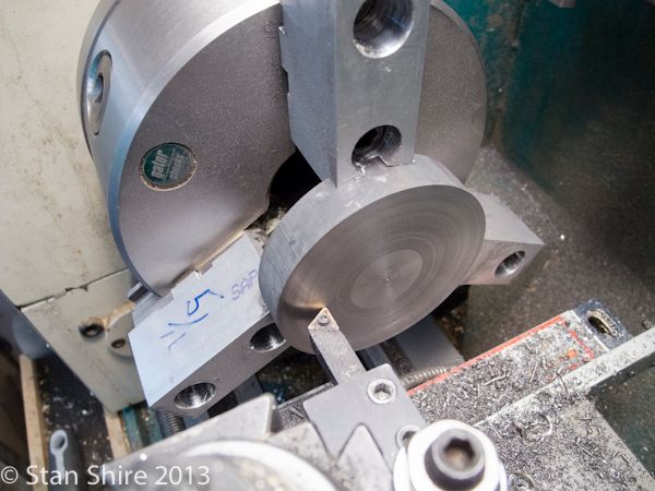
Then drilled and reamed a .126 center hole.
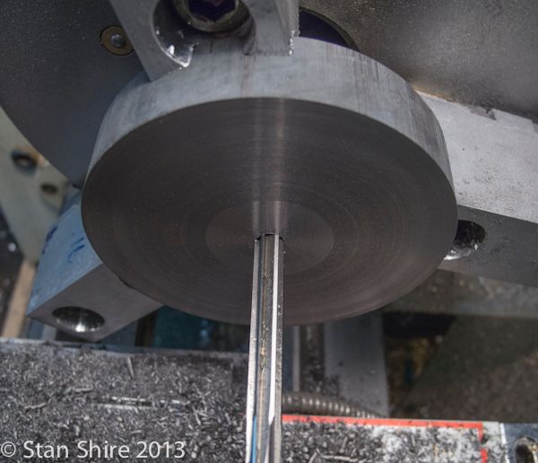
The only other time I had machined cast iron, was the backplate for the three-jaw chuck. That was mostly complete as I received it, just needing a few thou off to make a good fit. This was a whole other story. My usual procedure in recessing a flywheel is to use the HSS trepanning bit that was ground according to another of Bogs' posts (the man never quits.) Obviously (now it's obvious) the C.I. ground the trepanning cutter better than my bench grinder.
So with an assortment of carbide boring bars, left and right hand insert tools and anything else that would work, I managed to recess both sides of the flywheel.
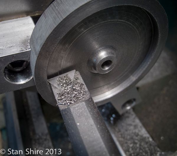
With that exercise taking most of the day, I was not about to put the "good" flywheel blank through the Klotz Maneuver without a test to "refine" my procedure and to make sure I understood it all.
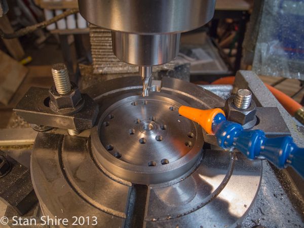
I cut a 3" piece of 6061 to the same thickness as the flywheel (0.50"), put it in the soft jaws and drilled the 0.25" center hole. I did not recess it as my trepanning tool is in need of major regrinding after its meeting with Mr. Cast Iron.
With this mounted on the R.T., I chucked the aforementioned Sharpie in the mill and followed the output of Marv's Flywheel program.
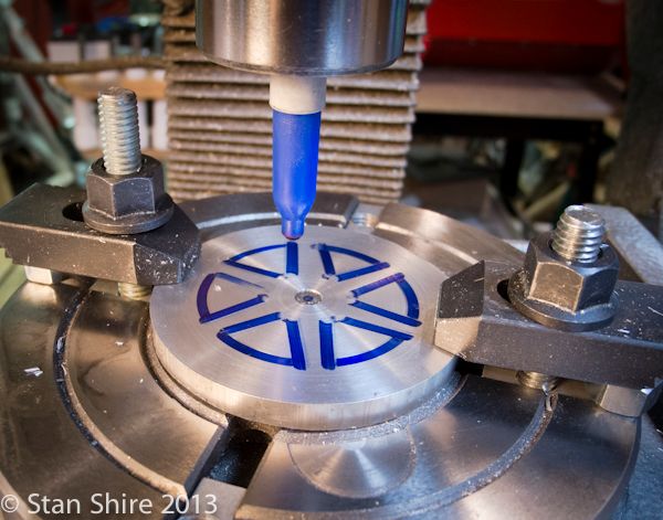
That went well, so I replaced the Sharpie with actual cutters and proceeded to do the whole thing again. Excellent practice for the real thing.
My R.T. will accept a MT2 center. I've drilled and tapped it ¼-20 so I can make close fitting centering posts.
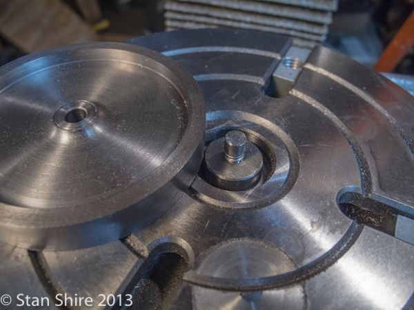
Ready to start. The part is clamped to the R.T. and Marv's instructions are close at hand.
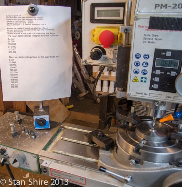
Much handle cranking and paying very close attention. Double and triple checking before each cut. Phone ringer turned off.
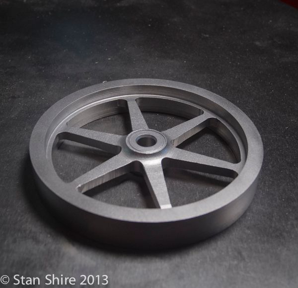
Almost completed with no mistakes on my part. Must be a first.
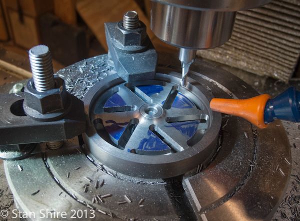
John did mention filing. Some quality time with Oliver here. The round edge file is a perfect match for the corner radii.
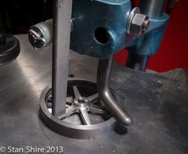
My plan is to paint the flywheel and then sand the side flats and rim to a shiny finish. When painting my built up, spoked flywheels, I've had good results with bead blasting and etching primer.
I still have a few spots that need attention but I wanted to see how the C.I. looks after a trip to the blast cabinet with glass beads.
Hoping to get to the bearing supports and bearings tomorrow so I can see how this flywheel looks (and turns) in place.
My first engine, made when I only had a mill, was a Stan Bray wobbler. The flywheel was a .25" wide brass disk with holes drilled through.
Then next flywheels were aluminum with a shallow center recess and finally, built up flywheels with inserted spokes.
I realized that, while I could do another built up flywheel, It was probably time to learn how to make a one-piece spoked flywheel from bar stock.
I read and re-read John Moore's (Bogstandard) exceptional treatise on Soft Jaws and Flywheels many times. If you haven't read that one, you really must. It has an incredible amount of information. Why is it taking so long for the Queen to knight him?
I also had read many posts about how essential Marv Klotz's Flywheel Program is if you are doing spoked flywheels. Since I don't have a Windows computer, but my MacBook Pro can natively run Windows, I downloaded Flywheel, entered the appropriate numbers and printed the output file.
Jeez, Marv. That M.I.T. education was worth every penny. I did a test with a 6061 blank and a Sharpie chucked in a .500 R8 collet (highly recommended). Bang on perfect!
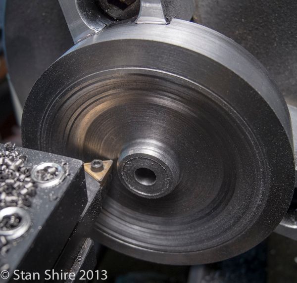
So step one of the Great Flywheel Adventure was to cut a chunk from a 3" bar of cast iron.

With the three-jaw on the spindle, I bored the soft jaws to just fit the C.I. blank. Faced one side and most of the edge, flipped it over and repeated.

Then drilled and reamed a .126 center hole.

The only other time I had machined cast iron, was the backplate for the three-jaw chuck. That was mostly complete as I received it, just needing a few thou off to make a good fit. This was a whole other story. My usual procedure in recessing a flywheel is to use the HSS trepanning bit that was ground according to another of Bogs' posts (the man never quits.) Obviously (now it's obvious) the C.I. ground the trepanning cutter better than my bench grinder.
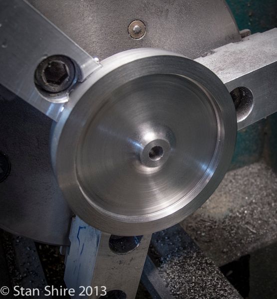
So with an assortment of carbide boring bars, left and right hand insert tools and anything else that would work, I managed to recess both sides of the flywheel.


With that exercise taking most of the day, I was not about to put the "good" flywheel blank through the Klotz Maneuver without a test to "refine" my procedure and to make sure I understood it all.
I cut a 3" piece of 6061 to the same thickness as the flywheel (0.50"), put it in the soft jaws and drilled the 0.25" center hole. I did not recess it as my trepanning tool is in need of major regrinding after its meeting with Mr. Cast Iron.
With this mounted on the R.T., I chucked the aforementioned Sharpie in the mill and followed the output of Marv's Flywheel program.

That went well, so I replaced the Sharpie with actual cutters and proceeded to do the whole thing again. Excellent practice for the real thing.

My R.T. will accept a MT2 center. I've drilled and tapped it ¼-20 so I can make close fitting centering posts.

Ready to start. The part is clamped to the R.T. and Marv's instructions are close at hand.

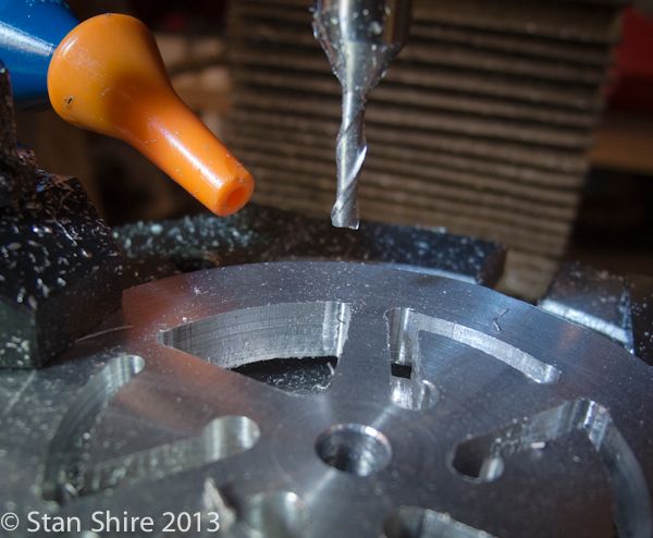
Much handle cranking and paying very close attention. Double and triple checking before each cut. Phone ringer turned off.

Almost completed with no mistakes on my part. Must be a first.

John did mention filing. Some quality time with Oliver here. The round edge file is a perfect match for the corner radii.

My plan is to paint the flywheel and then sand the side flats and rim to a shiny finish. When painting my built up, spoked flywheels, I've had good results with bead blasting and etching primer.
I still have a few spots that need attention but I wanted to see how the C.I. looks after a trip to the blast cabinet with glass beads.

Hoping to get to the bearing supports and bearings tomorrow so I can see how this flywheel looks (and turns) in place.
Similar threads
- Replies
- 19
- Views
- 2K
- Replies
- 111
- Views
- 21K