Elmer's Pumping Engine

Home Model Engine Machinist Forum

Help Support Home Model Engine Machinist Forum:

This site may earn a commission from merchant affiliate links, including eBay, Amazon, and others.

Sshire

Well-Known Member
Joined
Jun 29, 2011
Messages
936
Reaction score
259
Elmer's pumping engine

Since I've been home from Cabin Fever for a few days, it's time to begin making engines for next year.

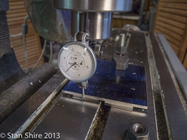
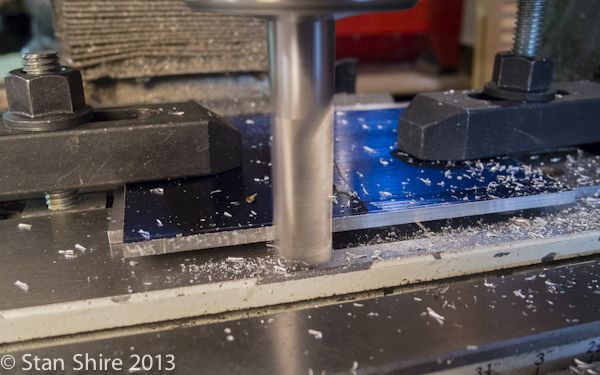
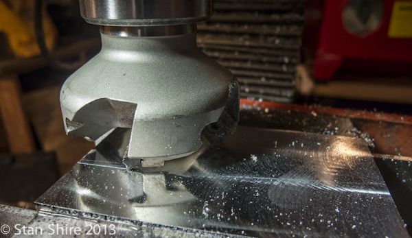
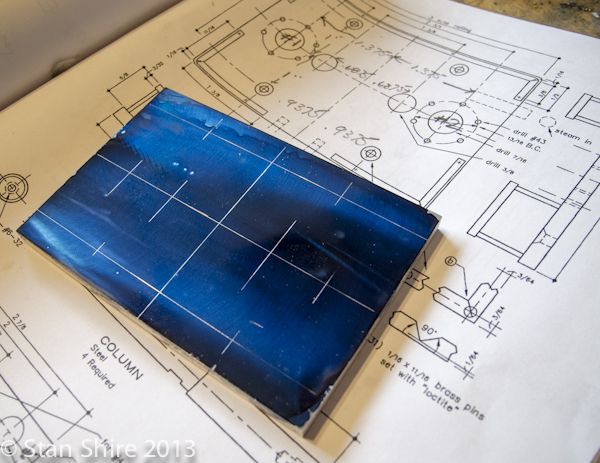
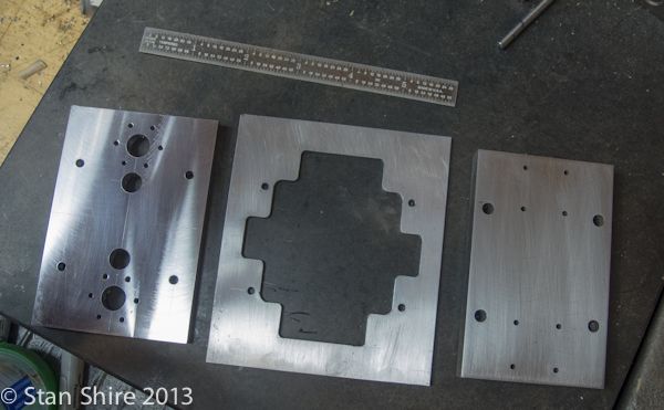
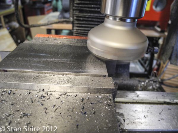
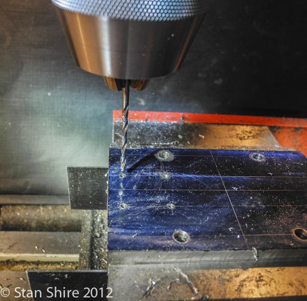
The first will be Elmer's Pumping Engine. As usual for me, I'm working bottom up. I had a piece of 1/2" 12L14 that will be good for the base. After squaring it up and milling to size, I flattened it with the face mill.

ElmersPumpingEngine-1.jpg


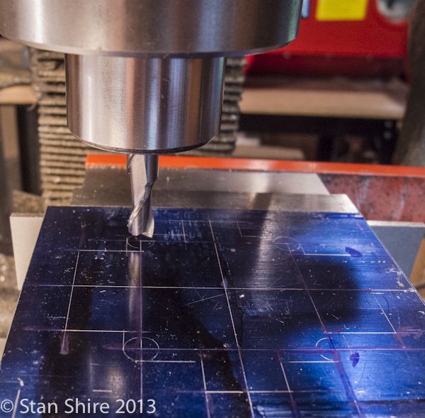
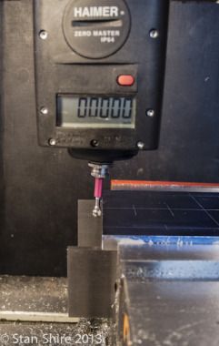
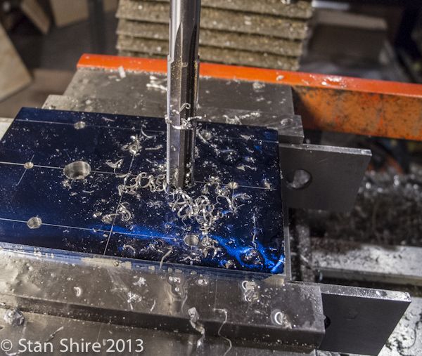
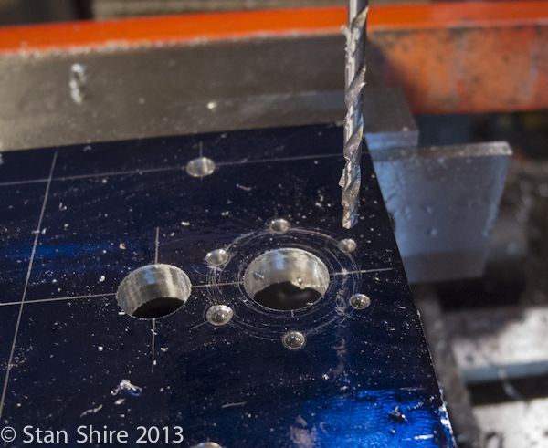
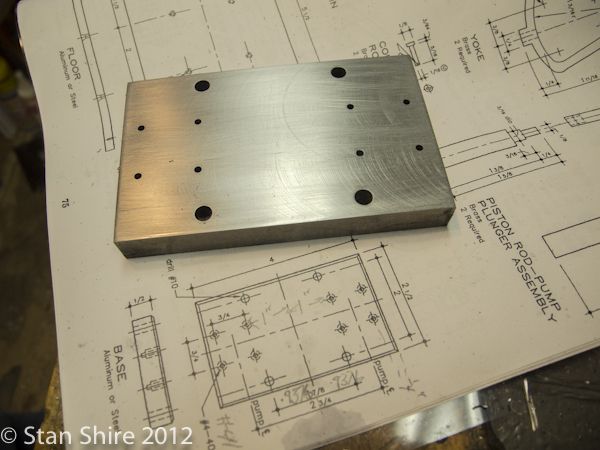
Even though all holes will be positioned with the DRO, I marked out all of the spots for drilling. This is just to prevent brain drift or reading a number incorrectly.*

ElmersPumpingEngine-2.jpg


Not much interesting or revolutionary here, but part one is done.

ElmersPumpingEngine-3.jpg


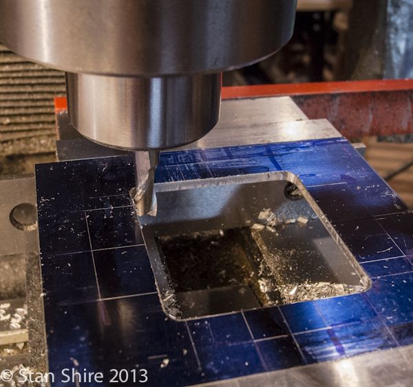
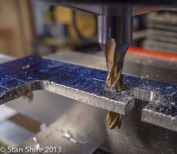
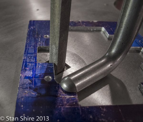
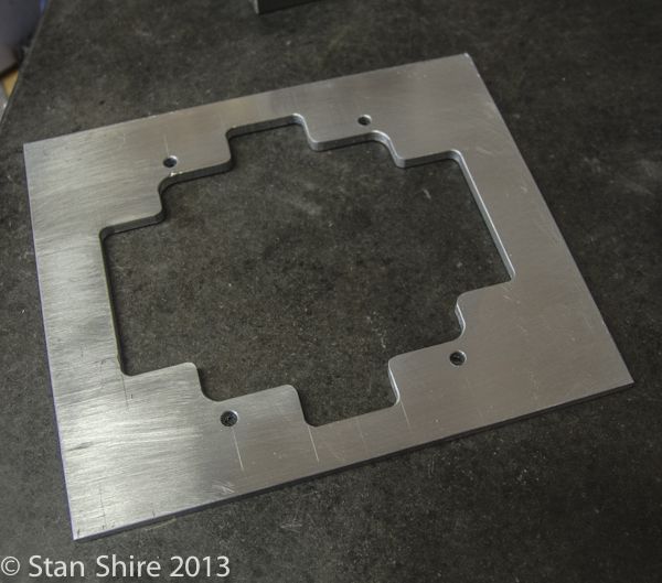
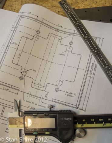
Next will be the catwalk. This should be much more interesting once I decide how I'm going to do the center opening. (drill corners and saw to connect or center cutting end mill and just DRO around the perimeter until the middle piece of aluminum falls out.)

ElmersPumpingEngine-4.jpg
 
Elmer's pumping engine 2

The piece for the catwalk was too wide for the vise to mill the edge. My first try was to stand it up in the vise, but it was too thin and chattered. I elevated it on pair of parallels and clamped it to the table after getting the reference edge perfectly aligned (for me, half a thou over the whole edge is perfect enough.)

ElmersPumpingEngine-5.jpg


I got a nice clean cut. No chatter.

ElmersPumpingEngine-6.jpg


Here's the catwalk plate marked out. Even though I'm using the DRO, this is a good check to make sure I'm not doing something I'll later regret. (My stupid preventer)

ElmersPumpingEngine-7.jpg


Plunged in the end mill and DRO'd my way around the inner part of the opening.

ElmersPumpingEngine-8.jpg


Switching to a smaller end mill and cutting the outer openings. DRO from A to B to C.

ElmersPumpingEngine-9.jpg


First time actually using the Oliver Die Filer that I got at Cabin Fever on an engine It seems perfect to round the outer corners. I love the slow speed of the Oliver. Much more control for the filing-challenged. I got the three files (triangle, lozenge and crochet) from Victor in Brooklyn yesterday. Very nice. Can't wait to use those.

ElmersPumpingEngine-10.jpg


The completed catwalk. The Oliver rounded corners look reasonably similar to one another. I'm happy.

ElmersPumpingEngine-11.jpg


On to the engine's table. A quick cleanup with the facemill.

ElmersPumpingEngine-12.jpg


The table marked out.

ElmersPumpingEngine-13.jpg


I know the Haimer is probably overkill for edge finding but it works wonderfully and is dead on accurate. No more multiple checks with the Starrett.

ElmersPumpingEngine-14.jpg


Just lots of spot drilling, hole making and reaming.

ElmersPumpingEngine-15.jpg


And bolt hole circles with the DRO.*

ElmersPumpingEngine-16.jpg


Three horizontal pieces done.

ElmersPumpingEngine-17.jpg
 
Stan - its looking good!

I was about to start this one, but decided to build the 3 cylinder radial first - the Pumping Engine will be next. It looks like it should deliver about 7 times the volume of the Vauxhall Donkey Pump.

I'll follow your build with interest - I've seen a couple of examples of this engine finished, but never a build log.

Kind regards

Geoff at Inky Engines
 
This looks really great. How do you use the DRO for the holes?? I have one , but not ready installed.
 
Using the D.R.O. for holes is easy and much more precise than marking out.
You use an edge finder to set the D.R.O. to zero on an edge and just move over to the dimension you want then drill.
Round hole patterns are available on most D.R.O.'s-you enter the number of holes and the radius an it will promt you to go to zero for each hole in the pattern.
I use a D.R.O. at work and I recently installed one on my mill-drill-now it works almost as well as a bridgeport mill.
cheepo45
 
The built in functions on the DRO (not to be confused with the digital caliper style with remote display) are extremely useful. In addition to the bolt hole circle that Cheepo45 described, the one that I use the most is the SDM (sub datum memory). Not sure what that means but it can remember hundreds of points. Let's say you need to spot drill, drill and tap 10 holes. You either do each one to completion - spot drill, change to drill bit, drill hole, change to tap and tap the hole. Now repeat this 9 more times. That's about 30 or so tool changes.
The way I do it with SDM is spot drill, add that location as SDM #1. Move to next location, spot drill and add as SDM #2, etc.
When all 10 are spot drilled, change to the drill bit. Display SDM # 1 and move the table to x and y at 0 on the display. Drill the hole Down arrow to display SDM #2. Go to x0 and y0 and drill. Etc.
Then repeat with the tap..
3 tool changes.
Another function thats nice is center-find. Edge find on one edge and zero that axis.. Edge find the opposite edge. Press the 1/2 button and the center of the part is now set as zero on the display.
 
I had expected to turn the 4 columns for Elmer's pumping engine today. Set up a 3/8" brass round in a 5C collet, end drilled for the live center, touched off the cutter, turned the knob for my independent carriage feed and the carriage didn't move. The motor for the carriage had no power. I checked all of the usual suspects; breaker to the motor's power supply, switches, plugs. Nothing wrong there. Time to get out the multimeter for in depth troubleshooting and the batteries in the multimeter were dead.*
In the car to the drugstore (they seem to have fewer drugs and more junk) to the button battery rack. Out of what I needed. On to the next drugstore. Success.*
Back home with fresh batteries in the multimeter. Power in is fine. 120 VAC. Power out is not 12 VDC. It's 0 VDC.*

Open up the power supply. Aha. Blown fuse on the circuit board. Of course I had every fuse but the correct one.*
Back in the car and off to Radio Shack. They actually had the needed fuse. 5 pack on hand and back home. Unsolder blown fuse. Solder in new fuse. Plug in power supply. Flash! Pop! Fuse blew. Careful inspection of components on the circuit board gave me no useful information. No loose electrons dashing madly about.*
Order new power supply from Amazon.*
Yes, I could reconnect the gears in the lathe for the carriage feed but even the slowest gearing is too fast for the finish that I want.*
Power supply will arrive on Tuesday.
The Pumping Engine's columns await.*
 
Back in business! The power supply for my independent carriage feed passed away and the new one arrived a few days ago. It's now connected and all is well.
I had few hours today and turned the columns ( no pictures of the column turning. You've seen 3/8" brass turned before.)

ElmersPumpingEngine-18.jpg


I like the way they look but may flute the lower parts.

Assembled the "frame" just to make sure everything fit correctly.

ElmersPumpingEngine-19.jpg


I'm going to look at the drawings this evening and plan my weekend in the shop. Not sure if I'm going to work bottom to top (pumps then cylinder, piston, steam chest, etc.) or top to bottom.*
The fun continues.
 
Stan. Looks like you are getting some use with that new toy. Looks great

Dave
 
I have so got tool envy right now. Oh do I want one of those die filers...

Where'd you say you live? :p
 
Cylinder Saturday
Deciding to work top-down, (although that could change at any time) the steam cylinders were the next culprit.
I've made five of Elmer's engines and this one, without a doubt, has the most error-laden set of drawings yet. Either Mr. Verburg was in a hurry ("Elmer, will you get out of the damn shop. Dinner's getting cold") or he was thinking about the next one. (Hey! I wonder if I could make an external gear run around an internal gear?") *I've been really careful after I realized this and look at the part and any others that have any relation to it. He suggests drilling the cylinder ports before boring the "½ hole through the cylinder." The drawings specify a 5/8" cylinder, piston and heads. I'm pretty sure he knew that a 5/8" piston just isn't going to fit in a ½" bore. Just a caution if this is on your build list. On to today's parts.

Two pieces of 360 brass from the brass box. They need to be 1" cubes.


So face mill all sides until they're 1" cubes. One is actually a 1.002 cube and the other is 1.003 but that close enough. I figure that by the time I get them smooth and shiny with no tool marks, they should be there.


After centering a block in the vise, Spot drilled and drilled three intake ports. (Elmer sez "drill 9 holes" which is correct for the valve plate but not the cylinder.)


The exhaust ports are done with a 1/16" end mill. The finished depth is .125. I have broken one of these on another engine, so my procedure is 4 passes at about .030 depth each; high spindle speed and VERY slow feed. Worked perfectly. Two ports done.
If it's not obvious, I'm doing both cylinders. No sense repeating a setup.


Ports completed. Now onto the passage to connect the ports to the cylinder.


The passage is at an 11 degree angle. Elmer is right on that one. It's fairly important here to have the setup accurate as the passage needs to meet the 1/16" ports on the face. Time for the sine vise.
I can get the sine of 11 degrees just fine; I know that my vise is 4" long. I can multiply the sine of 11 degrees times 4, but as soon as I open this, I turn into a drooling, Johansson-challanged idiot. I've read the procedure; start at the right end of the number and work left. All that is behind me now. 99 cent iPhone app. Tell it how many blocks are in your set, what stack height you need. Magic! A list of the needed blocks is right there.


.125 end mill first to keep the drill from skating off target.


Then the 1/16" drill and , AMAZING!, the passage ends up dead center in the port.


Cylinder bore comes next. I gathered up an ascending size group of bits and a 5/8" reamer and made a hole.


Two cylinders nearing completion here.


Just put them where they will eventually end up. I'm pretty much done for the day here. Tomorrow I hope to get the 24 bolt holes (2-56 thread) finished. They're for the heads.


Thanks for watching.
 
Nice work, Stan. Your pictures and documentation are excellent.
cheepo45
 
Stan, looks great!!! Keep it up

Dave
 
Thanks guys. One part at a time. I need fresh stock for Cabin Fever 2014
 
Twenty-Four Holes
My plan for today was to drill and tap both steam cylinders (2-56 blind holes) and to make the steam chest valve plates and covers. (It also included the two steam chests but that didn't happen).

With two steam cylinders; 6 bolt holes at each end, I had 24, 2-56 holes to tap. I pulled the little-used Tapmatic tapping head out and re-read the instructions (which are minimal help.)
I tried a few test holes and got the details sorted out (set quill stop on the mill, Tapmagic handy, breath held and cheeks clenched)

Center the bore with one of my best Ebay scores: the Blake Co-Ax indicator. I also put a small vise stop to the right of the cylinder to locate it when I turn it upside down to drill and tap the holes at the other end.


With the DRO handling the Bolt Hole Circle calculations, I just followed along. Spot drill all holes, change to the drill bit and drill all holes, tap all holes. Flip the cylinder over. Rinse and repeat.


I use form taps with the tapping head. They use a different tap drill size but instead of cutting the metal and creating chips, the actually press into the metal with no chips. They also seem quite resistant to breaking even with the 2-56. When I changed from spiral flute and spiral point taps for the Tapmatic, I didn't even consider "import" form taps. USA made Balax. The tech support people couldn't have cared less that my total order from Enco was three taps. They spent a long time on the phone discussing what I was tapping, what alloys, what size mill, etc. They sent me tap drill size charts. Gotta love support like that.


The cylinder was flipped and the process repeated. I indicated the second cylinder and with no issues at all, both are done.


The Steam Chest valve plates and cover plates are .065 brass. I cut four pieces and, since they are the same size, milled all four to size in one shot.


I put the first one in the vise and set the DRO memory for all 13 holes (the covers have 4 holes, but the valve plate has those same four plus nine really tiny holes at the center. A number 57 drill bit.
Drilled the corners on all four (#47 IIRC) and then moved on to the #57 holes. I knew things were going too well.


Success! No parts were harmed in the extraction of the broken bit.


Not having another #57 bit, I was going to move to a #58. I thought that, because I'm just naturally curious, I would have a go at sharpening the #57 as most of it was still there. I approached this very scientifically. Pushed the belt straight into the 1" belt sander then turned the bit at what look like an angle that might be a drill bit. rotated it in my fingers about half way around and repeated the very precise angle. With a small scrap of brass in the vise I gave it a try.
I cut way better than it did before it snapped. Huh!


So, a few more parts completed. The Steam Chest is next on the agenda. BTW, I know one of the plates is missing its corner holes (actually I didn't know until I looked at the pictures. Fortunately the hole positions were still in the DRO and I hadn't removed the vise stop)


Thanks for tuning in.
 
I've gotten some time to work on the steam chests. I got a bit sidetracked making table inserts for Oliver (my die filer; an Oliver S-4). I'm trying to make fairly close fitting openings for the various file shapes I've collected as I'd like support as close to the files as possible. In addition, I noticed that the moveable lower clamping jaw was not original. Actually, it is a very bad job. Oliver (the company) was great about sending me a PDF of the drawing for that part. You'll get to see some work with Oliver (the machine) later in this post.

These are the steam chests with a layout just to keep me and the DRO honest.


⅛" end mill. Follow the DRO corner to corner to corner. I'm doing the steam chest a bit differently than Elmer suggests. His method is to clock the part in on the 4-jaw and turn the ends for the valve rod hole and guide. All one piece. Then drill through and tap. My preference is to first mill the opening and then drill and press fit the valve rod hole and valve rod guide as separate pieces.


The orange nozzle is the newly installed air blower. Keeps the work area clear of chips. Quite happy with that. Thanks to Chuck Fellows for making me aware that there was such as thing.

Turning the valve guide piece that will be press fitted. I've done a stepped part rather than Elmer's curves.


I'm trying to do as much finishing on each part as it's done, rather than doing all of the dreaded finishing at the end. Wed/dry up to 2000 grit and then Brasso as a final polish.


The turned valve guides. After drilling holes for them on the mill, these four will be press fitted into the steam chest.


The ratcheting arbor press may be a bit too big for this part but it worked fine.


I seem to have overshot this corner and the press fit insert must be flush. A visit to Oliver is in order.


One of the parallel machine files I got, was a perfect fit for the team chest; flat sides, rounded ends.


A few minutes work yielded this. I'd love to have this shape file in a much finer cut. Oliver (the company) still has files in stock, but basics; square, round and triangular. Also Victornet.
I have gotten some half round files and ground off the teeth at the ends on the belt sander. With the tang cut off, they are clamped "upside down" as the die filer cuts on the down stroke.


Now, drill, ream, tap.


The two fittings for the steam chests threaded and drilled from .250 hex stock. The steam chests are nearing the finish line.


The steam chests completed. A bit more filing, sanding, polishing and these will be ready to go.


I wanted to make sure that all holes in the cylinders, valve plates, valve covers and steam chests lined up. I did a test assembly. All is well.


Next will be the heads, the steam chest valves, the pistons and con rods. The fun never ends.
 
Stan,
Just tuned into this build and I like it. Your photo documentation is superb and is appreciated. I know how difficult it can be to stop in the middle of a cutting operation to take some photos...kudos to you.

Cheers,
Phil
 
The gospel according to Verburg, shows a one piece valve rod. First an .0625 section, followed by a 2-56 threaded section (.25" long) then a 1.25" section and finally a .1875 section with a .0625 slot to accept the eccentric strap. Not being thrilled with all of that rod hanging out of the collet, I decided to make the rod in two parts. My first thought was to silver solder the two pieces together but I was a bit concerned with everything aligning perfectly. So I'm going to thread the two sections and Loctite them.

With the rod in a 5C collet and extending just a bit more than the needed .375", I turned the .09 something rod down to .0625. I like this parting tool for this turning. Very light cuts on each pass and there is less than a thou variation on that section.


Now the rod needs to be extended to turn a longer section for the 2-56 major diameter. Since my super small live center is still way too big, I took a piece of 6061 from the scrap box, and center drilled with a 1/16" bit and put a drop of oil inside. The already turned .0625 section slides in and provides good support.


The 2-56 threaded section is next. Die stock mounted in the tailstock chuck and done.


The right end was next threaded 2-56. 3/16 rod in the collet. Drilled and tapped


Then parted off.


My doctor seems to have an endless supply of these part catchers seen under the piece.

I wanted the end of this piece rounded over. Options were: 1. File to shape 2. Freehand turn 3. Make a form tool 4. Build a ball turner and …………. 5. A corner rounding end mill.

I have no idea where that thought came from, but I first locked a .125 radius tool into a QCTP holder and got it centered and it looked too big.


The .0625 radius seemed right and worked perfectly.


The collet and the part came out of the chuck, went into a square collet block and onto the mill.
The part was centered and very slow passes with a 1/16" end mill made the slot for the eccentric strap without breaking anything.


Since the collet block and part were centered, it was just a matter of tipping the block on its side and drilling the 1/16" hole.


That piece was threaded onto the rod and two more parts are done. Remember, this is a two cylinder engine so nearly everything is times two.

 
Beautiful work Stan. Super pictures tooThm:
There are a few closeups where I believe I can smell the cutting oil;)
Phil
 
Last edited:

Latest posts

Back
Top