Elmer's #33 - a novice makes chips

Home Model Engine Machinist Forum

Help Support Home Model Engine Machinist Forum:

This site may earn a commission from merchant affiliate links, including eBay, Amazon, and others.
Since the valve rod pin is shown above I certainly can't pretend it isn't done and go to bed at a reasonable hour, now can I? Nothing to do but carry on.

The parent stock for the valve rod is still in the three jaw, so let's make the pin from a little further on down the same.
49039-stock.jpg


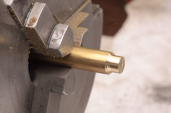
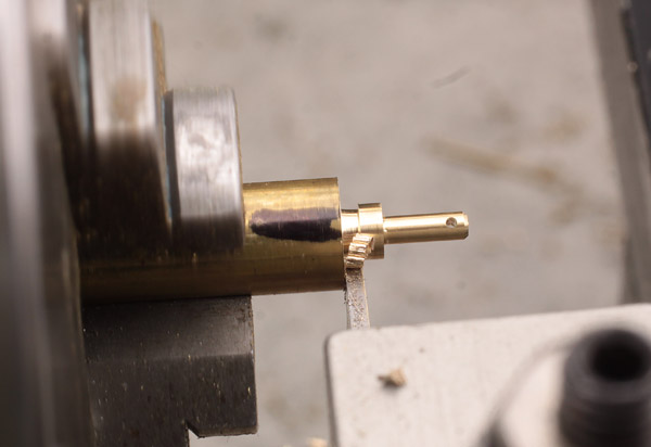
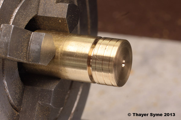
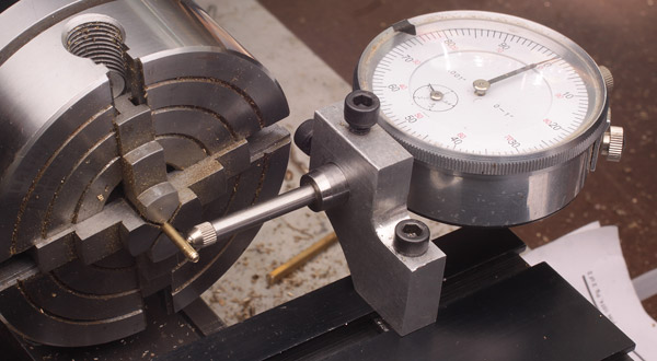
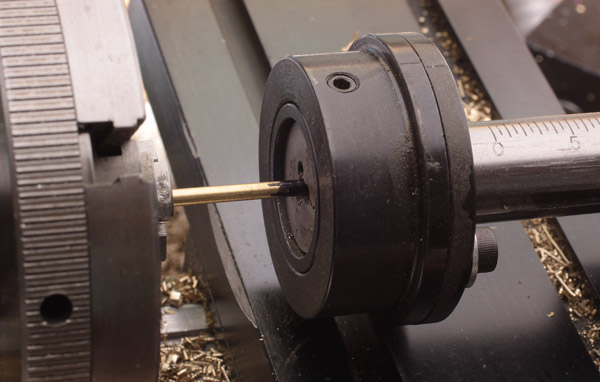
Roughed out to final diameter on the pin and head, left long for parting off and cleaning.
49042-turned.jpg


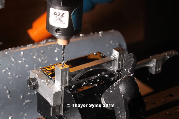
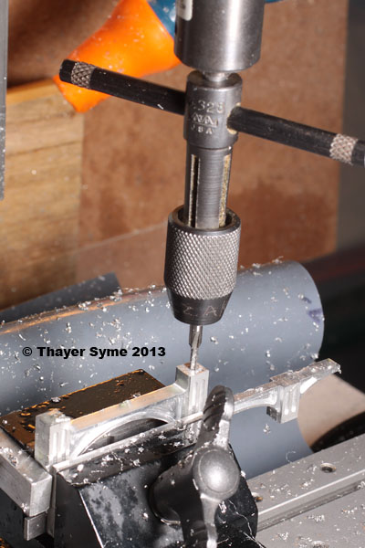
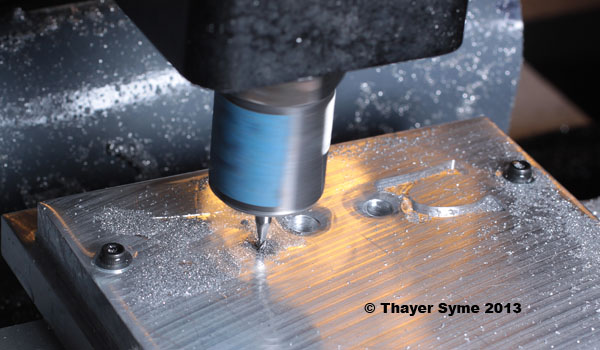
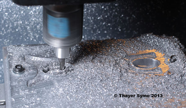
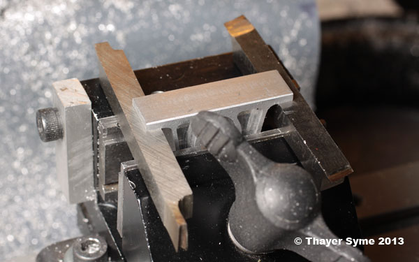
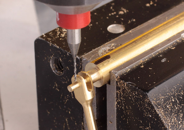
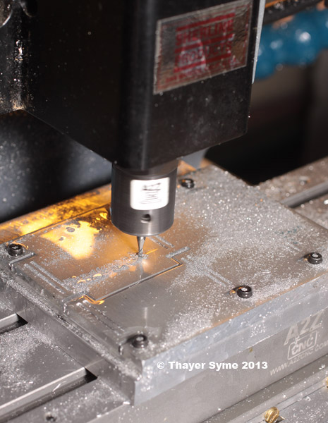
Off to the vise to cross drill. As above, the edge finder, my micrometer and a few buttons on the calculator let me find center on the rod.
49048-edgefinding.jpg


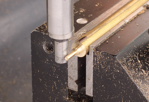
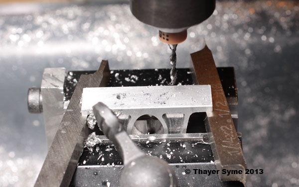
Might as well skip the math and just use the valve rod to ensure adequate clearance on the hole. Elmer calls for a #70 drill here, but the closest I come with the mini carbides is #74 @ .0225. Still plenty of room for a strand of copper wire, so I'm off to the races.
49049-locate-hole.jpg


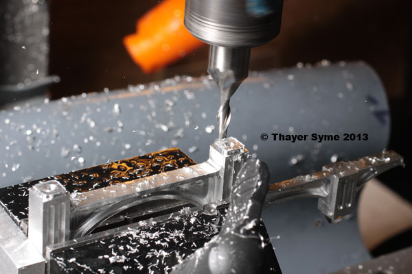
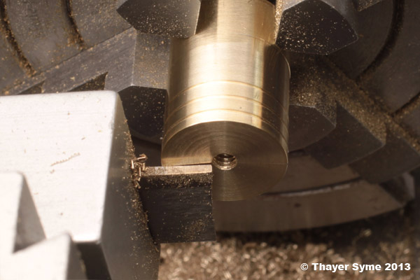
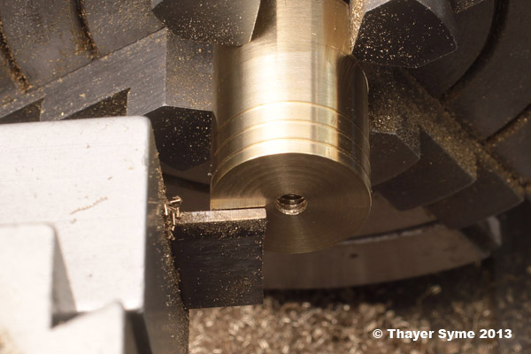
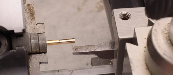
I learned my lesson above and returned it to the 3-jaw after cross drilling. Note the reference Sharpie mark on the stock. It's tougher to see, but there is also one on the jaw face, made at about the same time. That's close enough for parting off.
49061-rechuck.jpg


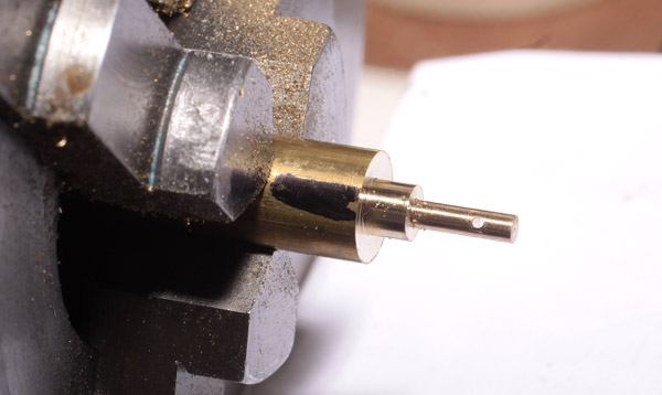
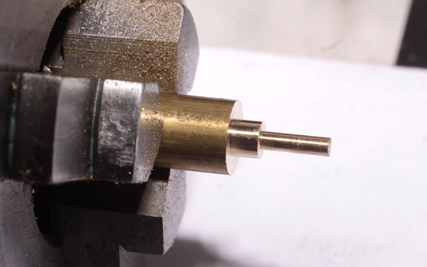
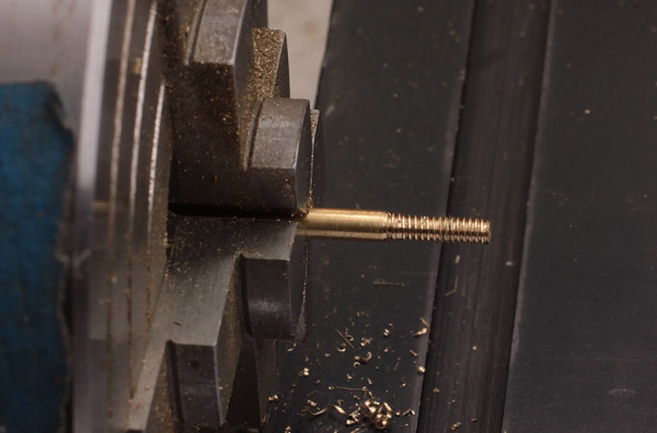
Note here that I have also shortened and dressed the end outside the hole. Yes, the lathe was spinning for this shot, but I did back the tool off a few thou to avoid rubbing.
49063-parting.jpg


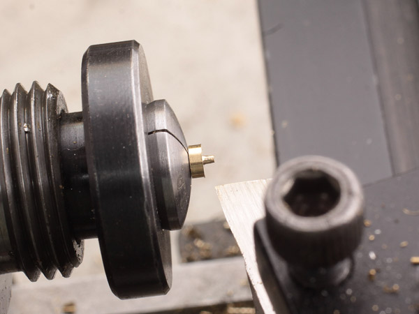
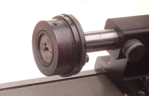
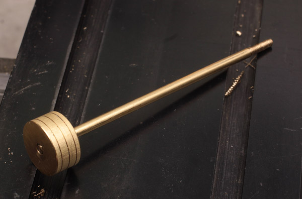
Here I have reversed it in a collet to dress the head. Must have been close on this diameter as well, as it cleared the reamed hole in the valve rod and was a light finger-press fit in the 1/16 collet.
49065-collet.jpg


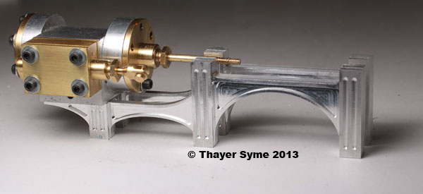
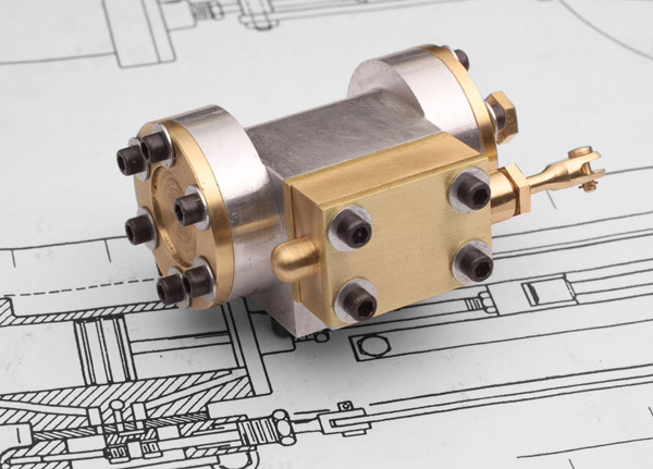
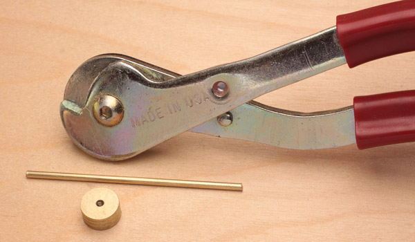
Everything needs a bit of a bath, but here it is, installed with enough room for a thin washer.
49078-pin-and-fork.jpg


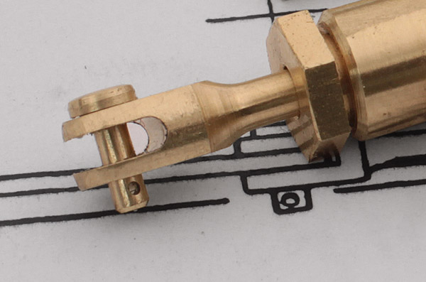
Yeah, that's the packing nut screwed into the valve chest. What's another few minutes, since we are on a roll?
 
All the valving / steam chest bits waiting for a home.
49076-steam-chest-parts.jpg


Coming together...
49078-partial-assy.jpg


And on the cylinder block.
49082-assembled.jpg


I agree, the oversize washers and SHCS look awful and they will go away. I made my first 2-56 test nuts today from some 1/8 hex stock and they look pretty good. Do you see any issues with making studs from 360 brass to match the heads and nuts, or should I go to 12L14? As much as I could try to justify a low-time guy like myself using Du-Bro's threaded rod, I don't think I can bring myself to do it.
49083-assembled.jpg


Yes, I know there is no way to get steam into the chest yet, but that will wait until I decide if I want to come in through the chest proper or its cover. Okay, the chest does make the most sense, since an engineer would want to be able to set the timing without undoing the feed. So now that I have sorted that out, it will just be a matter of where/how to feed it once I assemble it all.

Good night, all.
 
Well, I am back on Elmer's #33. I have been rather busy the last couple of weeks getting a new charitable business off the ground. It's not really relevant here, so I will just mention the URL in case you are interested, http://www.ribbons4sandyhook.com

Now to get on with the machining. I've not got a lot this time, just the piston and piston rod. Still, that's two more check marks in the done column.

The piston is pretty straight forward turning, so I will mention just a few things to go along with these three photos.

First I chucked up some half-inch stock using the indicator to get it as near to perfect as I could. I gave it a little polish with some scotchbrite before cutting the three oil grooves. Next came spotting the rod hole with a center drill, drilling and finally tapping for the rod using the tailstock chuck to hold the drills and tap. I have since learned that the best procedure is to leave the piston a few thou proud, add the grooves, and then turn it to final diameter. This cleans the burrs left by the grooving operation. My stock was already at size, so I guess I should have swapped the scotchbrite and oil grooving. Next time...
49089-piston-turned.jpg


The next tip I have concerns aligning the parting tool. If you have a nice clean face on your stock, why not take advantage of that "mirror"? This first image shows the tool up against the piston, and clearly misaligned.
49092-cutoff-not-align.jpg


Here you can see the cutoff tool is now parallel with the face of the piston and is certain to give much better results.
49093-cutoff-align.jpg


One last point of interest on this is that the apparent angular difference between the cutoff tool and its reflection will be twice the actual error.


Moving on now to the piston rod, I lopped off a piece of 3/32 stock using a humble, yet oft-used tool. These Made-in-America cutters are great for small diameter rod stock. They are designed for cutting hardened music wire, so our typical stocks won't stress them at all. I got mine from Stevens AeroModel, http://www.stevensaero.com
49120-cutter.jpg


I first chucked the blank in my 4-jaw, again indicating as best as I could. We want the rod and piston concentric, so don't skimp and use the three jaw.
49134-4jaw.jpg


After turning a sufficient bit on the end to 0.086, I single-pointed about 80-percent of the thread depth, ...
49135-single-point.jpg


... then finished off with a die held in Sherline's adjustable tailstock die holder.
49110-die-holder.jpg


49111-cutting-threads.jpg


These are the finished threads for the crosshead end of the piston rod. I then reversed the rod in the chuck, reindicated it and repeated to thread for the piston.
49136-finished.jpg


And the assembled combo.
49139-piston-assy.jpg


I don't know how true these need to be, but with the rod indicating a TIR of less than a needle width, the far end of the piston shows a TIR of just at 0.001. I have to believe that will be close enough.

Note that I've mucked with the design a bit and needed this slightly longer piston rod. The "frosting" on the piston comes from fine lines caused by pushing it back and forth a bunch by hand with the previous "short" rod.

Thayer
 
Last edited:
Hi Thayer

Love your step-by-step guide. This is helpful. Also love your photos. Veey instructive.

Vince
 
  • Like
Reactions: gus
The Evolution of an Engine
While I haven't posted in about a month, I have been slowly picking away at the engine. There hasn't been too much progress though, as I couldn't resist the urge to muck around with a perfectly reasonable design and to put a bit of my own stamp on it. Inevitably making a change to a proven design cascades into multiple changes and consumes more time.
0-ev-profile.png


Elmer Verburg originally drew the crosshead guides as simple rectangular bars and then offered up two variations as shown below if you wanted to put in a little extra time and energy to pretty it up a bit. He built his own engine with the cut away straight arch as shown above.

1-originals.gif


I liked that look quite a bit and figured this would be a chance to take advantage of my CNC capabilities. The fourth option above was my first look at using an elliptical arch on the crosshead guide, something that would be a challenge to mill conventionally. I liked the basic concept and decided to take it a bit further.

Elmer’s original mill engine has both a base and sub base of 1/2-inch thick stock, intended to simulate the rather stout cast bases of the original engines. This all in keeping with the scale and mission of the full size inspiration. After a bit of doodling I realized that by eliminating the upper base I would have another half an inch to work with and a lot more opportunity for fancying up this build. This next image shows my first passes at the main crosshead support arch, first as a straight arch, then with a pocketed web and the first hint of some feet.
2-first-tall.gif


Having that extra space inspired me to envision some of the grand industrial revolution engines of the 1800s and soon I was sorting out some elaborate bridgework that might give the impression that I was modeling a much larger engine where a monolithic casting might be considered too expensive, heavy or technically challenging. In the image below my design has now moved on to a column structure with a webbed spandrel. The single flute being dictated by my smallest ball end mill at 1/16. The lower image came after the inspiration to join the crosshead guide supporting structure with the cylinder support.
3-double-cylinder.gif


The above was looking good, but I felt it too severe and didn’t know how to fix it right away. In the end I took a page from the Stuart and PM Research catalogs and opted to cantilever the cylinder.
4-cantilever.gif


Next up was the fluting. Should the columns have single or double flutes? That’s an easy one, since I was already making it fussy, why not make it more so? You can also see the first indication of the column bases. Just a simple quarter round cove and a mortised pocket on top to accept the tennoned columns.
5-ones-or-twos.gif


But should all columns be the same weight? Here I am trying out combinations of single and double fluting. Note the crosshead spacers are also different, as try to find the solution there as well.
6-ones-and-twos.gif


In the end I decided double fluting all around and as you can see have also extended the spacing between the cylinder and the crosshead to make it feel less crowded. Also noticeable is the extension of the crosshead columns to now incorporate support for the upper slide directly. As the main structure will be milled out of aluminum I also plan to attach a steel or brass plate for the crosshead to ride on.
7-final.gif


This was a classic case of seemingly simple changes compounding to consume an exponential amount of additional time. Almost every new version had many more options that would need sorting out. Since most of this design work happened late at night it also meant continuously finding “issues” in the drawings that needed attention before I could actually go to the mill.

Next time I will talk a bit about the programming and actual milling needed to carve these bits from aluminum. I will leave you with this little teaser though. You can see the bits of bridgework starting to emerge from a piece of aluminum plate here.

49819-milling-bridges.jpg


Thayer
 
Yes i see it is.Very impressed with your workmanship at small scale level.
When i built a 31/2 G loco i just bandsawed a piece of hardwood for drilling the steam ports
but i took the easy route and bought castings.No CNC but the overall picture is the same
Congratulations on your posts. Very informative BAZMAK
 
Hi Thayer,
just found your build log. Your step by step is indeed very nice and that Sherline kit sure does nice work with you behind the wheel :)

Your cylinder assembly looks fantastic. Looking forward to you working on your design changes to come. Nice CAD work too.
Gerry
 
This is a busy time of the year in my schedule. What with a trade show, Pinewood Derby and a 20+ year commitment to an annual charity event, my shop time has been pretty limited recently. I have made some progress though. Here are a few photos of milling the bridgework.

First up is a test shot from a piece of wood. It only costs a little time and finding errors here is a lot easier that in metal. It looked good so I bookmatched the file and output it again for another go in aluminum.
A-wooden-bridge-49142.jpg


A trusty Jolly Rancher wrapper comes in handy while setting Z0 on the stock. Note the A2Z hold down clamps. This operation is for spotting the holes for 6x 6-32 SHCS that I used to hold it down while machining.
B-49816-z0.jpg


Here is some of the early milling. The 1/16 ball end mil was first, setting in the flutting. Now for profiling with a 1/16 end mill.
C-49820-milling.jpg


The basic texture was completed with a 1/16 end mill. Now to cut it free from the raw stock with an 1/8 end mill.
D-49696-16EM.jpg


Part way through. This section makes a good mess, so keep the coolant flowing. I used denatured alcohol in a spray bottle. A bit expensive, but it really helped keep everything cool.
E-49698-mess.jpg


The first side and profile are complete. Now to swap it and mill the second side.
F-49822-side1.jpg


Here you see side #2 getting started. In an ideal world I would have used a pair of close-fitting pins to register the stock when I flipped it over but the half dozen SHCS did the job well enough.
H-49823-side2.jpg


The final part rough from the mill.
I-49826-rough.jpg


Here I’ve separated the two halves, cleaned up the ends and have now mocked it up using the cylinder assembly.
J-49832-mockup.jpg


Back to the job at hand. Here I am drilling the column ends …
K-49840-drilling-caps.jpg


… and tapping them for the 2-56 studs, yet to come. A small stop screwed to my vise makes an handy reference for locating the second piece.
L-49842-tapping.jpg


With the holes centered and tapped, I milled a tenon on the ends of the columns to reference the feet/caps to come.
M-49846-tennon.jpg


Here are feet being milled from some 1/16 sheet stock. First the half round with a 1/16 ball end mill to create the cove, followed by a 1/16 straight end mill to create the mortise, clearance for the studs and finally, to define the perimeter.
N-49707-feet.jpg


I cut a couple tests, reprogrammed a little to retain them on one side, then ran the 10 that I need.
O-49709-feet.jpg


All up to date, here is how it looks now. The cylinder assembly and bridgework is secured to the base.
P-0801-assembly.jpg


It is good to be back on it. I have the bearing supports drawn and will be milling them in the next few days.
 
Last edited:
Really fine work Thayer. Thanks for the excellent photo documentation.

Phil
 
Moving on to the bearings, it made sense to continue the theme that I established with the bridgework so I sketched up some pretty curves and pockets in Graphite. D2nc does support pocketing, but not yet islands, so I had to do a bit more drawing in Graphite to generate the tool paths before exporting the DXF. These parts are pretty small, so it wasn’t too tough to sort it all out. I also did a bit of manual coding after converting the DXF to G-code in D2nc to create some custom ramping and retaining tabs. Yeah, I know D2nc now supports ramps and tabs, but I have only just recently downloaded the latest version and I am not yet up to speed with it.

This first image shows a piece of 3/8-inch stock secured to the tooling plate I made up when milling the bridgework. I first clamped the stock down and dimpled it with a center drill to mark holes for the hold downs as well as the center two which will ultimately accommodate the main shaft.
52271-plate.jpg


I’ve mentioned previously that I am a bit of a chicken at times and here again I am making just a light skim cut, taking off .002 with a 1/16 end mill to confirm that all looks well before committing to the full depth.
52274-chicken.jpg


Since it looked so good with a skim on the pockets I switched to a 1/8 end mill to trace the outlines. Yes, the paths overlap a bit at the bearing heads, but they don’t interfere in the actual parts.
52277-chicken2.jpg


The test skim looked good, so here I am committing to the pocket on the outboard bearing. I am cutting at 10,000 rpm, 30 ipm, with a .010 DoC. You can see the island starting to appear in the pocket. I am using denatured alcohol in a plant misting spray bottle to remove chips and keep everything cool. It also does a great job of removing the blue dychem.
52283-getting-started.jpg


Both pockets are cut and with the test outline trace you can see pretty well what these parts will look like. The elliptical islands will be hollowed out shortly.
52290-side1-pockets.jpg


And here we go again. I flipped the stock and am now pocketing the other side.
52294-pocketing-side2.jpg


Once the pockets were done I switched to the 1/8 end mill and am now opening up the islands. Why is the cutter in the midst of the pocket? I took advantage of the long axis, ramping lower into the stock while traversing the ellipse after each circuit.
52300-thru-holes.jpg


All clear in the holes, so now just the perimeter to do.
52303-pockets&holes.jpg


Thayer
 
Last edited:
Luv that thread... An high quality one, with very good quality pics + it demystifying things for the ones that never see a casting kit. Congrats and thanks for sharing! Maybe, as you're saying yourself, not an expert machinist (I'm far to know enough for judging :D) but for sure a very good teacher!
 
B-Train, thanks very much for your kind words. I've always fancied myself something of a teacher, so it is encouraging to know that I may not be far off the mark.

Continuing on from last night’s post, and still with the 1/8 end mill, here I am well into outlining the smaller bearing.
52310-perimeter.jpg


Both bearings are now outlined. I left a couple .030-thick tabs on each part to keep them in place.
52312-cut-finished.jpg


I flexed the pieces free of the parent stock, then trimmed and filed away any evidence of the retaining tabs. Here the smaller bearing is held inverted in the vise using 1/4 lathe tools as parallels. Be sure to mic a handful of tools to find a good pair. I was surprised at how much they varied.
52316-vise.jpg


I next drilled and tapped for the hidden retaining screws. Note that the left hole is finished and taped while I am only now starting on the second hole. No point in changing the setup until all operations are done for a given location. Yes, I did rotate one of the lathe tools after the above photo. I realized I had positioned wrong right before I started drilling and tapping.
52318-drilling.jpg


And here is the engine with the rough bearings in place. There is a bit of work to go yet on these pieces but I had to try them on for size. I like this view and how it shows off the overall lines. I will definitely be contouring them a bit on the faces so they are not so planar. I will also bore them for bronze insert sleeves.
52332-assembly.jpg


Full disclosure? What I don’t like is the slight gap under the closest edge of the bearing sitting on the base, thanks to the business end of my 2-56 bottoming tap which is still in the part. The bearing is currently sitting in a solution of Alum, simmering away. I could have just remade the part pretty quickly, and fully expect to do so anyway, but I wanted to give chemistry a chance first.

This view also highlights the need to flute the end faces of the bridge columns.
 
Thanks Chris, alas though, not any more. At least for now.

When we last left the shop I had a pot of alum solution simmering away with a broken tap encased in partially milled aluminum. I nipped on down to give it a check right before turning in last night and decided the 12 hours it had seen so far was close enough. So, how did it all turn out?

Well, not quite as I had hoped. When I opened the lid there was a peculiar odor and a faint stream of bubbles rising from the offending area, but there were stronger streams rising pretty much everywhere else. I don't know if I had it too hot, too concentrated, or what other parameter was off, but as you can see below, I made a proper mess of the entire part. The tap was in the larger hole to the right, and in fact a good part of it still is.

alum-52336.jpg


I've been doing a bit of redesign on these parts since milling them anyway, so I'll start on a new set next time in the shop. Once I saw them I decided they were a bit "monolithic."

Thayer
 
Last edited:
Good for you for trying to get the broken tap out....I tend to throw the part across the shop when it happens to me.

It doesn't get the tap out but somehow I feel better afterwards.
 
Well, not quite as I had hoped. When I opened the lid there was a peculiar odor and a faint stream of bubbles rising from the offending area, but there were stronger streams rising pretty much everywhere else. I don't know if I had it too hot, too concentrated, or what other parameter was off, but as you can see below, I made a proper mess of the entire part. The tap was in the larger hole to the right, and in fact a good part of it still is.

your doing nice work man , as for your aluminium getting like this are you sure their was no sulfuric acid close by???
I did use this method alum on aluminium and never encounter this but I always did it in the open not with a closed lid
 
Luc,

As for the acid, none that I know of. I mixed up the alum in a small pyrex bowl, placed it on a coffee cup warmer and used the next bowl size up as a close fitting cover to control evaporative losses.
 

Latest posts

Back
Top