Elmer's #33 - a novice makes chips

Home Model Engine Machinist Forum

Help Support Home Model Engine Machinist Forum:

This site may earn a commission from merchant affiliate links, including eBay, Amazon, and others.

thayer

Well-Known Member
Joined
Aug 16, 2009
Messages
207
Reaction score
84
As a bit of reintroduction, I've had a manual Sherline 4400 lathe for a while and a couple years ago complimented it with the A2Z CNC Monster Mill to maintain Sherline compatibility. Knowing little of operating a mill or CNC at the time, after a few basic bits and pieces I christened it with a couple of Elmer's simple engines, a #25 wobbler followed by the #2 twin vertical wobbler, seen here.
http://www.homemodelenginemachinist.com/f14/elmers-2-25-a-8201/

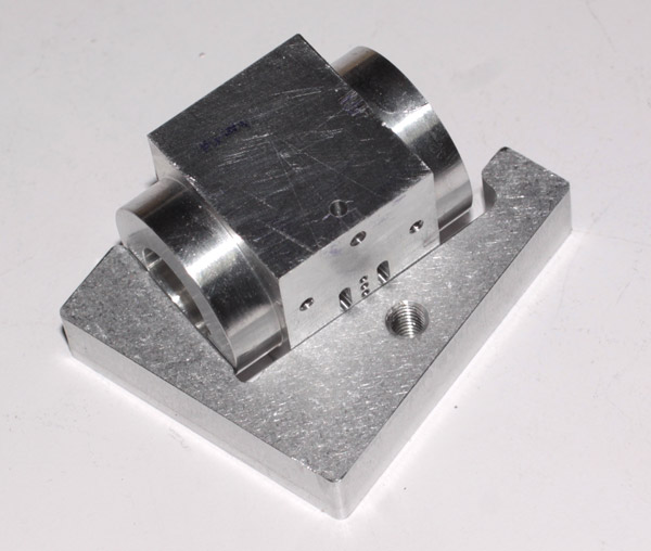
While the main use of the tools has been making bits and pieces for my radio control airplanes, I have long meant to revisit Elmer's catalog and tackle something a bit more complex. A few days ago I did just that. I've now begun his #33 horizontal mill engine and began with the cylinder block to see right away if I was up to the challenge. I'm not fast with my projects, but try to build cleanly and accurately. I will update this thread as I go but am rather sure that life will keep it from running this year.

My main goal, beyond finishing the mill engine of course, will be to pass along a bit of inspiration to others like me who are new to machining. This forum can be at once both inspiring and rather intimidating. I've found twice in the past, and expect to again, that you don't need to be a master machinist to enjoy turning out a working steam engine.

a-100_0524.jpg


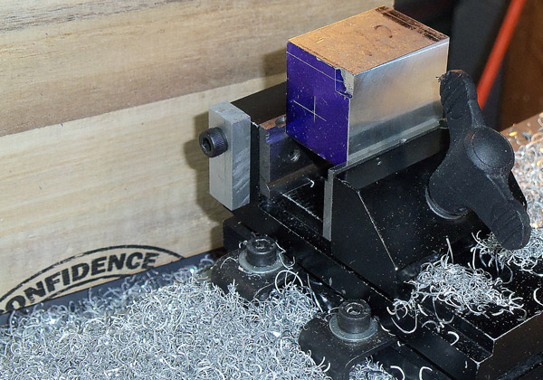
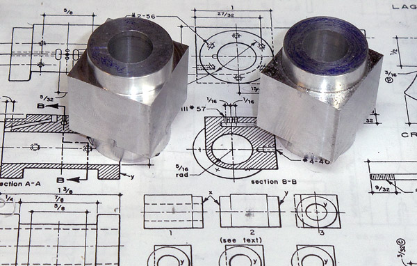
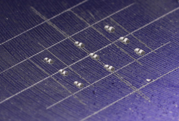
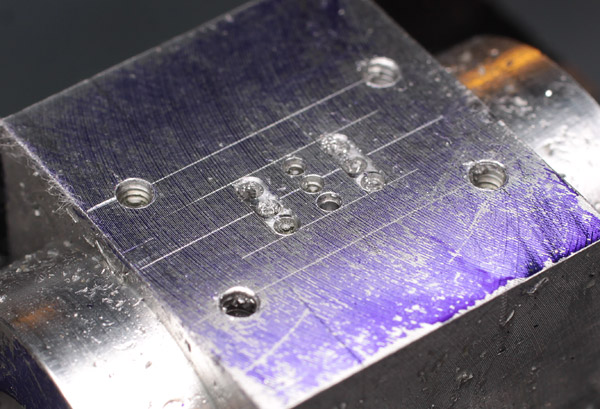
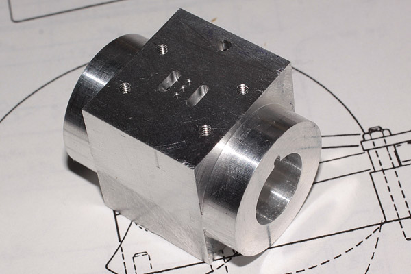
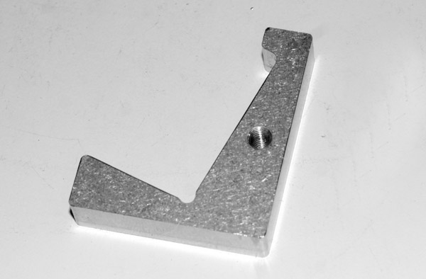
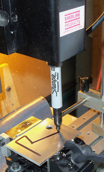
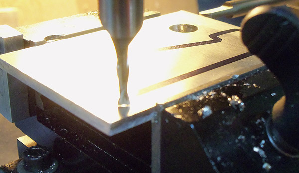
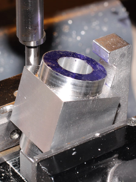
This first photo shows the basic start. My scrap stock was a little oversize, so I made a several passes with the Sherline flycutter to bring it down to its nominal cross section of 1x1 inches. Note the slight relief in the top of my vise jaws. Inspired by Tryally's slim vise, I inverted the stock jaws and milled the relief as a "permanent" set of parallels. I will occasionally skim them when I can't indicate them accurately. Note the layout ink and scribing. I decided to lay out this project as accurately as possible, despite the availability to just use the DROs and run some G-code.

Of note to those still sitting on the fence is the piece of wood used to contain some of the fly cutting swarf. I have a stash of used breaking boards from our local karate studio, gathered after one of their semi-annual black belt testing sessions. If an 8 or 9 year old kid can earn an internationally recognized black belt after 4 years of training, surely we can muster enough confidence to carve a little aluminum and brass.
 
Last edited:
The trued-up 1x1x1.375 cylinder block back in my lathe and ready for boring. I am using a cheap import drop indicator to set the 4-jaw for the appropriate 1/32 offset for the cylinder. I did an initial center by eye using the concentric rings, then indicated opposite faces to bring it in tight before offsetting for the bore.

b-100_0526.jpg


I used this same setup to clean up the ends of the rough sawn blocks and face them to length. Careful adjustment of the rough block in the chuck allowed me to maintain it parallel to the bed within half a thou along its length when I originally faced it, and again now. Surely that will be good enough for this project.

FWIW, the shop-made indicator holder is that shape because I had an offcut about the right size.
 
Last edited:
Step three was opening up the bore. I started with a center drill in the tail stock, then stepped up .040 - .050 at a time until just shy of .400. I then used the largest Sherline boring bar to bring it out to .500.

c-100_0533.jpg


I actually left it a bit shy to give me some room for honing the cylinder after finishing the rest of the operations on the block.
 
Last edited:
The outside of the cylinder gets turned round for .25 on each end and I didn't think I could safely hold it to turn the second end without ripping it out of the jaws or mucking up the first.

I ended up making a slip-fit mandrel from 12L14 steel, first using a steady rest to center drill the ends. I then turned it between centers to size.

d-100_0528.jpg


d-47719.jpg


d-47720.jpg


To hold the cylinders, I left the center in the headstock and replaced the lathe dog and faceplate with the 4-jaw. With the mandrel back on centers, I lightly griped the block to hold it while I turned the second end.

e-100_0532.jpg


I know better and should have padded the jaws before turning the second side. I didn't tighten them much, but the hammering from the interrupted cut was enough to give me something to polish out later.
 
Last edited:
Here are two cylinder blanks bored and ready for the valve porting.

f-100_0535.jpg


I did a pretty careful job of laying out the ports and it was a good thing too. Somehow I missed on my edgefinding operation by a bit. Before spot drilling the 13 holes for the porting and steam chest mounting, I dimpled the face about .005 to make sure I was good to go with the drilling sequence. My first pass showed the error so I rechecked the edge and got within a couple for the next round. You can see the second round of smaller dimples are a lot closer in Y and nearly dead nuts on for X. They are intentionally smaller so I would know which was second set.

g-47456w.jpg


I figured that was close enough and pressed the go button. Spot drilling with a #1 center drill, followed by peck drilling sequences for the intake and exhaust ports, and steam chest.

h-47460w.jpg


The holes all fit within my layout lines so I think it is pretty close. The step in the exhaust port bores comes from the center drill being slightly larger than the final bit and going deeper than I needed to. The intakes have an .005 skim as well to check the G-code.
 
Last edited:
I've been admiring everyone's dedicated taping stands on HMEM and can certainly see the appeal of such a project. I haven't gotten to it yet, but did upgrade my tapping capabilities on this project.

Previously I had placed my lathe center in the mill headstock then jogged it down onto the top of my tap handle. Tapping meant one hand turning the handles with the other on the keyboard chasing with the center. As you can imagine, that was pretty slow and didn't do a great job holding the handle steady.

To improve my tapping going forward, I took an 18x.312 stainless shaft I salvaged from an old printer, turned a 60-degree center on the end and bored out an unused tool holder to just clear the shaft.

i-47718.jpg


Now I set up much the same way as before, but thread the 5+-ounce stainless shaft through the spindle and let gravity feed it as I advance the tapping handle. This works beautifully well and is a lot faster than the old method. In essence it is poor-man's version of the spring-loaded center often used.

j-47714.jpg


If you get the bore in the holder a little looser than you wanted, you can turn a drop-in collar for the upper end of your Z-axis spindle as well. I haven't done that yet and am taking solace in that this new setup has a lot less slop than I had with the previous method.
 
Last edited:
Next up is drilling the long diagonal ports. I used a digital TiltBox to set the cylinder at the proper angle. I doubt it is all that accurate, but I don't have a sine bar yet and the tolerance for this op was pretty loose.

l-100_0537.jpg


I then used my height gauge to determine how deep I wanted to drill. I measured off the notch in the inclined lip of the cylinder bore and the target port.

m-100_0538.jpg
 
Last edited:
Last but not least, the current status of the cylinder. Yes, I have a second block but that one has a way to go to catch up. Hopefully I won't need it for this project.

n-47710.jpg


For anyone working on one of Elmer's designs, carefully check the geometry of the notch in the end of the cylinder. He calls for a 1/32 offset* but I could not get the drill to catch in the bottom with that dimension. At 1/16 I had no trouble. The image shown is the end with the larger offset.

o-47712.jpg


That's all for now. I am quite pleased with my work so far and think it looks pretty good, despite the harsh lighting.

*I have now realized that I had read the print wrong. The indicated 1/32 dimension is for the centerline of the port, not how far into the cylinder wall it is offset. That all makes a lot more sense to me now and I now believe the photo below shows the porting as Elmer intended.
 
Last edited:
I got into the shop briefly this evening and have some stuff I will post later since it is late now. In the meantime though, I have a little quiz. Can anyone guess what this little piece of aluminum is all about?

p-47732.jpg


Its outside measurements are roughly 1.6x1.9x.375 inches with the hole at 10-32. And yes, it is related to this project.
 
Last edited:
I created CAD models of this engine but I don't
Recall that as one of the parts. I went off the plans
from the Jon-Tom site. Where did you see this
on the drawings?

John
 
It is not on the drawings. Just something I whipped up last night.
 
An arm mounted horizontally that transfers motion from the crankshaft that controls the intake and exhaust
 
Partly close Rob. It does control the intake and exhaust, at some level, but not like you describe.

Before the reveal though, here are two little layout / test tips I find useful as a timid beginner. My mill is CNC and I will usually "cut" some air before committing tool edge to metal. If you have a piece of stock that is a little marginal in size, or just want to see your robot run a bit to give you confidence, you might appreciate that a standard Fine Point Sharpie can be securely seated in the #1 MT of a Sherline spindle. This gives you a pen plotter of sorts. Seeing ink along the toolpath on your actual stock, secured to your table, buys a lot of confidence. At least it did for me.

Step one is to manually edit your g-code to make one lap around the path at Z0 minus a few thou. I will usually bump the speed up a bit as well. Jam the Sharpie into place, then start the spindle at a slow speed and apply light pressure with your fingernail or some sort of stick to true up the wobble. You don't have to get it perfect, just slow down the big swirls. Set your Z0 with the tip just touching down and then press the go button.

q-100_0541.jpg


The path you see above was with a bit of wobble going on, but it left a path about an eighth wide which happened to correspond to the end mill I was using. This made it an easy task to confirm that the mill would not crash into the vise before I started cutting. Yes, this is thinner stock than the part you saw previously. I made two, the first from .125 stock which I decided was not thick enough. It worked, but I knew it could be better.

If you really want to get fancy, you can draw the part in one color and the tool offset in another. Don't forget to reset your g-code, Z0 and feed rate before you start cutting.
 
Last edited:
When it comes time to set your cutting tool to Z0, getting it to "just" touch down on your stock can be a little intimidating for a beginner. You read about auto probes, cigarette paper feeler gauges, 1-2-3 blocks and even candy wrappers being used. (http://www.homemodelenginemachinist.com/f13/beginners-tool-box-19342/index3.html#post201449)

Truth be told, when you are going to cut through a piece of stock the Z isn't really all that critical. I will usually bring it down close, then jog down .001 at a time using my keyboard. While bringing it down I rock the spindle back and forth using the Sherline #2049 handwheel and just watching for the first light mark or curl at the cutting edge. I'll call that first touch Z0 and proceed.

Jogging at .001 as you feel for the surface can be slow going though, so I usually make a slow Z move to get the tool as close as I dare, hopefully just above the surface. A strong backlight provides a nice visual aid letting you easily see the gap between the tool and the stock. If the surface is reflective, don't forget that the tool and its reflection are 2x the actual height apart. Here is a photo showing the tool hovering just a few thou before touchdown.

r-100_0543.jpg
 
Last edited:
Does this help?

s-47733.jpg
 
Last edited:
As you've no doubt sorted out by now, it's just a simple little cradle that lets me set the cylinder block at the proper angle for drilling the steam passages between the cylinder and porting. Just press the cylinder into the seat against the base of the vise and carefully it snug up.

Elmer used that cylinder design for several of his engines so the odds are pretty high that I will be drilling these passages again in the future. I wasn't completely happy with the first one and I've already got a second cylinder blank that may go on his #29 Vertical Mine engine next. This seems like a better way to go and likely more accurate than the TiltBox which calls out a +- 0.2-degree tolerance. Even if the angle isn't perfect, it will be more consistent.

Finding Y0 comes from indicating the edge of the block, making a few measurements of the actual part and doing a little math. Centering this passage is not critical so if I miss center by a little it really doesn't hurt anything beyond my pride.

t-47724.jpg


The part I thought was brilliant for a beginner, if I do humbly say so myself, was coming up with the little nub above the cylinder to set my X0.

u-47729.jpg


Touching off that with my edge finder puts my spindle directly above where I want to come in with the 1/16 end mill to start the passage.

w-100_0551.jpg


Actually cutting this part took 8-10 minutes after I had it designed (Ashlar-Vellum Graphite) and generated g-code (d2nc in Mach3). I was feeding at 16 ipm with a .020 doc. The stock was a scrap of 3/16 aluminum tooling plate. The finish of the cut could be better, obviously from letting the chips sit in the slot while I chased around it. I used TapMagic applied with a small plastic pipette and tried to clear the chips as best I could with an acid brush. I could clean it up with a finishing pass but doubt I will.

The cylinder with the dychem on it is the undrilled blank, the one posing under the mill in the A2Z holder is the first one I drilled. I indicated that one just to see how close I could get the mill and it looks near enough with my Optivisor.

Oh, and the tapped hole? Sorry for the misdirection. I have no idea why it is there. It was in the stock when I got it.
 
Last edited:
I'm a Sherline user and love all the pictures !! I've still not machined anything serious on my Sherlines and I've had the lathe and mill for 5+ years now. Gives me hope that I can really start using them :)

Mike
 
Mike,

I find the Sherline gear very capable, you just have to be less ambitious than you might with speeds and feeds on a larger machine. And of course, be working on smaller parts. Elmer's series of engines are very manageable on Sherlines and you can make some very nice pieces with them. Start with something simple like his #25 Wobbler. It is a popular first engine and while maybe not as appealing as other options, it does boost the confidence significantly as it comes together and finally runs. When I did mine it was the first complex, multi-part project I had done in metal as well.

Thayer
 

Latest posts

Back
Top