Elmer's #33 - a novice makes chips

Home Model Engine Machinist Forum

Help Support Home Model Engine Machinist Forum:

This site may earn a commission from merchant affiliate links, including eBay, Amazon, and others.
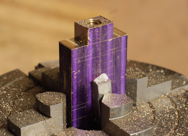
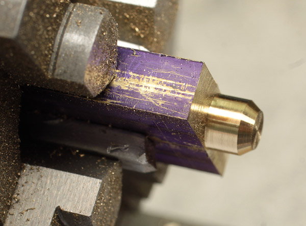
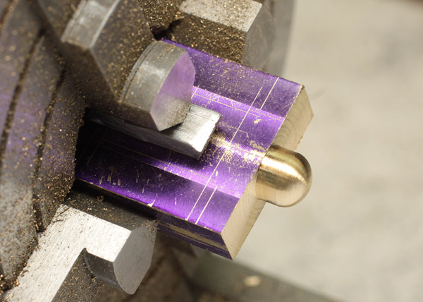
Sharp eyes above will also notice that I rounded the cylinder.

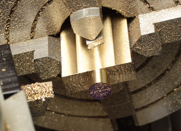
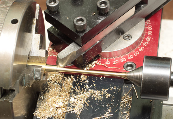
The way to do this was with my rotary table, so I first indicated both Y & Z along the phantom lines with my Interapid. I had about a 2-inch run without hitting the outer chamfer or the centering ring so I was able to get it pretty close.

Indicating-RT-47859.jpg


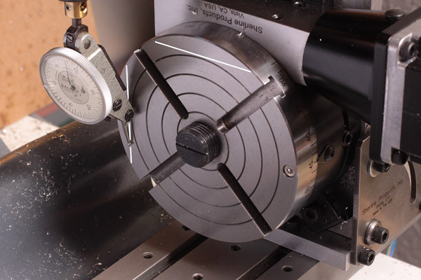
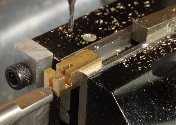
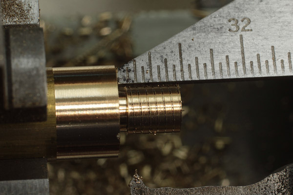
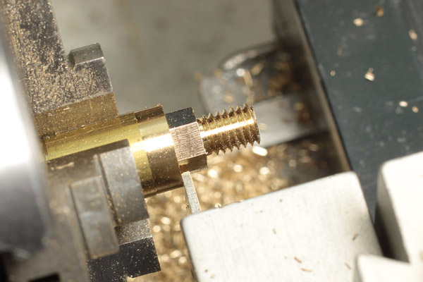
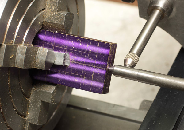
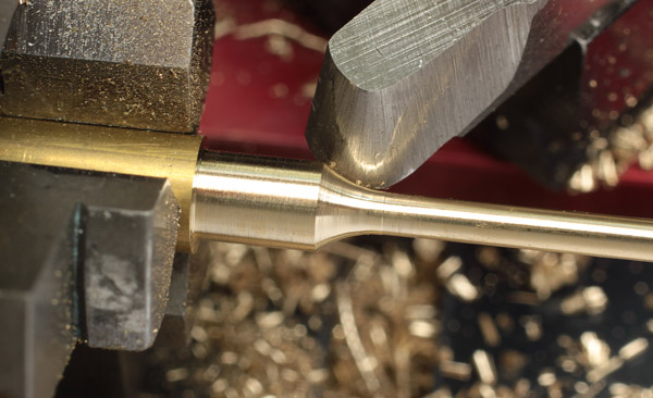
Next I gripped one end of the cylinder in my split bushing and used the lathe to get the 4-jaw close. I later fine tuned it on the RT because I know the threaded chuck mount misses center by a thou or two. Some beginners can be intimidated by a 4-jaw independent chuck but I find it is actually pretty easy to use. eyeballing the alignment within .010 with a bit of practice is quite doable and truing it up from there is pretty quick.

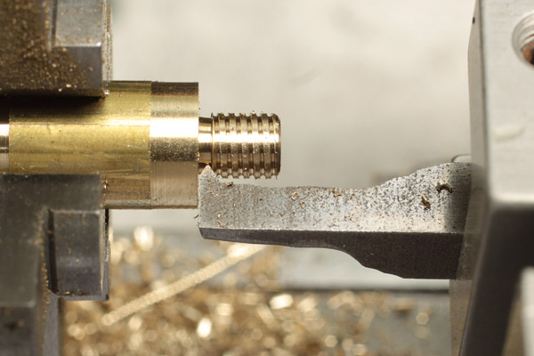
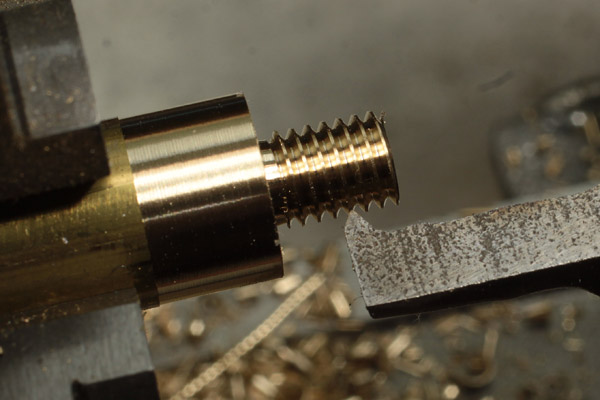
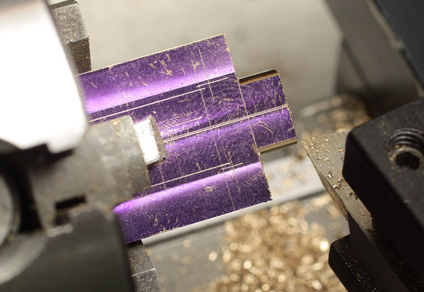
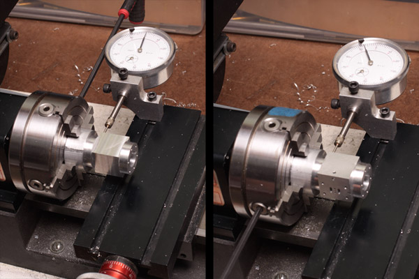
In the left image below I am zeroing the indicator with one pair of jaws horizontal. Once I do that I use the hex key to rotate it 180 and note the runout, shown on the right side at about .008. I now insert a ball driver into the far chuck and tweek the two jaws at the same time to split the difference. With that done I rotate the chuck 90 and repeat with the second jaw pair. A final check on the first pair will usually show it well within what I need before moving it to the rotary table for final truing. I've done it a few times now and can get to within .001 TIR within a minute or so. Not as fast as a centering 3-jaw, but a lot more accurate.

clocking-4-jaw-47857.jpg


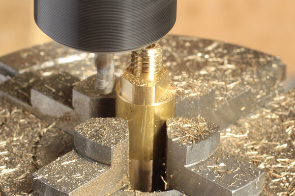
With the chuck moved I have to spin the RT to fine tune the centering and this is a great excuse for a CNC RT. I wouldn't want to hand crank it around too many times centering the chuck.

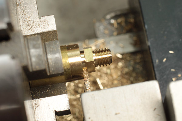
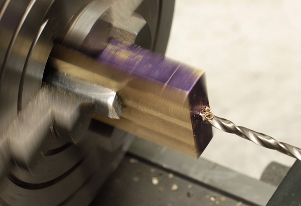
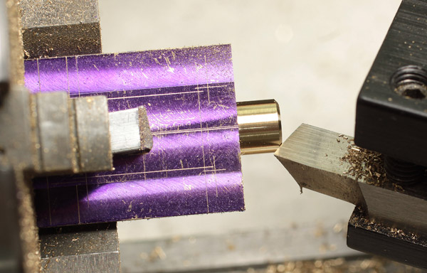
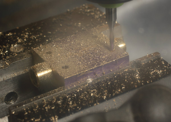
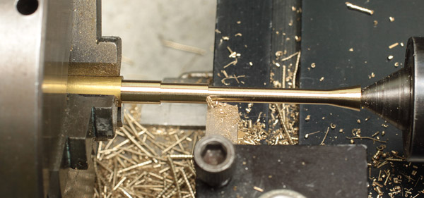
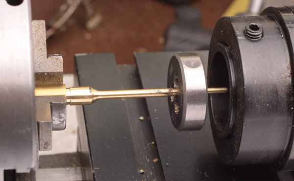
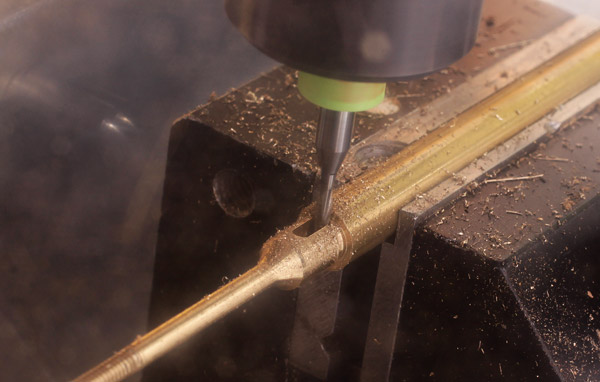
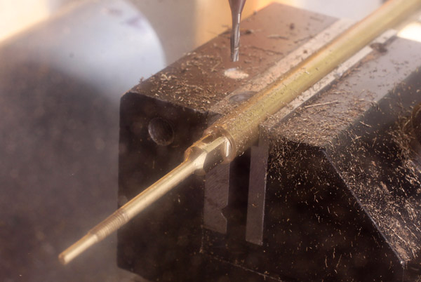
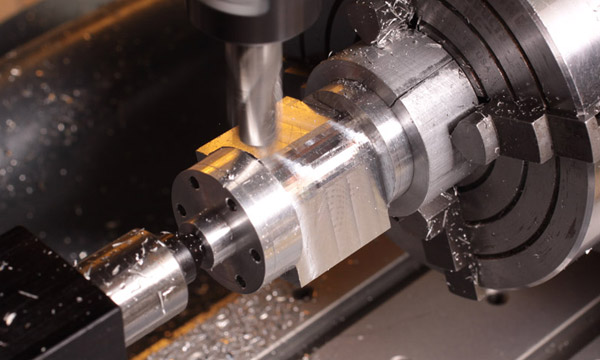
You can see below that I used one of the aluminum heads and Sherline's adjustable tail stock to support the outer end of the cylinder. I don't know if it was necessary with my light cuts, but it did make me feel better. No point risking that many hours to find out I should have...

rounding-47862c.jpg


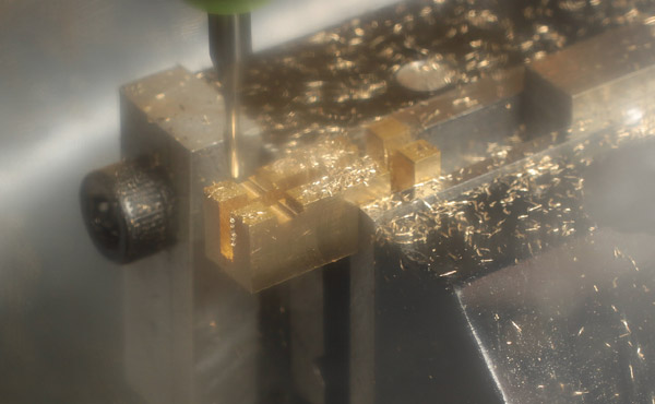
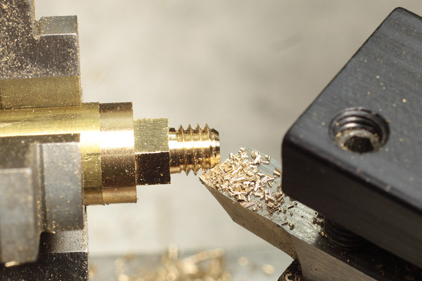
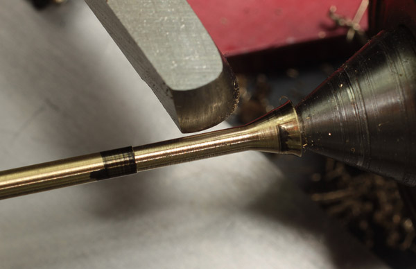
I hand-wrote a little G-code file to clean off the corner of the cylinder first at 45 degrees to the original reductions and ultimately stepping around to 16 facets through the 90 degrees. From here a little quick file work got it ready for primer.

As always, let me know if you have any questions or if I am doing anything wrong.
 
Last edited:
A little more progress over the last couple of days. First though, a question. I have been posting text and then the images that relate to that text as that is the only way I can see to do it. Yet in other posts I see text and images intermingled. I would much prefer to embed my images but don't know how. Can anyone offer up a few tips? Thanks.

Hi Thayer! Your engine is really excellent. I cannot offer any advice on the machining aspects, but I can maybe help a little with the pictures.

I think you are "attaching" the images, right?

In order to embed the pictures into your text, so that you can write text before and after the images, you will need to use a photo hosting service - an intermediate site.

At first, this can appear a bit intimidating and overcomplicated, but once you've done it there are some significant benefits to posting pictures this way.

There are several free photo hosting sites, and some that offer extra features if you want to pay a yearly membership. To start with, it's worth signing up with a free one to see what it's about. Photobucket is a good way to start. www.photobucket.com

Basically how it works is that you store images on the photo site, and then post a link to the picture in your post.

You can see an overview of how it's done in a little thread I wrote here:

http://www.homemodelenginemachinist.com/f27/how-post-pictures-hosting-site-such-photobucket-19453/

I hope this helps - let me know if you have questions. One advantage of doing pictures this way is that you link to the same pictures from multiple forums and threads, so you only have to upload the picture once.
 
Thanks, that makes a lot of sense now that I think about it. I've now got it sorted out and will go back and embed the images as I can to help keep my logic obvious.

Thayer
 
Last edited:
Thayer, I have had a quick browse through this thread, and am impressed yet confuse; due to the high calibre of this project.

Of course I cannot offer any advice, as I am yet a 'blank canvass' in relation to maching.
Hopefully by following HMEM - I'll be able to learn and indulge on a craft I most certainly would like to grow as a hobby.

I look forward to seeing how this project comes along!
 
I'm not sure why, but for some reason I have been intimidated by the idea of making the valve. The only reason I can think of is because I don't have slitting saws. Well, I gathered up my courage and got into it tonight, starting with a piece of .375 sq stock about .75 long that I milled down to .250 x .220 with a 3/8 end mill.

dim-stock-48003.jpg


I left it a little tall just to give me more working room in the vise. Figured I could knock down the fingers once I was done.

dim-stock-48004.jpg


That went well enough that I decided to push on. I used one of the wizards in d2nc (a fantastic addition to Mach3 by Graham Hollis) to generate the code for the pocketing, referenced off the near corner of the stock, jogged in 3/64 and pressed the go button. Sure enough, just like the scrap of wood I ran it on first to settle my nerves, the brass soon had a pretty little pocket in it that measured to the dims on the plans.

port-1-48006.jpg


The bar coming in from the left gave me a position reference so I could end-for-end the block and cut a second one in case I needed it later.

port-2-48009.jpg


30 seconds or so later, the second pocket was done and it was time to face the fingers.

slotting-48012.jpg


Again I set up the stock using the stop so I could swap ends for the second. I had to hang it out the end of the vise so I could mill the slot for the rod. Since I do know enough to know that you don't want an asymmetric clamping load on your vise, I used a .25 sq. tool blank as packing for the other side of the jaws.

slotting-48014.jpg


Did I mention yet that I can be a bit of a chicken some times? I was confident I had done all the math right, but given the hour, I decided the extra stock thickness could serve a purpose. I modified my g-code to take a .005 cut to show where the nut and rod slots would end up. With great relief I didn't see any gross errors and proceeded to cut the full depth.

slotting-48015.jpg


Here is the first one all slotted to spec.

slotting-48017.jpg


Cutting the second end, photographed in action through my acrylic shield. The transverse slot is for the valve rod which measures .086, hence the step you can see. For what it is worth, I stepped down .010 on each pass and the 1/16 carbide mill didn't seem to complain.

parting-48020.jpg


Since I had enough stock between the two parts and don't have a slitting saw, I used the 1/16 end mill to cut off the valve to length. Again, photographed through my chip guard. I don't have a photo of the last step, trimming the fingers to length. I just put them side by side in the middle of the vise and passed back and forth with a 3/8 end mill until they were the right height.

finished-48023.jpg


And the fruits of my labor, ready for some final cleanup and smoothing of the face. I love how the light plays between the fingers. Almost makes the one look precious. As I always knew, they weren't hard to make at all and I now have g-code that will let me knock them out pretty quickly next time I need a few.
 
Last edited:
Hi Thayer,

The slide valves were very well done. You have just raised the bar(Standard) for me to catch up.
Gus is no good for fine details as I get impatient and work too fast.However my current QCTP which my second is doing OK with no rush and every step preplanned with Work Instructions on paper.
 
Thanks Gus,

One thing I know about myself is that if the main goal is the completed project it better be simple enough for me to sprint through it pretty quickly. On the other hand, if I get to the workshop only planning to make one thing, like say some nice slide valves last night, and do that reasonably often, it won't too long before it is time to assemble my new engine kit.

Thayer
 
Well, now that Santa has come and gone I can get back to the shop.

Next up is the packing nuts for the steam chest and cylinder. I figured it only made sense to make them both at the same time since they are identical, save the bore size. The final size is 1/4 inch across the flats, so I started with some 3/8 brass and threw it in the 3-jaw chuck since I had plenty of room to true it up. As much as I enjoy the challenge of dialing in the 4-jaw, there really is no good reason to do so when the 3-jaw is up to the task.

1-raw-3-jaw-47954.jpg


2-blank-4-jaw-47956.jpg


Here I have cleaned the OD, turned down the spigot to 0.188, drilled the center hole and milled the relief in anticipation of threading. Yes, I have the stock in the 4-jaw now and for a good reason you will see shortly.

I learned a lot about the lowly thread gauge from Ted Stoutenberg at the afore-mentioned meeting and thought I would pass some of it along for those who aren't that familiar with this seemingly simple tool.

As you can see the gauge has one outside and three inside angles that measure exactly 60 degrees. These are used to guide you while grinding threading tools, as well as while aligning the tool to your part. I've only got one of these, so used a little Photoshop trickery to show both sides at the same time.

4-gauge-47961.jpg


Additionally, there are four pitch scales and a chart that tells you how deep to cut the threads, times two, or the overall diameter reduction to plan on while threading. While not every thread pitch is covered directly, simple math lets you sort out the ones that aren't. For instance, I will be cutting a 10-32 thread on these parts and while there is a scale for 32 tpi, there isn't a listing on the chart. No worries, as it does show 16 tpi as being 0.081. I just divided that by 2 to get a combined thread depth of 0.0405, so 0.0203 on the dial.

This is a pretty small part so getting the thread gauge in place to check its alignment against the stock wasn't going to happen. Instead I got all clever and aligned the back of the tool with the turned stock. Unfortunately, when I went to check it with the gauge it was clearly out more than I wanted.

3-set-tool-bad-47972.jpg


I then realized that I don't need to align it to the part. The lathe bed is also parallel to the spindle and could stand in. I used a soldering clip to hold the tool parallel to the bed while I adjusted the tool post. A2Z CNC Quick Change Tool Post, in case you were wondering.

5-set-tool-47964.jpg


Finally, here is the cross-slide dial set to 0.020 before the zero to give me an obvious stopping point. The adjustable handwheels on the Sherline equipment are a great feature that in this case saves having to end a thread at 0.027, or some other nonsensical number.

6-dial-47974.jpg


I am not going to cover the Sherline threading attachment here since you can read the manual online if you really want to know how it works. Basically what you do is remove the motor and put a hand crank on the main spindle. A variable set of gears ties the Z-axis leadscrew to the spindle and lets you cut consistent threads, given a little patience.
 
First off I made a light skim cut and confirmed I had chosen all the right gears and set them up properly.

7-pitch-check-47968.jpg


Comparing to the 32 pitch gauge shows one thread for every mark. If I were cutting a 16 tpi thread I would look for them to align with every other tick on this scale.

8-partial-47976.jpg


Here I am part way through the cutting operation and have just gotten to the relief. Basically you set a cut depth of a few thou, crank the spindle until the tool gets to the relief then back out the tool, rewind, reset the depth and do it again.

9-backlash-47970.jpg


This shot shows why it is so important to back the tool out of the thread while back-winding between passes. There is enough backlash in the system that the tool tip gets kicked out of alignment while you back-wind. You can see here that the backlash amounts to about half the thread pitch as I reset the tool to the start. You don't want the tool binding in the groove. Besides, since you are turning the spindle backwards at this point the part would be rubbing against the back of the cutting edge. Not good.

10-cutting-flats-47985.jpg


This is why I switched to the 4-jaw. Threading the chuck onto the rotary table doesn't center it perfectly, missing by a couple thousands or so. Holding the stock in the 4-jaw lets me bring it into near perfect alignment before cutting the 6 flats. CNC makes quick work of this, with multiple light cuts and auto indexing on the angles. Or at least auto indexing if I program it right.

11-flats-47987.jpg


Here is the nearly finished part, ready to part off from the parent stock.
 
Getting set to part off.

12-not-yet-47989.jpg


Not so fast, Champ! Milling that part to length and getting a nice chamfer on the threads would be pretty tough with my fingers and a file. Let's make it pretty before cutting it off.

13-chamfer-47990.jpg


That looks much better! Now where's my parting tool?

14-parting-47993.jpg


Once the part is nearly free, take a small piece of wire or a drill bit and thread it through the center bore to catch it as it separates. The troll under your workbench will make a quick snack of your efforts if you don't.

15-done-47998c.jpg


And here are the two finished packing nuts. I haven't made the steam chest yet, so I'll leave one in the original aluminum cylinder head for now.

Incidentally, I know some of the above photos seem out of order but they aren't all of the same part.
 
Thayer,

Not only am I very impressed by the quality of work you are doing, but your posts with your step by step pictures are exceedingly helpful in understanding different approaches and techniques for set up. Great stuff.
 
Hi Thayer,
You are right.One item at one session. Tried milling all three tool holders and nearly messed up the last one.
My QCTP now has 6 tool holders. Going on to make the Boring Head which will cost me a US$100 min. if i buy from the usual UK or USA vendors. Getting good advice and some previous threads from forum members. All success to your Elmers.

The some parts of the BH will be turned using my new DIY QCTP.
 
No worries.The usual happenings. Misread plans or plans have fatal errors.Also good idea to check next related print to see if they tally with the part you are cutting.
Made some near fatal errors with my Firefly IC Engine soon as let caution fly with the wind.Engine now showpiece on my Nbook desk.Looking at it now.
It won't fly but no worries.Plan to make new engine 2013.
 
Amazing work, Thayer! I'll be following this thread since I've almost the same equipments has you.

Regards,
Wong

Hi Wong,

My Chinese name is Deng Shi Cheng hailing from Singapore.
Wong is a Great Chinese Surname whereas mine is nothing with no great ancestors to boast off.

Gus.
 
Very nice. I agree with the slow and methodical approach. Take nothing for granted. All my screw ups have come from charging ahead.

Hi Propforward,

I have same problem when I got too smart. Now going on using surplus M.S.
bar stock to make Boring Head with no back up material if I goofed.
Common problem. No worries.Retirees have plenty of time.
 
Here's a pretty quick bit. I knocked out the valve plate, steam chest cover and valve nut from some 1/16 K&S brass from the local hobby shop. Since the Z isn't all that critical on a job like this, I just clamped the stock to a scrap of wood that I held in the vise.

Step one, after the layout and setup, was to run around with the center drill and make a few divots. I think by the time I actually took this photo I had also chased the holes through with the appropriate sized drill bits.

48070-spotting.jpg


This is pretty much the same thing, though this time with the valve nuts tapped. I am finding my little piece of printer roller bar makes a dandy tapping guide, see above.

48075-drilled-and-tapped.jpg


Next up is making swarf. Awfully pretty from brass, despite this mystery metal giving me some fits. This was the first time I actually broke an end mill in a while. I was using the same feeds, speeds and tool as with the 360 for the nuts earlier, yet the K&S sheet got all gummy and snapped the carbide mill after only a few inches. Fortunately I had a spare and juggled the feed with Mach3's manual override and dialed the rpm around a bit by hand/ear/eye until everything was happier. Yes, there are 4 parts under those chips. I didn't bother keeping the area clean as I knew I was going to be dressing the parts a bit after milling.

48077-milling.jpg


I stopped the Z move about 15 thou short of breaking free to keep the parts attached to the parent stock. I then did some quick flexing to fatigue the parts free.

49085-rough-plates.jpg


A pair of heavy duty scissors got rid of most of the flash and a few strokes of a fine file, followed by a little oiled 400-grit wet or dry, left the parts in the condition shown below.

49086-clean-plates.jpg


Not tough, but still it's three more parts checked off the list. I doubled up on the valve nut as there was room on the stock that would otherwise go to waste and the part is small enough I don't want to bother fighting the workshop troll for it if I drop one.
 
Hi Thayer,

Using heavy scissors to trim off burrs and final finish with file was very smart idea!!!! Never thought it. Would adopt the " Thayer Chamfer" method.
Here is my chamfering method on the lathe with DIY HSS chamfer tool bit. One draw back is a QCTP is a must for quick tool change.
The job piece is my DIY Cheapie Die Threader. I have 2.5------10mm. I use metric to go easy on fastener inventory.Was taught
in Trade School using Imperial. Since Singapore went Metric in 1970, BSW,BSF,BA,NC,NF etc is hard to buy.

Happy New Year.

IMG_1167.jpg
 
Hi Gus, No one ever told me I couldn't cut brass with scissors, so ... It actually works really well with a thin piece of stock.

Rob, was that guess for me or Gus?

Happy New Year all.

Yeah, it's late and I should be in bed by now, but I am also a bit behind on my posting, so here goes a little update on my #33, specifically, my effort on the steam chest.

Here's the rough blank, a bit oversize. My stock was 1/2 x 3/4, so there was plenty to remove.
48024-blank.jpg


The first thing I did was clean up the ends. I wrote a little g-code to move back and forth in Y, while stepping over a little bit in X on each pass to clean the face. When setting up for a cleaning cut like this I position the tool near the stock, drop the spindle down so the tool tip is well below the surface and slide the stock against the cutting edge. I rotate the spindle at least a turn backwards by hand to make sure that I am actually referencing the cutting edge before I lock down the vise and set my X0 in Mach3. It isn't that big a deal on stock this thick, but on thinner material it is rather too easy to reference the tool in the flute and end up with a massive first cut.
48025-block-rough.jpg


And a few seconds later the end looks like this. As before, Note the aluminum packing material to balance the far end of the vise.
48026-block-clean.jpg


Once the stock was clean on both ends I clamped it in the center of the vise and used the endmill to reduce the faces to the final 0.250 thickness. A bit of Dykem on the face and layout with the height indicator had it ready to go in the 4-jaw for drilling. I protected the faces of the blank using some aluminum scrap, but the stock is still wider than needed so I have some "factory-original" padding that I can grab on the sides. The indicator is referencing a piece of drill rod that I chucked in the lathe and turned to a 60 degree point. I gave it a clean shoulder at the same time to keep it concentric with the tip and provide an accurate surface for the indicator to reference. The other end is center drilled so I can position it between a live center in the tailstock and the block to center up the hole for the valve rod and packing nut made earlier. Centering at this point isn't critical, but I still clocked in the 4-jaw as accurately as I could using this rod and the indicator mounted to the cross slide.
48032-block-4jaw.jpg


Once I had the stock centered, I deep drilled it with a #41 drill for the valve rod. That actually requires two drills as the main rod is .086 for most of its length with the very end at 1/16 where it references the far end of the steam chest.
48034-drill-action.jpg


Elmer also calls for the 1/16 bore for the rod to be "close" so I drilled the last 1/4 inch at .059 and then reamed it to 1/16.
48036-Ream.jpg


Next was the #21 tap drill for the packing nut ...
48038-tap-drill.jpg


... followed by the tap.
48039-threading.jpg


Next I moved the chuck to the mill and wrote another little "back and forth" code that dropped the Z on each step to remove most of the stock around the threaded spigot. The target line is the top most obvious layout line.
48040-Valve-mill.jpg


Almost half way down on the first side, as seen through the chip guard.
48041-Valve-milling.jpg


And with both sides roughed out.
48043-Valve-rough.jpg


Here I'm starting to turn the spigot.
48047-Valve-turn.jpg


And chamfering after turning it down to final dimension.
48049-Valve-chamfer.jpg


The other end needs a spigot for the end of the valve rod, so I flipped it around in the chuck, clocked it back in with my indicator and tipped rod, and again, wasted away most of the stock with the mill before turning it down. The center hole on this end was much shallower, so I didn't have much to turn off.
48050-spigot.jpg


This end gets turned round, so I roughed it down with a Mark 1 eyeball chamfer and then...
48052-rough-spigot.jpg


... got busy with a file. What I didn't do was read the print properly. The actual diameter on that end doesn't matter but Elmer intended it to finish at 3/16, not the 1/4 I left it at here. After I finished the entire part, and realized my oversight, I went back and reduced this a bit more. And then filed the end round again. You will see the smaller dimension later.
48054-rounded.jpg


Thinking I was done with the turning at this point, I pulled it out of the chuck and moved back to the mill to drill the mounting holes.
48055-drilling-mounts.jpg


Remember how I said I can be a bit chicken at times? Here is one of those times. I referenced the steam chest location with my stop, then swapped out the part for a piece of wood to test my g-code for the inner pocket.
48057-test-pocket.jpg


Apparently I am still living clean enough. The test looks good and aligns with the layout on my block, so that only means one thing.
48058-good-test.jpg


Yes, time to be a chicken again! I couldn't help myself and made a first pass on the pocket at .001.
48060-chicken-cut.jpg


That looked good too, so it was time to go deep. Here is the valve pocket milled through and just showing the hole for the end of the valve rod.
48062-milled-through.jpg


Everything looks good in the end. I've now also cleaned off the extra width and turned the rounded end smaller.
48064-Finished-Chest.jpg
 
Well, if you have a steam chest core with a valve, valve plate, nut and cover, it must be time for a valve rod to drive it all.

Here I am roughing out the 1/4-inch stock using a sharp HSS tool and a live center. I ground the tool specifically for this project and it is holding up well. Getting that right end down to a useable dimension is tough with the center right there. On some projects I'll rotate the tool a bit and cut backwards though here I had enough excess stock and just worked as close as I could with the angles shown.
48078-Roughing.jpg


Doing some backside cleanup with a rounded finishing tool mounted in my compound slide. It is tough to see but I like the flexibility that slide offers.
48080-Cleaning-Head.jpg


48081-Cleaning.jpg


Here I am trying to get as close to 1/16 as I can on the pin end of the rod using my finishing tool. I did okay on this one. In the end it mikes at .0623 with a nice finish. I'm afraid I've overshot enough to know it was more luck than skill.
48082-Cleaning-Pin.jpg


The rod is rather flexible for single pointing a complete thread and I still don't trust my math on threading. I don't have a follower and didn't want to make one up, so I got it started with a sharp tool then cut the flared end off to finish it with a die.
48084-Threading.jpg


I started the die in the holder now pushed back to the right, then let it spin fwd as the holder wasn't deep enough to accept the pin.
49016-threading.jpg


The pin end was a bit long to the drawing as well, so I used my steady rest to trim and smooth the end to length. It may be within a few tenths of the right diameter, but it is now .040 too short. Drat! That will still work out though, as near as I can determine. I may end up lengthening the eccentric rod a little to make up for it.
49018-trimming.jpg


The other end needs a 1/16 slot to make up with the eccentric rod. I pulled the rod from the chuck and moved to the vise on the milling machine. The rebate in my vise jaws were perfect for this hold. I predrilled the ends with an #50 drill.
49023-Slotting.jpg


Pre drilling the ends gave a lot of relief for the 1/16 end mill as I then plunged at the ends .010 for each pass back and forth. I used my edge finder on the smaller turned section to find the center.
49024-slotting.jpg


After slotting I used a little more back and forth code to face the sides parallel with the slot. I think I took .003 off on each pass on the sides. The total reduction is only .015 per side so it really didn't take long.
49025-facing.jpg


This next setup has a lot going on. Most obvious is that I needed to rotate the rod 90 degrees to cross drill it for the retaining pin. I already know where the slot is, so how to do that without losing my x reference? Well as you can see, I used my work stop against the rod end. I know that's an easy and obvious solution, but for us beginners it usually only comes with the hindsight afforded by a quarter turn CCW on the vise screw. The shank of my 1/16 bit is a close fit in the slot and allowed me to ensure that I rotated it accurately. Finally, the edge finder comes back into play to accurately locate the center of the flat face. You can't assume that the part is concentric with the parent stock since I used a 3-jaw to turn it.
49031-Crossdrill-setup.jpg


The hole is located plenty close enough for my eye. Elmer calls for a close dim here, so after drilling a few thou under, I ran it through with a 1/16 reamer.
49032-Pin-Hole.jpg


Back to the lathe now, and I went right to the 4-jaw so I could dial it in closer than I can get with my 3-jaw. That really wasn't necessary, as I really was only parting it off of the parent rod.
49034-Indicating.jpg


Once it was clear I used a 3/16 collet to hold the head while I finished the rough end. I took very light cuts as I was working into the slot and didn't want to muck it up.
49037-Collet.jpg


Here are the results, along with the pin that I will detail below.
49072-rod-head.jpg
 
Last edited:

Latest posts

Back
Top