Elmer's #33 - a novice makes chips

Home Model Engine Machinist Forum

Help Support Home Model Engine Machinist Forum:

This site may earn a commission from merchant affiliate links, including eBay, Amazon, and others.
Propforward,

Thank you very much. My wife and close friends accuse me of being a perfectionist and I certainly trend that way. While I haven't done a lot of machining, I have seen quite a bit of nice work and am in no hurry to get done as the process is every bit as important as the result.

Take for instance that little alignment tool for drilling the steam passages. The first cylinder is perfectly usable and I have no immediate plans for starting the #29 mine engine. Once I came up with the idea for the tool though, I figured I would explore that path a bit instead of blindly pushing fwd on the #33.
 
Last edited:
Amazing work, Thayer! I'll be following this thread since I've almost the same equipments has you.

Regards,
Wong
 
Hi Wong, nice to see you here. It is almost time to put the boy to bed, then off to the workshop. Hmmm, what will I work on tonight...?

Thayer
 
Thayer,

I have been watching your build and I must say I am impressed with your work. Like you I am a novice and am in the middle of building Elmer's #29 for my first engine. I have been able to continue with my build due to all the great information and build logs on HMEM.

Ed
 
Working slowly and methodically seems to have its benefits. Here is the last page of tonight's chapter. I will fill in the details after I get some sleep.


y-0520.jpg
 
Last edited:
Hi Thayer,

No worries.Practice makes Perfection.Many skills are required and picked on the way. Every goof points to a new direction to perfection. My first few Oscillating Engines were disasters too. So were the Slide Valve Double Acting Steam Engines. My two latest engines runs well.
 
Welcome to the "Cheese Head Socket Screw" Club. As of day one I standardised on using solely same screws but went metric to cut hassle of spanners.Easier to use Allen Keys.
Metric fasteners are easily available from Fastener Stockists.
Attached foto shows M-6 screw and Allen key. Cross-Bar Allen Keys are user-friendly.Cost a bit more over std allen keys.

IMG_1068.jpg
 
FWIW, as seen so many times before here, the SHCS are merely place-holders to confirm the fit. Eventually the cylinder will have studs and hex nuts.

Anyway, time to catch up a little. Here's a quick sequence of spot 'em, drill 'em and mill 'em.

aa-47740c.jpg


aa-47758c.jpg


I'm using a #1 center drill above, followed below by the appropriately sized carbide drill and end mill from one of those assortments of 1/8-inch shank resharpened pieces you find in a plastic box for $20 or so at the local tool sale.

aa-47770c.jpg


aa-47772c.jpg


I am not locating a hole and going through all operations before moving on to the next. Instead I programmed my g-code to return to X0 Y0 before starting each new line of holes to compensate for the backlash. The spotting sequence then goes like this.

start at X0 Y0
spot NW then NE mounting holes
return to X0 Y0
spot left, center, right holes for upper row of valve ports
return to X0 Y0
spot left, center, right holes for middle row of valve ports
return to X0 Y0
spot left, center, right holes for lower row of valve ports
return to X0 Y0
spot SW then SE mounting holes
finish at X0 Y0

Because of the different sizes, opening up the mounting holes and valve ports was then split into two ops before I finished with milling the valve slots. This shot also shows the exhaust porting out the side.

aa-47776c.jpg


Does that make sense?

Let me know if you have any questions.
 
Last edited:
Here is my steam passage alignment widget, not just posing as before, but actually being used for the first time.

aa-47773c.jpg


In the second image below I am applying cutting fluid using one of those cheap plastic syringes you usually see in the hobby shop near the CA glue. I can get the fluid right where I want without getting nervous about them getting chewed up.

aa-47775c.jpg
 
Last edited:
Now on to the cylinder heads. I started with the outer one for practice as concentricity here is not critical. At least not until you get to the bolt circle.

First I chucked up a piece of 1-inch stock a few inches long. I used the 4-jaw not only to center it reasonably accurately but also to get a good grip on it due to the overhang.

aa-47785c.jpg


aa-47787c.jpg


After facing and a cleanup pass, I brought it down to a few thou over the cylinder OD and then turned a registration spigot that is just over the cylinder bore. This gives me a way to hold the part to clean the outer face.

aa-47791c.jpg


I then parted it off using the parting tool for most of the cut, followed by a hacksaw to finish. The diameter reduction at the tip is a slip fit in the cylinder.

aa-47793c.jpg
 
Last edited:
Reversing the head, I gripped the spigot with the 4 jaw and swept it with my test indicator to ensure it was directly under the spindle. To get this done accurately you actually have to sweep it twice. First you hold the spindle stationary and center the part in chuck while spinning the RT for reference. Once you have that dialed in you then rotate the spindle to sweep the part with the indicator. This time you are ensuring alignment with the spindle.

aa-47801c.jpg


But you say you already had the part true on the lathe before you moved the chuck? Yeah, it may have been, but nothing ensures that screwing the chuck onto the chuck adapter in the RT will keep it true. I find my combination of tooling results in a "lathe-centered" part being about .0015 TIR off when I move the chuck to my rotary table. It doesn't take long to bring it true, so I pretend .0015 is a big miss. In actuality, a total indicated runout is pretty good for that combo, with a +- deviation of only .0007-8. This would be fine for most things, especially if I drilled generous clearance holes in the head. On the other hand, if you can get it better reasonably easily, why not do so?

aa-47804c.jpg


Notice the use of a calibrated Blue Raspberry wrapper for locating Z0.

aa-47805c.jpg


Once I had that, I lightly spotted the holes to visually confirm alignment.

aa-47806c.jpg


Finally I spotted them deeper, then drilled through.

aa-47809c.jpg
 
Last edited:
Here's an abomination. Truly, a wrecked part waiting to happen.

aa-47812c.jpg


Even though the head OD was a little oversize I tried to protect it with pads while mounting it. I had already trued up the hidden outer face at this point, so it was just a matter of turning that .300+ spigot down to .030 high and a little smaller in diameter. The lathe tools were supposed to hold everything in alignment while I snugged it up.

aa-47813c.jpg


When I mounted the chuck and tried to indicate it I was able to get the tip or the base true, but not both at the same time. I don't know what I was thinking with this lash-up, but at least I gave up on it before I ruined the part.

aa-47816c.jpg


A few minutes later I had a nice split bushing turned from a piece of thick-wall 6061 T-6 tubing.

aa-47817c.jpg


As you can see, this worked a treat after I slotted it with a hacksaw and cleaned it up.

aa-47826c.jpg
 
Last edited:
Repeating the operation with the cylinder and a little hand tapping gave me the results you see here.

aa-47822c.jpg


It was late at night at this point, and I almost neglected to index the cylinder for proper orientation. I ended up hand cranking my RT until the test indicator showed zero deflection when tracing the valve port face of the cylinder block. A few minutes after taking these I snapped the photo with the SHCS in post #25 with my phone, posted it and went to bed.

aa-47824c.jpg
 
Last edited:
Moving to the other head, the process is much the same.

aa-47830c.jpg


The obvious difference this time around is that you are also creating the home for the connecting rod seal and packing nut. Concentricity is key here and I was careful to ensure minimum TIR whenever I remounted the head. I know it is hard to tell, but in the image above I am recentering the 4-jaw/RT combo under the spindle before drilling and tapping the mounting holes.

aa-47834c.jpg


Here I am obviously back on the lathe and getting ready to part it off. Leave it a bit long here for cleanup.

aa-47835c.jpg


And again using the parting tool followed by the hacksaw.

aa-47838c.jpg


aa-47839c.jpg


Yes, the lathe was turned off for the last photo as I didn't want to pinch the blade while taking the picture. I do run the lathe while sawing though, for a higher cutting rate and less need to lean on the bearings.
 
Last edited:
Before mounting the head I measured the step in the split bushing and determined it was 0.021 shallower than the desired 3/32 final thickness of the inner head. After cleaning up the parted/sawn face of the head I set the pointer to 0.079 (-0.021) when on the bushing face.

aa-47842c.jpg


Below I faced the head until the indicator said it was 0.032 over. This gave the desired height of the registration spigot and I then turned the rest of the head down to the final thickness, determined with the indicator reading 0.079 on the bushing and zero on the head.

aa-47843c.jpg
 
Last edited:
That's it for detailing the cylinder block, so this afternoon I reduced the two sides that are not mounting surfaces, leaving a few thou inside each end to clean up later. This was a roughing operation before I radius the corner between them. My plan is to tip up the RT 90 degrees and then clock it a little bit at a time while I mill away the excess to create the radius.

aa-47849c.jpg


This image shows a small chip shield I made up from a piece of bent acrylic and chunk of aluminum slotted to accept it as a press fit. This does a reasonable job of containing the mess, or at least keeping off the left side of the bench, and still allows me to reach around and apply cutting fluid if I desire.

Here is the first side with the block held in the vise, about to go.
aa-47848c.jpg


And the second milled down.
aa-47851c.jpg


That gets us up to date. Hopefully I will see a little more progress tomorrow.
 
Last edited:
Sure thing Gus. The one issue is that you want to really dial in the part on the RT. Once you do that you can set your offset to the bolt circle however you want. Since I wanted repeatability I carefully dialed in the RT under the spindle for each part. It really doesn't take that long.
 
A little more progress over the last couple of days. First though, a question. I have been posting text and then the images that relate to that text as that is the only way I can see to do it. Yet in other posts I see text and images intermingled. I would much prefer to embed my images but don't know how. Can anyone offer up a few tips? Thanks.

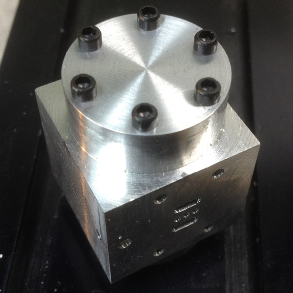
So, I went to a local machinists group meeting last weekend and took along a few of my bits and pieces. They were all very polite and seemed to be interested in what I was doing, without even scorning my table top machines. Anyway, at that meeting I realized that despite the near perfect fit between the cylinder heads and my bore, I would have to set them aside and make new ones. Why?, well I made them to fit a cylinder that was a few thou under target and wasn't finished. Yes, I know I could have used them and just let the engine settle in on its own, but the bore was tapered very slightly and I wanted a better finish before I ran it. Not enough spring cuts, I guess.

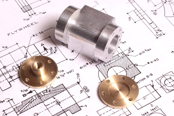
Cover your eyes now if you are squeemish. Not having any laps available, I decided a reamed bore would have to do. I loaded up the cylinder and .500 reamer with cutting oil and ran it through. That all worked out reasonably well but I now had two heads that no longer fit like I wanted. The outer end was no issue, but the inner end with the packing for the piston rod could be tough to locate accurately. Besides, I plan on painting this engine, and thought brass heads might look nice against the paint. The aluminum heads will get saved for something else I can finish out nicely slightly undersize.

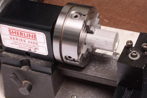
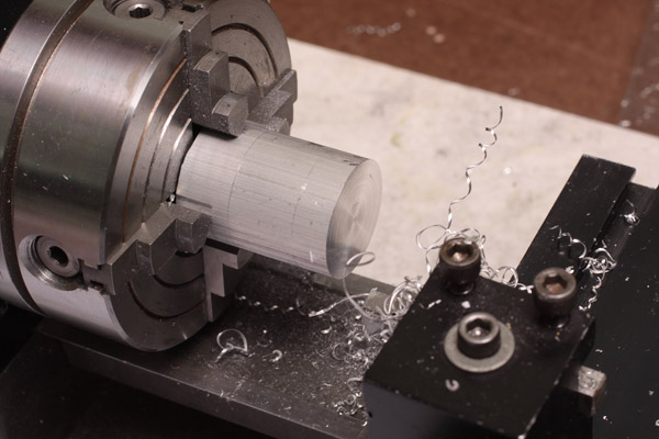
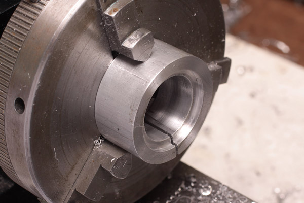
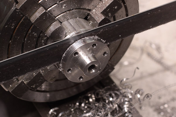
And now, back to the lathe. I didn't have any 1-inch brass stock so had to throw away a lot of some 1-1/4 that I have. It pained the cheap Scot in me - I was throwing away 58% of the material before I even got started after all. Working through my steps before cutting the blank I realized that the split bush meant I no longer needed a spigot for holding and I could use less than 3/4 of an inch of stock if I was careful, including the initial saw kerf.

head-blank-47863.jpg


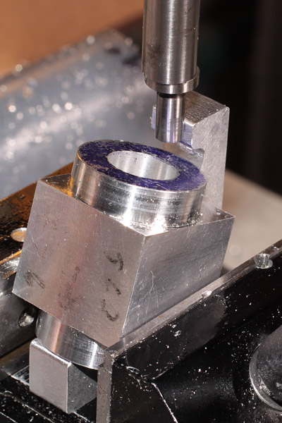
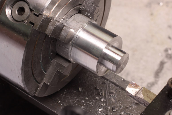
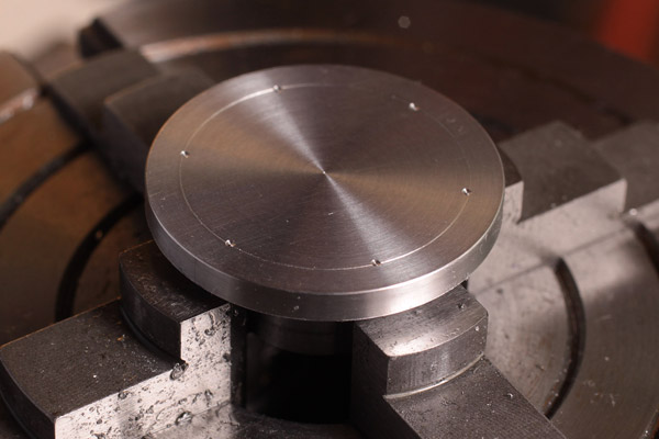
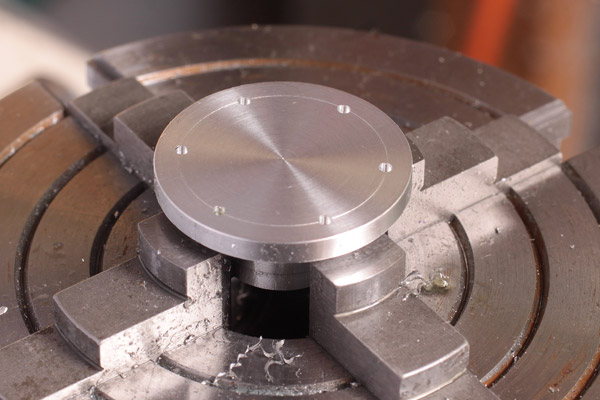
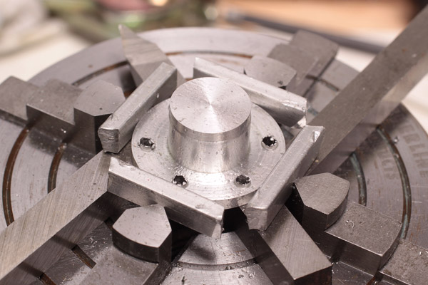
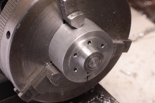
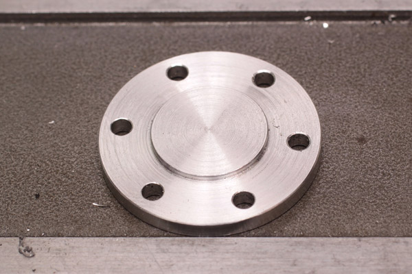
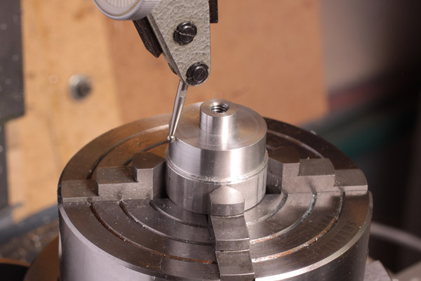
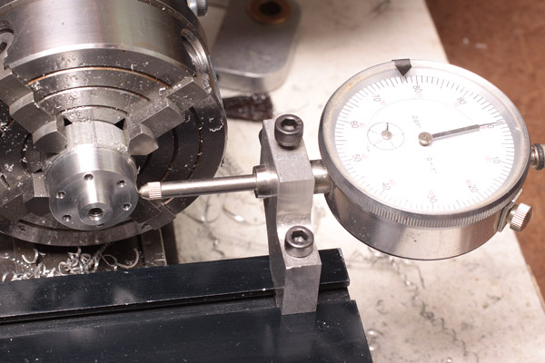
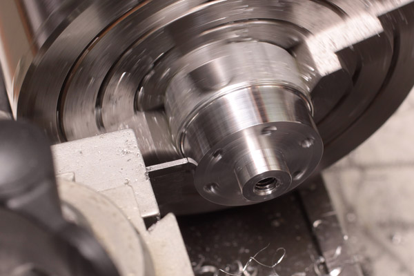
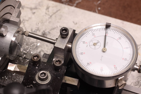
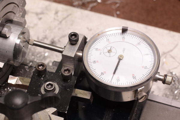
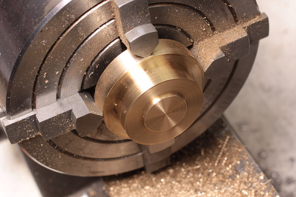
I didn't really take any photos since the process was essentially the same as before. First here is the outer blank turned to size with the small spigot to reference the bore. This fit is actually better than the original. From here I parted it off and mounted it up in the 4-jaw/split bushing combo, indicated it true and cleaned the outer face with a light skim cut. Notice in the second photo that I also created a slight recess. Why? I simply thought it looked better.

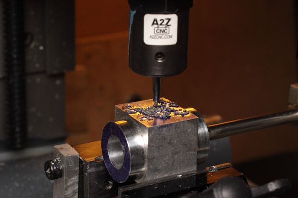
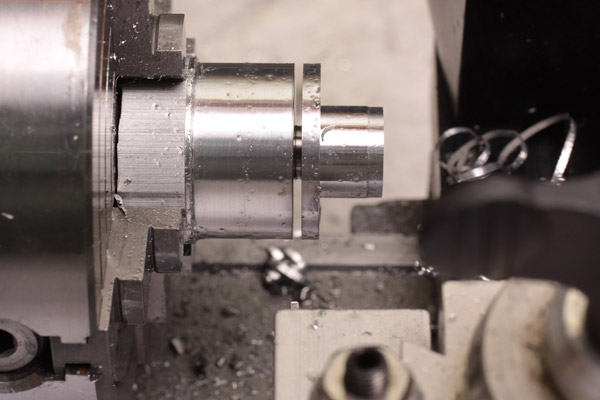
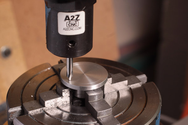
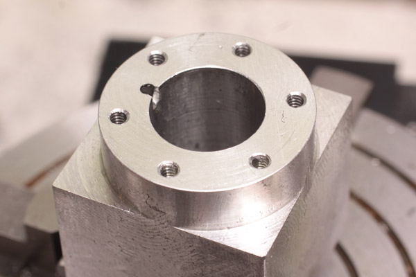
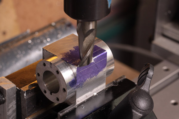
The inner head is the one that is critical. I did this by turning the spigot to receive the packnut, then drilled it for the piston rod, opened it up with the #21 tap drill and then tapped it 10-32 as indicated on the plans.

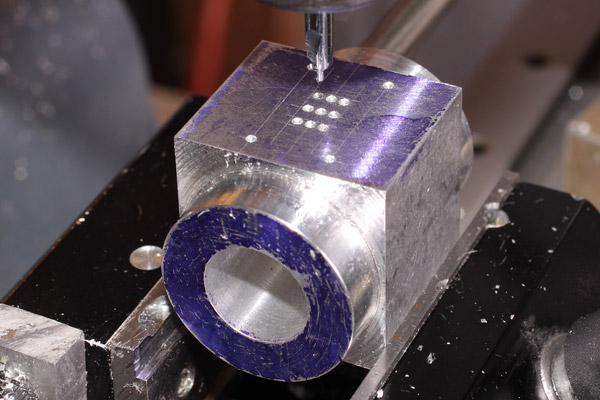
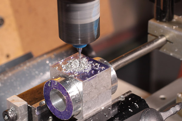
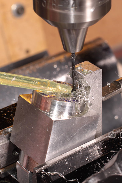
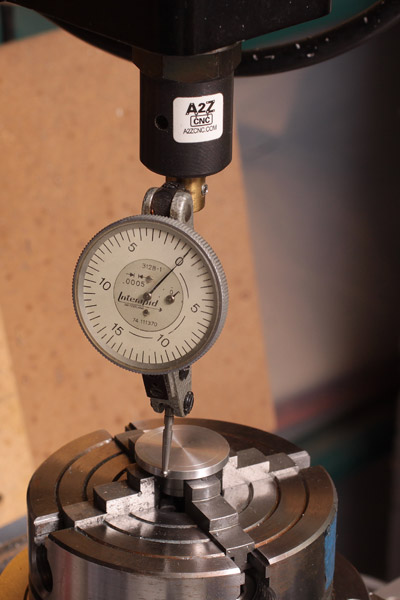
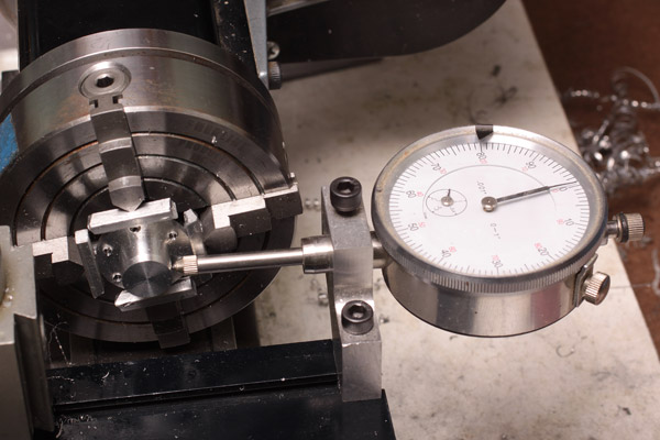
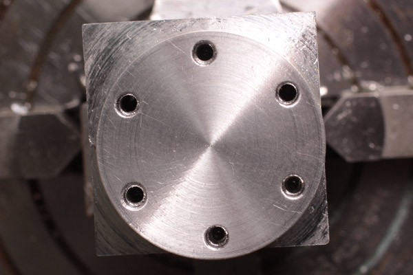
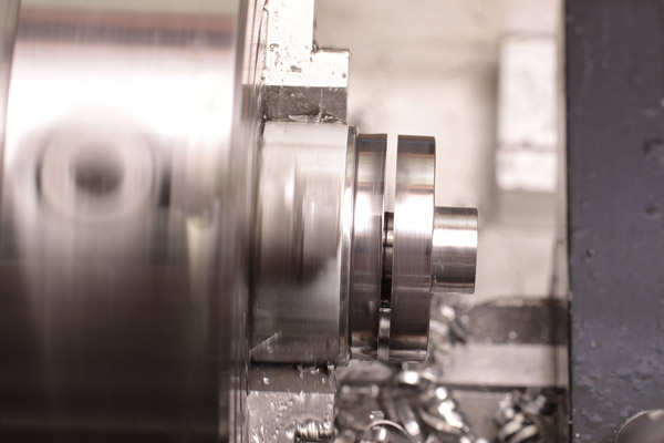
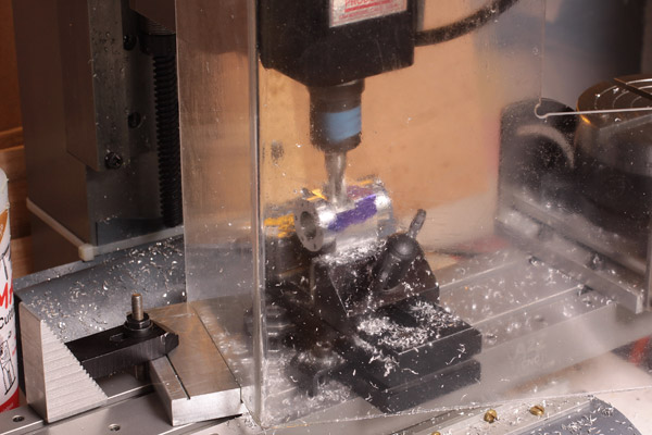
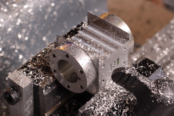
I then turned the rest of the OD before the chuck jaws down to match the cylinder head so I could reverse it and put it in the split bushing. After indicating it true I then milled the final thickness and bore spigot.

heads-47866.jpg


So now I have a little brass to polish on this and keep bright when I am done.
 
Last edited:

Latest posts

Back
Top