Well the photo processing went faster than I expected, quite the opposite of milling these parts!
No question, the bearing supports have been the largest single contributor to my scrap bin to date. You know that old saying "the third time is the charm"? Yeah, well that one fits somewhat, but not "to a T." This time it is more like "the fifth time is the charm," and even then I'm not completely happy with what I have. Despite the transient frustration though, I am still having fun. And in the end, that's really all that matters, right?
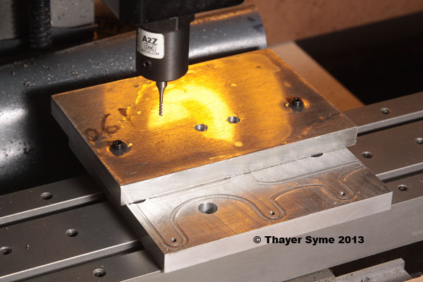
So let's get to the progress, such as it is. Just so you don't have to go looking back, here is what my setup looked like on my early attempts. Just a piece of plate stock secured to the tooling plate first used for the main bridge work. I was cooling and clearing chips with a mist bottle filled with denatured alcohol.
The problem with that approach was the mess that got left behind after milling awhile and the constant attention required. Not to mention the rate at which I was going through the denatured alcohol. The gray surface you see to the left does keep the chips off the y-axis ways, but they manage to get just about everywhere else.
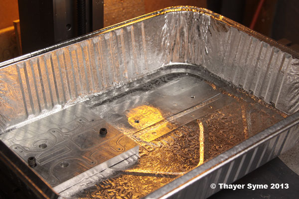
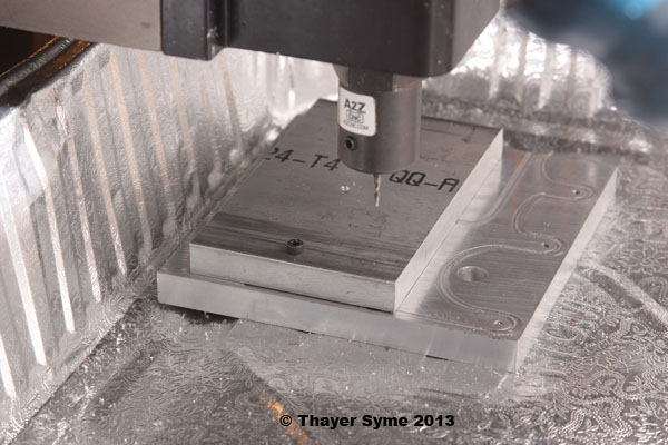
Milling the bearings takes right around two hours of machine time, so I decided to try an idea for cooling containment that I have been tossing around. I got a deep foil lasagna pan at the local grocery store and as you can see below burnished the pattern flat where my tooling plate would sit to help seal it between the tooling plate and table. I just used a pencil to poke a couple holes for the plate hold down screws. The plate is not yet secured in this photo, just resting in the pan.
I counted on a reasonable seal in the sandwich and in truth that seemed to play out as planned. When I removed the pan earlier this evening only the faintest amount of alcohol had weeped through to the table.
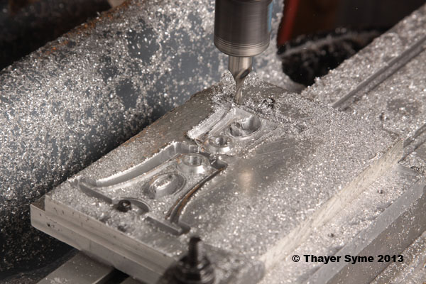
The milling sequence followed much as described previously, so I won't bore you with repeating that all. Below is a moment of great frustration though. Every once in a great while my y-axis stepper will make a gravely noise at start up and not respond, maybe once in every 50 or 60 power cycles. It has never faulted while running though, so I never thought much about it. That is, until I was 10-12 minutes from the end of my fourth attempt at milling the bearing supports a couple days ago. Things can go wrong with CNC pretty quickly. There was only something like 2 seconds between the failure and when I pressed the e-stop panic button. Regardless, that was still plenty long enough to cancel two hours of milling as the end mill drove through the lower flanges of the major bearing support.
I had hoped to salvage the minor support, but even that one was doomed on this attempt. My specified retaining tab thickness wasn't all it should have been and they flexed just enough to catch the part on the tool right before finishing. The resulting scars were motivation to scrap it as well.
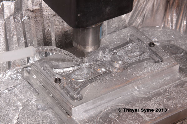
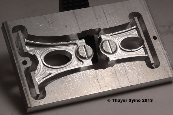
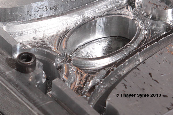
Here are the final few moments of the fifth round of cutting, this time with thicker tabs. You can see that I have now abandoned the mist bottle and rigged a rudimentary gravity-fed flood coolant system. A pencil hole in one corner of the pan transfers the used alcohol to one of a pair of plastic deli bowls that I am using to transfer it back to the source container. The system works well, and the constant attention required previously with the mist bottle has been reduced to only near constant. Yeah, a filtered transfer pump is on the shopping list. Any leads? Anything close to 1gpm flow should be fine.
Here are the parts still in the parent stock and you can likely see the problem in the lower end (right side) of the oval of the smaller support. The oval is not supposed to intersect the lower flange. A chunk of aluminum off-cut got caught against the tool and wedged it into the part. Drat!!!
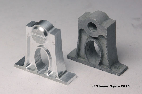
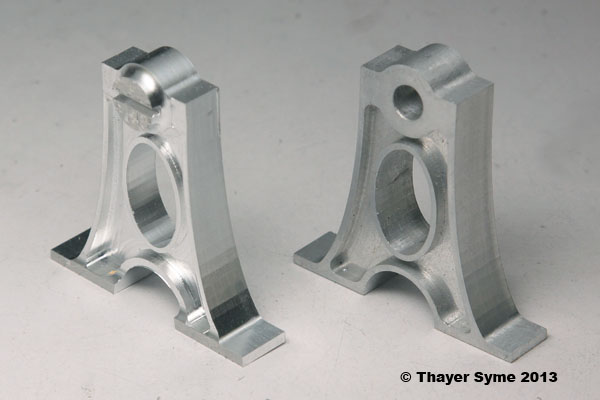
When I saw the first parts a month or so ago I felt they were too "blocky" and begged a bit more refinement. Here you can see how a slight taper helps out the minor support that is ultimately positioned on the raised base and supports the main shaft between the crank arm and eccentric. I decided to bore the bearing holes on the lathe faceplate, so did not drill them at all before milling. The horizontal slot lets me know how much stock to turn away, yet still gives me a reference surface coplanar with the foot so I can accurately secure it to the faceplate.
This view also shows off the scar at the base of the oval. I am considering milling out the offending area and having the oval be open instead of making a new part.
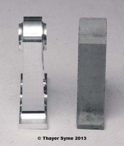
The side view shows off the tapering, as well as the radiused profile of the actual bearing area. Remember most of that will be milled off, leaving a more subtle contour. The support is not sitting flat as I have not yet cleaned all of the retaining tabs.
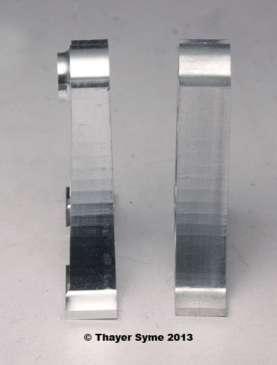
By comparison, here is the profile view of the major bearing supports with the redesigned part to the left and original to the right. As this support will sit outside the flywheel and not between two components like its smaller partner, I tapered it only on one side. Both supports will have the same head thickness when finished.
This is the show side that will be most visible once the engine is assembled.
Here you can see the back side that will be against the flywheel. The shallower pocket on this side is due to my centering the flange under the offset head. The dimple at bearing center is designed to help me align the support on the face plate for boring. The minor support has a similar dimple on its reverse side as well.
So there you have it. Six weeks or so of free time wrapped up in one good part and another I might still be able to salvage. And yes, I have laid in a supply of 2-56 taps. Hopefully one will be enough.