Elmer's #32 - Tall Vertical Open Column

Home Model Engine Machinist Forum

Help Support Home Model Engine Machinist Forum:

This site may earn a commission from merchant affiliate links, including eBay, Amazon, and others.
This is coming along great Arnold :bow:

I am a bit like Jan, making lots and lots of tiny things like nuts and bolts, to me, is really relaxing.

I don't think there are any shortcuts, it is just a matter of setting something up and going through each stage as required. I have some very small commercial threaded rod in stainless that I use for facing my nuts to size (that sounds painful), it can take the strain of the machining in such small sizes, whereas sometimes if normal steel is used, it is continually snapping off.
Making your own can be very advantageous, you can make smaller nuts with say a larger thread through them, to keep everything looking nice and neat when assembled.

Keep up the good work and we will soon be looking at another stunning engine from you.

John


Arnold, You're doing a fabulous job. Even making your own bolts and nuts.

I've often thought about it but it seems so time consuming. I suppose it would get quicker the more you do it and develop a system.

Not to detract from this thread but your tooling thread has given me so many ideas I don't know where to start.

Thanks so much for sharing. A "K" to ya.

Ron
 
Hi arnolb,

I have been following your expert build and have learned a lot. I just started the cylinder on Elmer's #29 and used your procedure. It has helped me a lot. Thanks for posting all the pictures.

Ed
 
Hi Ryan - I hope today's post will reveal the rest.

Thank you John :) I'm actually also starting to enjoy making the small bits - that is when I don't drop them ;) And I have to agree; there's no shortcuts; it all just takes a bit of effort. "... I use for facing my nuts to size (that sounds painful),..." :big:

Double thanks Ron :) I've made the nuts for nearly all my engines so far - simply because initially I couldn't buy them. As John mentioned, it can be useful to make one's own; I'm looking at my own work with an ever-more critical eye while building each engine, and I want things to look "right" - even though that is very subjective as different people's tastes differ. Thm: I'm glad you're enjoying the tooling thread as well. You'll notice I make up the bits of tooling as I need them - or in advance if I'll need them for a new project.

Thanks Ed :) I'm glad there's some useful information in my ramblings. Thanks for labeling my build as "expert" - but I am just an amateur and very much still learning as I'm going along.

More work on the nuts this afternoon...

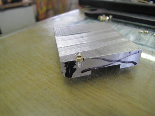
First up was a little jig to hold them for tapping; just a 2mm slot milled into a scrap bit of aluminium - to allow clearance for the tap, and widened to 3.4mm at the top to hold the nuts; I made them 3.4mm across flats:


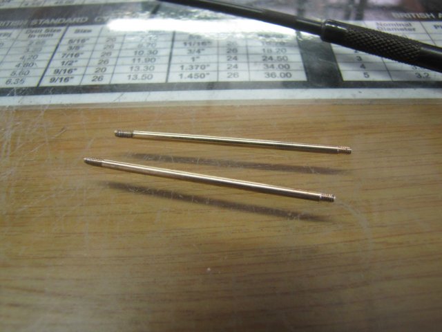
If you have a look at the previous set of photos I posted, you'll notice that all the nut blanks still have a little parting pip on them; that's about 1.7mm in diameter and fits nicely in the tap-groove in the jig. I had a hunch that the tap would also remove the pips when threading the nuts, and that actually worked. While tapping, the tap neatly removed the pip, and when unscrewing the nut from the tap, the bit just falls off:


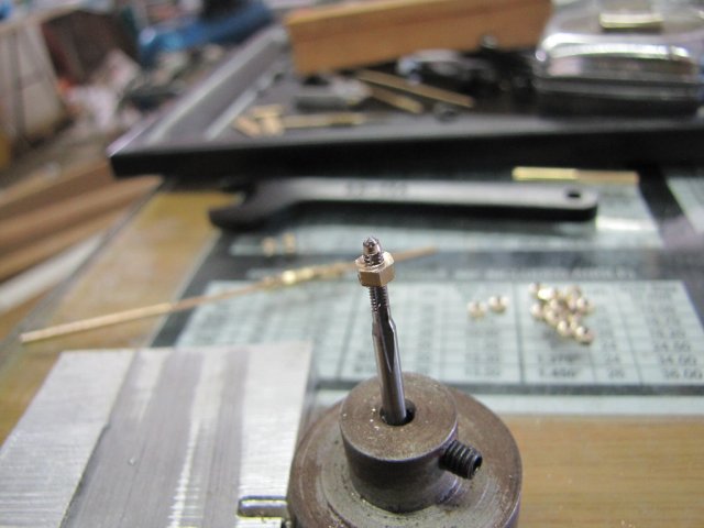
My "makeshift and ugly" tapping handle in the previous photo is really nice to use when tapping cylinder blocks and so on while using a tapping guide, but I found it a bit awkward for the nuts. Then I remembered I'd made a tapping handle for my M3 taps when I needed to get into a tight spot where the tap shanks were too short to use my regular tapping handle. The shanks on my set of M2 taps is the same thickness as that of the M3 taps, so I switched to that handle - it's much easier to use, and I'd made a convenient indentation on it's top to twirl against my index finger:
normal_IMG_4139.JPG

That made tapping really quick and easy; before a batch of fourteen nuts, I went to get a cup of coffee, and by the time I'd finished tapping all the nuts, the coffee had cooled just enough to be drinkable without scalding my mouth ;D

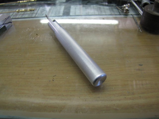
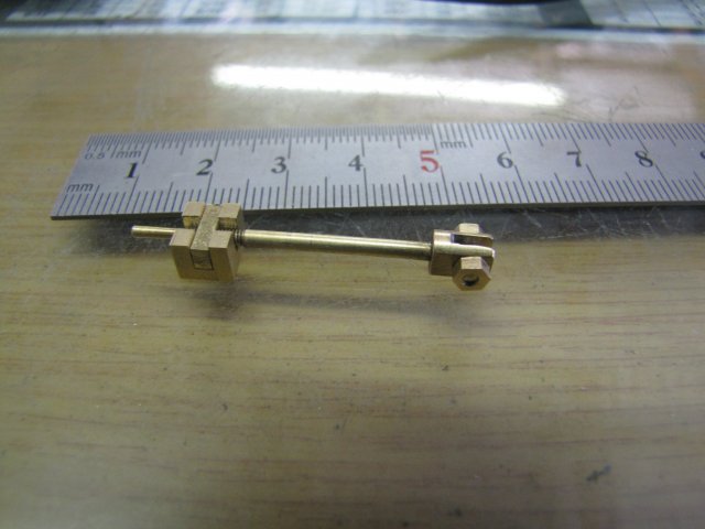
The nuts all still had some burrs on them from parting off; I just used a bit of threaded rod with a section of pipe to make a handle to hold onto them for cleaning up:
normal_IMG_4141.JPG


A quick lick with a file on each nut, then some emery, and a trip to the buff, and each nut was cleaned up in turn:


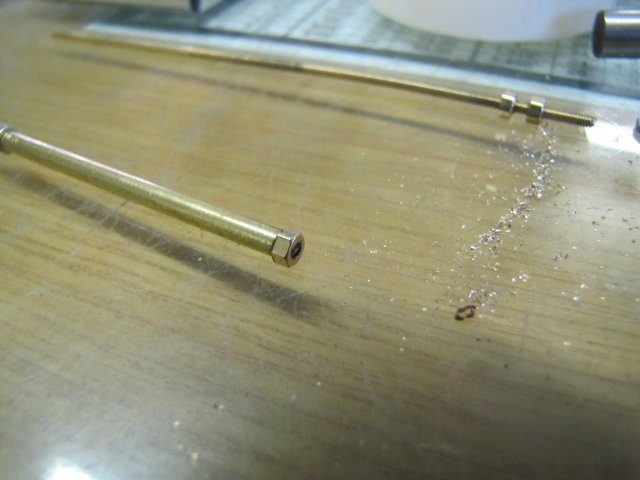
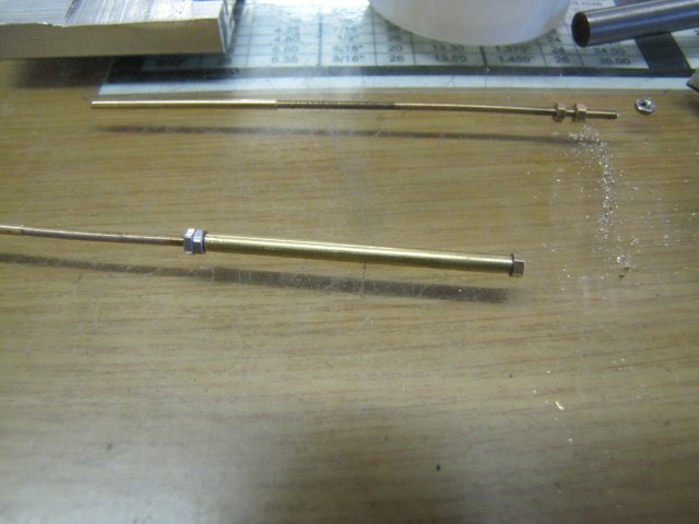
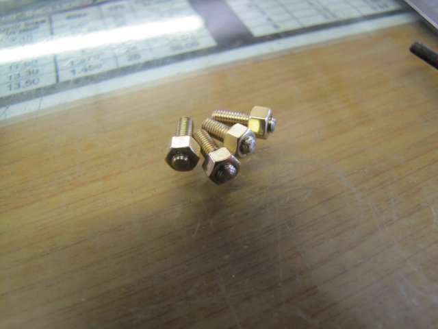
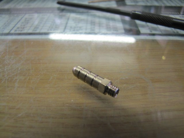
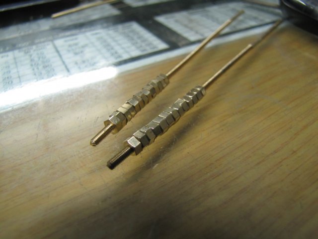
I ended up with a nice selection of nuts; screwed on threaded rod to prevent dropping them - the shop-monster must be starving, as I only dropped one nut for it to lunch on during the entire process:


The bits needed for the engine are getting less; I had a quick scan trough the plans and made a list, and what's left is the flywheel, steam connector, and I'd somehow slipped up making the valve and it's nut so far. The cylinder base mounting screws are also outstanding; I can't make up my mind whether I want to make those as studs 'n nuts or use dome nuts to match the column nuts...

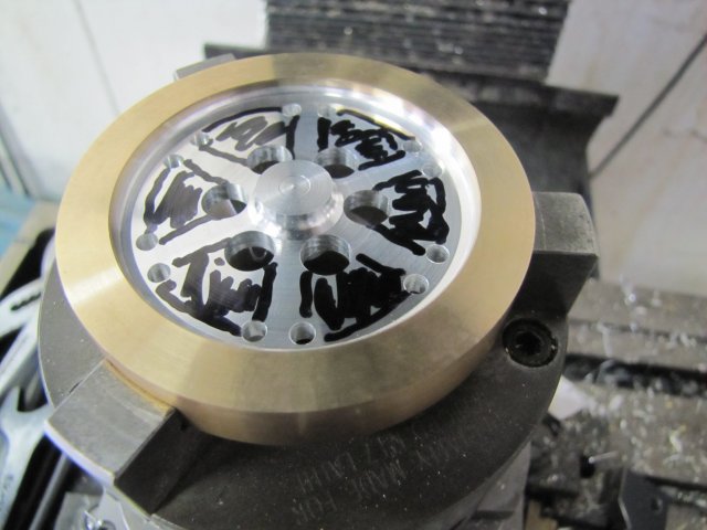
So back to the original intent of this build, and a try-out of the pocketing feature of the DRO while making the valve.
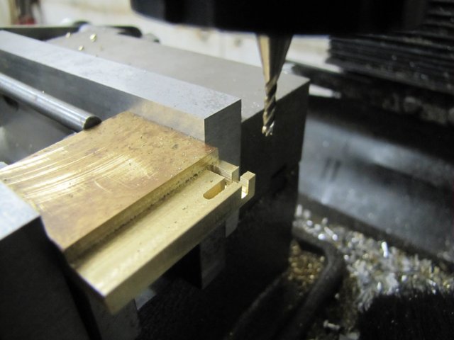
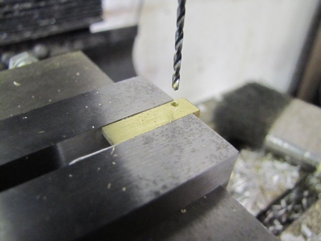
First off, I milled a bit of 8mm flat bar down to 5.16 mm on one side - that's the thickness of the valve - and then milled the slots for the valve nut and valve rod clearance; these are both 2mm wide - adapted a bit from Elmer's dimensions to match my valve rod and some 2mm plate I'll make the nut from:
normal_IMG_4143.JPG


Then I flipped the block, and milled the pocket using the DRO's feature. It's really easy to use; one enters the size of the milling bit, the center point of the pocket, and it's X and Y dimensions, and the DRO tells you to which positions to move while milling to hack out the pocket in a sort of square spiral fashion. What I found interesting was that it looks like the DRO software also compensates for the cutter thickness in terms of it's diameter while cutting; I used a 2mm cutter, and the coordinates were spaced to only take 1mm off each side, and amazingly, to conventional mill all the way ;D


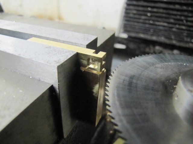
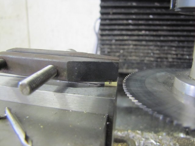
I then used a slitting saw to slit the valve off the parent stock:
normal_IMG_4145.JPG


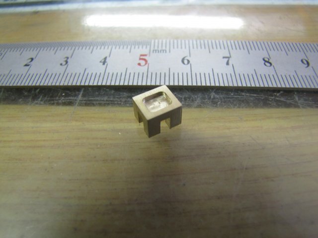
The completed valve, after a bit of clean-up work and flat-lapping the port face:

I'm not entirely happy with it; the one side looks like it's narrower - that's because of the chamfer on that side; I didn't notice that chamfer while machining the stock ::) The valve will work, as that chamfer is on the "side" and will not impact while in operation; if it was on one of the edges joined to that side, it would make setting the valve position very difficult... Maybe I'll just re-make it to get it spot-on.

Kind regards, Arnold
 
Had a bit more shop today - once it warmed up enough for me to stick my nose in there...

The first thing I did was to re-make the valve; this time round it came out better:
normal_IMG_4148.JPG


On to the valve nut, and I just used the DRO to locate the hole to tap-drill for M2:
normal_IMG_4149.JPG


After that I tapped the hole, and then used the slitting saw again to slit the valve nut from the parent stock. To prevent it flying off, I used a toolmaker's clamp to tighten down equally on both the parent stock and valve portion before the final slitting operation:
normal_IMG_4150.JPG


That pretty much completes the entire valve assembly:
normal_IMG_4152.JPG


I'd decided to go with studs for the cylinder base mounting, so I threaded up some 3mm brass rod, and made nuts from 3/16" hex rod (that was sold to me as 5mm ::) ). Feeling a bit lazy, I just locked the nuts to the studs with some thread retainer; I'll use them as "bolts" to mount the cylinder:
normal_IMG_4153.JPG


I quite like how the Kimble's flywheel turned out, and a similar one would go well with the brass/bronze/aluminium mixed theme of the engine, so I sliced off a section of bronze from the section of 78mm OD that I'd bought in December:
normal_IMG_4154.JPG


A 60mm diameter hunk of aluminium followed:
normal_IMG_4155.JPG


Then I cleaned up the rim and one face of the bronze:
normal_IMG_4156.JPG


The aluminium followed suit:
normal_IMG_4157.JPG


I had to resort to friction drive to clean up the rim of the aluminium - made that 59mm dead nuts:
normal_IMG_4158.JPG


The bronze had to be bored out for a press fit for the aluminium (58.96mm), but I'd run into the faces of the chuck jaws with the boring bar if I did that, so I used a technique John (Bogstandard) had shown somewhere and used three washers as spacers:
normal_IMG_4159.JPG

Once the bronze ring was chucked up, I just used the rule to push the washers out; they slid out easily. Can't leave them there, as they're liable to come flying out once the chuck spins up.

The rim hole was bored to size - and I made sure to add a small chamfer on the edge to help start the aluminium slug on it's way later on:
normal_IMG_4160.JPG


Then I plonked the aluminium bit in the freezer for about 20 minutes, and five minutes before fetching it I used a plumber's torch to heat up the bronze ring nice and hot. Then I fetched the aluminium bit - with a spare bit of ice stuck to it to keep it cold, and plonked it into the ring; a light tap with a small hammer sent it all the way into position:
normal_IMG_4161.JPG


A quick skim in the lathe, and I left things there to continue next weekend:
normal_IMG_4163.JPG


Regards, Arnold
 
Had a good shop session today; it would have been longer, but a friend I hadn't seen in a while dropped by this morning with a small problem I had to help him with... I got nice payment in the form of a slab of 76% cacao Swiss chocolate he bought in Europe a couple of weeks ago ;D

Work carried on on the flywheel. The spoke section was trepanned out first:
normal_IMG_4165.JPG


Then I played around with Marv's flywheel generation program, and ended up with this lot - I just added the metric measurements to make life easier for me in the shop:
Code:
***** NEAREST INTEGRAL ANGLE SOLUTION *****

Number of spokes = 6
Radius on which inner holes are located (R1) = 0.472 in   12mm
Radius on which outer holes are located (R2) = 0.984 in   25mm
Diameter of inner holes (2*r1) = 0.315 in   8mm
Diameter of outer holes (2*r2) = 0.157 in   4mm
Distance from spoke CL to outer hole center (d2) = 0.137 in 3.5mm

Angle from spoke CL to inner hole center (theta1) = 30.000 deg
Angle from spoke CL to outer hole center (theta2) = 8.000 deg
Angle btw two outer holes in same web space = 44.000 deg
Inner spoke width = 0.157 in  3.99mm
Outer spoke width = 0.117 in  2.97mm
Minimum radial web length (W) = 0.748 in 19mm

Assuming that a spoke CL is initially aligned with the mill y axis,
the rotary table must be rotated (phi=) 2.000 deg to bring the spoke edge
parallel to the mill y axis.
The table must then be offset by (x=) 0.092 in plus half the cutter diameter. -> 2.34mm + 2mm = 4.34mm

The rotary table settings (deg) for the inner holes are:
30.000
90.000
150.000
210.000
270.000
330.000

The rotary table settings (deg) for the outer holes are:
8.000
52.000
68.000
112.000
128.000
172.000
188.000
232.000
248.000
292.000
308.000
352.000

I started drilling holes according to the print-out; the bigger holes around the rim was drilled 8mm final size - taking care to get as smooth a finish as I could from the drill, and the outer ones 3.5mm - as I'd be using a 4mm end mill to make all the cuts. I like to do this, as it leaves a bit of meat to first rough out things and then take a final light pass to full size to get a better finish:
normal_IMG_4166.JPG


To help prevent a brain-fart, I used a marker to join up the holes and mark the sections that will come out; it's a simple, but convenient way to eyeball things while going along:
normal_IMG_4167.JPG


For the rough cuts, I also jotted down some new angles on the flywheel sheet - so that all the roughing could be done slightly under-size:
normal_IMG_4170.JPG


Then I milled out the curved sections - first with the rough machining to the jotted down angles above and leaving 0.3mm on the web diameter for clean-up. It was a pretty brutal - just 2 passes per curve to take the 4mm cutter through the web. Then a finish pass through all the curves to the original calculated angles and final web diameter with the cutter at full depth for that pass. In the next photo you can see on the "inside" of the curves how crude the rough pass was, compared to the nice smooth sections on the outside where it was done to finish:
normal_IMG_4169.JPG


Next I started milling out the spoke sides - also with a rough pass first to hog things out just below size, followed by a finishing pass:
normal_IMG_4171.JPG


Five hours later, and all the spokes milled out - with a glaring mistake on the third final pass spoke...:

::) I'd run the cutter in too deep toward the hub; after long concentration my mind was wandering...
The over-run should blend in OK with a file though; it looks worse on the photo than what it really is, as it has a burr standing up that's fooling the eye a bit.

I was hoping to finish the engine this weekend, but I don't think it will be done; The flywheel needs its final touches, there's still a couple of bits to make, and all the parts need to be stripped down for a final clean-up.

Kind regards, Arnold
 
I love the flywheel Arnold!
 
Arnold (and others who may use the program),

The only thing in this program that makes it Inferial is the fact that dimensions are labeled as inches. Since no internal unit conversions are done, one can directly enter (consistent) metric units and interpret the outputs (labeled as inches) as whatever metric units were input.

To demonstrate what I'm talking about, in the example below wherever the program asked for inch inputs I entered the millimeter values from your example above. Note that the calculated spoke widths and web length values, although labeled inches, correspond with your metric values.


Code:
Number of spokes = 6
Radius on which inner holes are located (R1) = 12.000 in
Radius on which outer holes are located (R2) = 25.000 in
Diameter of inner holes (2*r1) = 8.000 in
Diameter of outer holes (2*r2) = 4.000 in
Distance from spoke CL to outer hole center (d2) = 3.500 in

Angle from spoke CL to inner hole center (theta1) = 30.000 deg
Angle from spoke CL to outer hole center (theta2) = 8.048 deg
Angle btw two outer holes in same web space = 43.904 deg
Inner spoke width = 4.000 in
Outer spoke width = 3.000 in
Minimum radial web length (W) = 19.000 in

Assuming that a spoke CL is initially aligned with the mill y axis,
the rotary table must be rotated (phi=) 2.000 deg to bring the spoke edge
parallel to the mill y axis.
The table must then be offset by (x=) 2.359 in plus half the cutter diameter.


This technique can be used with many of my programs (and other folks' programs). Be careful, though. It will only work if the program does no internal units manipulations.
 
Flywheel making seems to be an art on its own, wether you use the mill or saw and file it takes a long time. Rounding the spokes is a bit of a nightmare ;D This must be the one part of an engine where a casting is hard to beat. An alloy hub with a dense rim is a good way to go, my last flywheel was from solid steel and was a pain in the fingers :big:
 
Thanks Brian :)

Marv, Thank you :bow: ; I actually suspected as much, but didn't want to take a chance...

Thanks Jan; :) - yes, flywheel making does seem to be an endeavor of it's own... I'm not even going to attempt to round the spokes on this one; this build has already taken more time than I anticipated :big:

Had a good session in the shop today ;D

The flywheel was drilled and reamed out for a 6mm axle, and then I clamped up the dividing head at a suitable angle in the mill vise - not to be used for dividing, but purely as a convenient way to hold the flywheel to drill for the grub (set) screw. I first used a center-cutting mill to drill down a bit to allow the M3 tapping drill to start without wandering:


After drilling the 2.5mm hole through, I tapped it M3. That little straight-shanked ER11 collet chuck I turned up is proving to be extremely useful all round - here I just used it to chuck up the tap, and let it slide in the Mill's collet chuck as tapping guide:


Clean-up followed. The bronze ring on the flywheel proved to be a real b@st@rd to get a nice finish on... I eventually gave up and left it at this:


Actually the photo makes it look worse than it is. From a bit further away with a quick try-out on the partly assembled engine, it looks slightly better:


Some 2mm bronze brazing rod volunteered to be threaded on both ends - these are to mount the cross-head arms to the columns:
normal_IMG_4177.JPG


The steam/air adapter was a quick job:
normal_IMG_4178.JPG


At that point I ran out of bits to make :eek:

So, I disassembled everything, except for the bearing columns:


All the parts got a final once-over; there were still some tooling marks on the bearing columns that were removed with emery, and the "shiny" bits got a final run past the buffing wheel.

Then everything jumped back together again in slow motion - and after a solid hour of careful re-assembly, I ended up with an engine. The photos are not that great, as I don't have a nice setup with adequate lighting :-[


Does it run ?.... You Betcha ;D ;D

I didn't mess around too much with setting the timing. Before fitting the steam chest cover, I set the valve to slightly favour the bottom part of the cylinder as the connecting rod assembly isn't very well balanced, so a bit more power on the up-stroke and gravity helps a bit with the down-stroke. The slip-eccentric was just set to have the grub screw in line with the "pointy" bit of the crank. The engine runs slightly better in one direction than the other, so the eccentric still needs a bit of adjustment.
During assembly I tested each and every moving part for minimum friction. The packing nuts each had a bit of plumber's PTFE tape rolled up and coiled around the valve and piston rods with the nuts snugged down on that, and then loosened up slightly to get free movement.

OK, enough rambling; this video really is the engine's first run on air - without any fine tuning or running in. I'm a happy chappy ;D:
[ame]http://www.youtube.com/watch?v=b06vloxS7oQ[/ame]

This was a really fun build - if I re-read my starting post, things seemed to have mushroomed along the way, but maybe that's a good thing. Not only did I get to simple grips with the DRO, but I fairly successfully tested a couple of new-to-me techniques along the way and added a very handy bit of tooling to my steadily growing shop.

Many thanks to everyone who followed along and added voices of support, advice and inspiration :bow:

Kind regards, Arnold
 
I just read your thread Arnold and you have made it into a fun built. I really enjoyed reading it and super job on the Elmer #32. That is one beautiful engine and a must on my list to do. Thanks for sharing.
Don
 
Congrats Arnold! It's got a great sound Thm:
 
It's a nice looking engine with those links. Love an engine that runs on next to no pressure. Enjoyed following along and learned a heap, thanks for the trip.

Jan
 
Oh that's a sweet one Arnold!
Nicely done!


:bow:
Dave
 
Really great build Arnold - enjoyed this thread from start to finish and as per usual picked up a few tips along the way.

Great looking & running engine.

Regards,
Ken
 
Great Job Arnold you got a real fine finish on it and it runs very well

Regards

Stew
 
Thanks Arnold for the detailed build notes and great photos. A sweet runner.

Vince
 
Many thanks Gents for your positive replies :bow:

Time to sort out my shop a bit to make space for the T+C grinder that will be arriving in the next couple of weeks, and thoroughly service all the machines. I haven't selected my next project yet, but I'm really feeling in the mood for a live steam project, so things might just go that way. And I have a favour to do for a friend as well :)

Kind regards, Arnold
 
Another excellent build Arnold.

And so many useful techniques to learn from :)

Clive
 
Back
Top