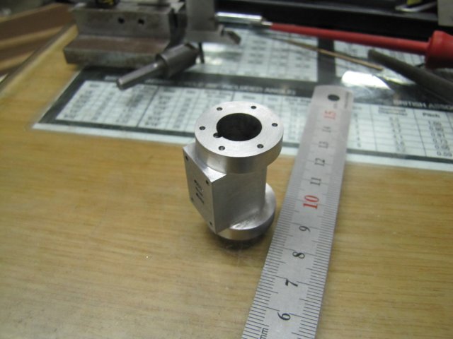
Elmer's #32 - Tall Vertical Open Column

Home Model Engine Machinist Forum

Help Support Home Model Engine Machinist Forum:

This site may earn a commission from merchant affiliate links, including eBay, Amazon, and others.

arnoldb

Well-Known Member
Joined
Apr 8, 2009
Messages
1,792
Reaction score
12
Having fitted the DRO to my mill, I looked through my list for a project to try it out and get to grips with it. Even though I have an itch to build a complex and detailed engine, I thought something fairly simple would be better to try out the DRO to get the gist of working with it.

One of Elmer's would do. The collection of engines on my side-board are growing, but there's a lack of height there, so I settled on Elmer's #32 as a relatively simple engine (compared to the Kimble and Coombers) that has a fair amount of work that can be done on the mill, as well as adding some height to the collection.

I'm not going to go overboard on this build; for the most part I'm going to build it exactly to plans. One exception will be that I'm going to add a slip-eccentric to make it reversible, as this is very easy to add to this engine as a custom touch.

Don't expect too many photos, but if there are any members that would like more detail on certain bits or processes of the build, please ask (publicly, or pop me a personal message), and I'll be happy to accommodate. Any suggestions or criticism is also welcome :)

I started off with sawing a 78x78x12mm bit of aluminium from a sheet of 12mm plate I have. That was roughly squared up, and then I brought out a bit of kit I have that I've used rarely before - the venerable edge finder. Mine is of slightly dubious quality, and I've never really bothered to set up test equipment on the mill to check it's accuracy and repeatability. Another disadvantage that I had with the edge finder is that it is 5mm in diameter, and my mill's feed screws are 3mm per turn, meaning that in the past I had to be careful about finding an edge and setting the zero-able hand wheel dials correctly to obtain my datum point. So first things first, I tested the edge finder - and much to my surprise it ended up repeatable within 0.005mm (1/5 of a thou) in four out of five tests :eek: - that's much better than I expected, and plenty good enough for my shop; 0.01mm repeatability would be fine with me. With the DRO, backlash becomes a lot less important, and it's easy to set absolute zero.

Next I put the DRO to test; I located the right-hand back edge of the workpiece; I tend to work from the right-hand side of the vise as that way I end up with the least amount of chips thrown toward myself while milling, and the fixed end of the vise jaw remains in position on the Y axis. The block of aluminium plate was then properly squared up to size, with the aid of the vise stop.

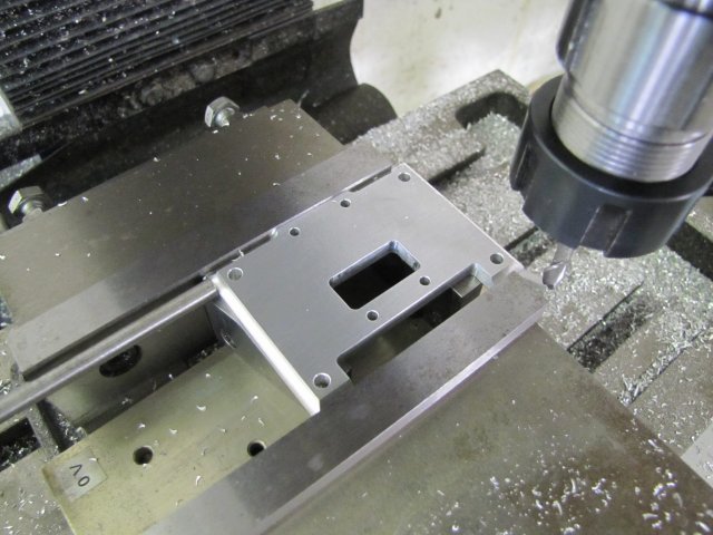
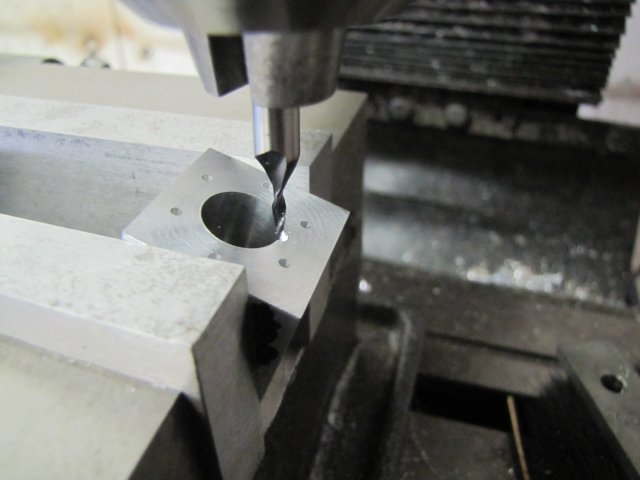
For the next step, I didn't lay out anything; I simply coordinate drilled four 3mm clearance holes and the small square's 2.5mm tapping holes for M3 using the DRO and incremental readings:
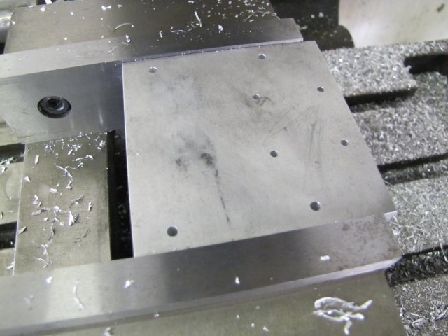
normal_IMG_3846.JPG


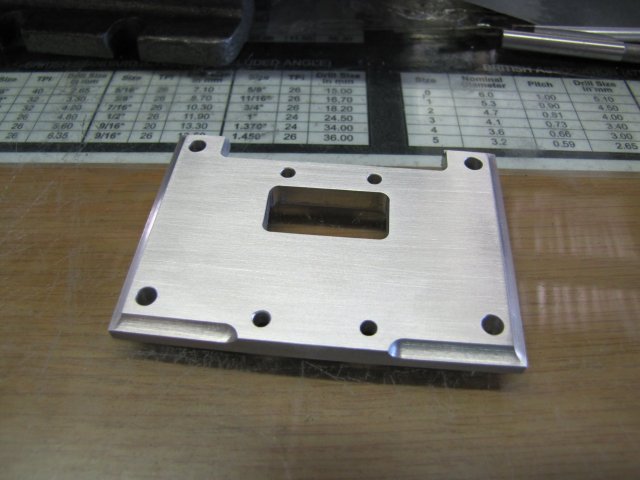
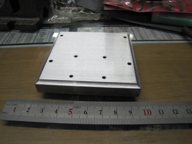
After a bit of decorative milling with a 6mm ball nose mill, tapping the M3 holes where the cylinder will mount, and a bit of elbow grease with riffler files and emery paper to get rid of toolmarks, the base was done with a brushed finish:

We have a long weekend coming up here in Namibia, so I'm going to try and give the engine a good go, but I might divert a bit to attend to a special request I received from a South African member.

Kind regards, Arnold
 
That base looks fantastic arnold!! I suspect you will become addicted to that DRO rather quickly and then wonder what you ever did without it :)

Regards,
Bill
 
This will be fun to watch. I'll be along for the ride.

Congrats on the DRO. I would hate to be without one now.
 
OOOO! OOOO! Another one coming out of the barn from Arnold. I can't wait. This should be another good one to watch. Have a safe holiday Arnold.

BC1
Jim
 
My next planned build is Elmer's #32 so will be watching with interest.
 
Bill, thanks :) - I'm already in love with the DRO ;D; it makes life a lot easier.

Thanks Brian :) I hope the ride will be worthwhile.

Thank you Jim :) Safety's always a main concern; I'm going to stay put and work in the shop ;D. Safe as barns, as long as I don't stick my fingers where they shouldn't go or have a mid-life moment. I'm much too young for a senior moment :big:

Jan, thanks for checking in :). If you want more detail on any specific bits of the build, just give a shout.

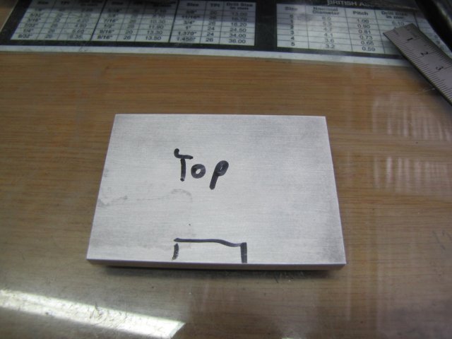
On to the table. I scrounged up a bit of 6mm aluminium plate for that. It had a couple of dings in it, so I gave it a quick rub-down with Scotch Brite on both sides, and chose the best-looking side for the top. There's only one deepish ding on this side, so I juggled things so that it would get hidden by one of the bearing columns, and just used a permanent marker to mark things out as a reference:
normal_IMG_3850.JPG

The ding is the black spot above the rectangular ink lines for the cut-out.

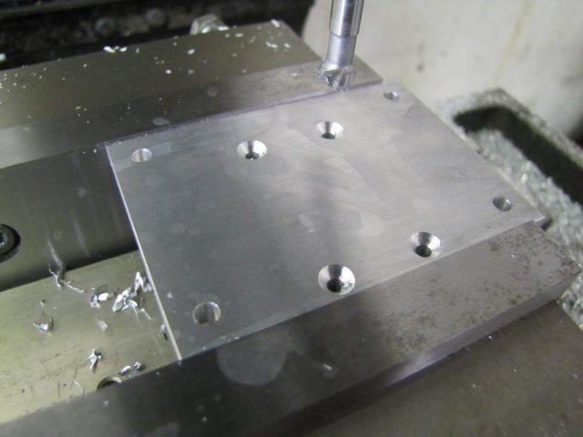
I milled the plate to size, and from the underside drilled all the mounting holes. The ones for the bearing mountings were countersunk as well:
normal_IMG_3851.JPG


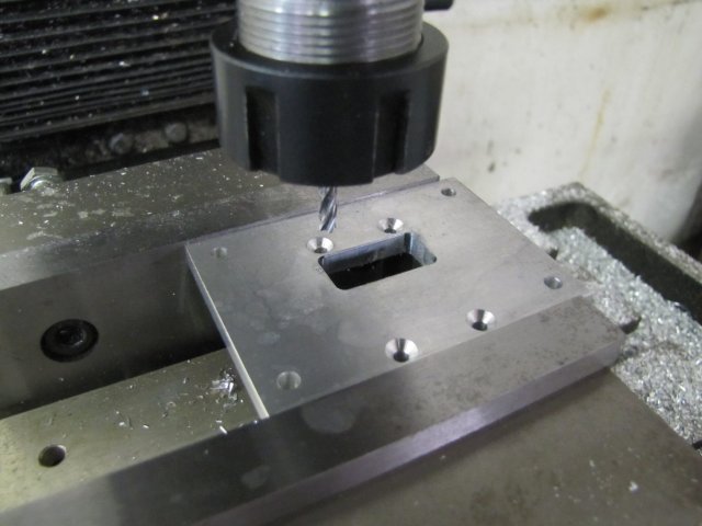
Next I milled out the hole for the eccentric rod. Now this is where the DRO really is nice to use, as I could get the readings straight off the display. Compensating for backlash was always a problem in the past. Here it was easy to just center the DRO on incremental setting and mill out the pocket 0.2mm under-size on all sides, and follow that with a full-depth clean-up pass on all sides to remove the last bit. That left a very nice finish and a pocket very nicely to size:
normal_IMG_3852.JPG


Clearance for the connecting rod was easily dealt with:
normal_IMG_3853.JPG


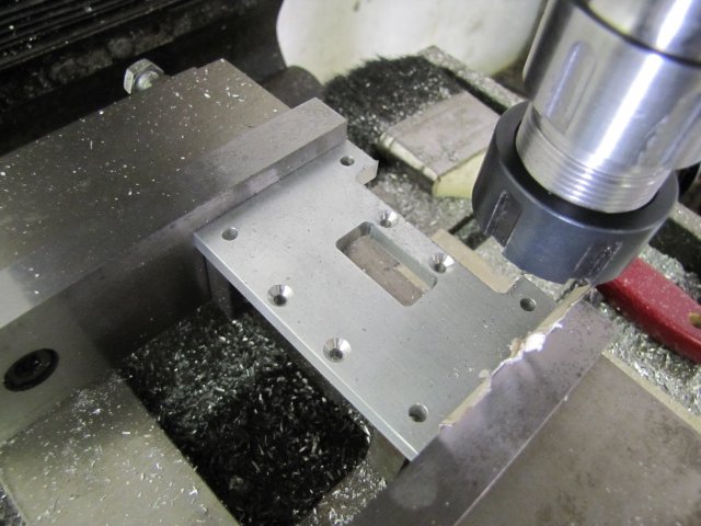
The plans don't call for it on the table, but I decided to add matching decorative work for the base to it. As the bearing blocks will be on the edges, I had to compensate for that, but that was easily done:
normal_IMG_3854.JPG


After a bit more manual elbow grease, the table was done:

::) Really not much to show for 3 hours' work...

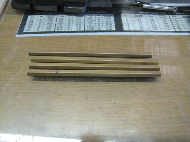
For the columns, I went with some hex brass. I bought it as 6mm hex, but it measures out at 6.2mm across flats. So it's not really 6mm, and neither is it 1/4" (6.35mm) ::) - at least I got a bit more than originally bargained for :big::
normal_IMG_3857.JPG


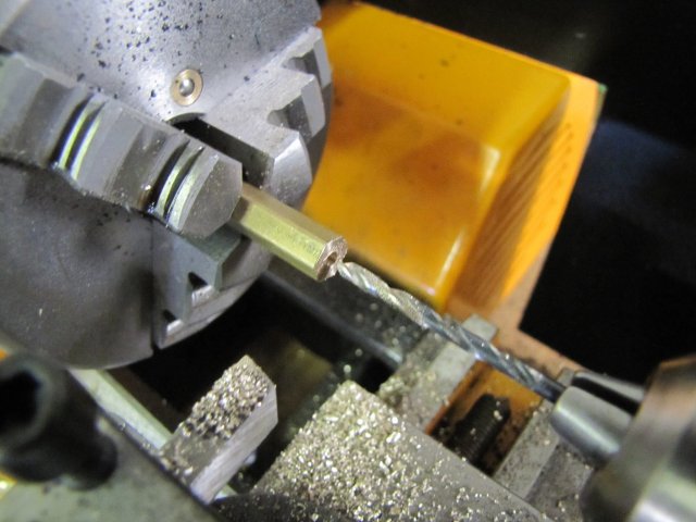
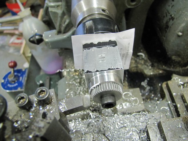
My small lathe is still not properly mounted, but it's 3-jaw chuck has a lot less run-out than the Myford's one. As the work required on the columns is light, I fired up the small lathe, and started facing the columns and drilled for M3 threading:
normal_IMG_3858.JPG


I've never pulled my finger from you-know-where to make backstops for either lathe, so I fell back to clearly marking out the lengths for the sections on the columns and turning down to "split the line" by eye. No photos of that.

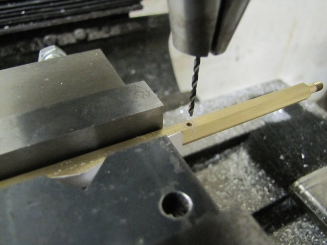
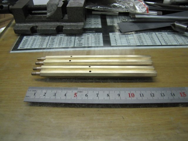
The holes for the pivot pins in the columns was easily dealt with, though I did fall back to using good old marking out, the vise back stop, and eyeball mk1 for repeatability on the X axis. There's four different operations for each of the columns; one had to be drilled 1.6mm (not through) and tapped (M2 in my case after bastardizing Elmer's plans to metric) - and a matching 2mm through hole in a second column. Then on the next pair of columns, the same happens; a 2mm thread, and a 2mm through-hole - but at a different distance from the bottom of the columns.
In a scenario like this where I need to drill smaller blind holes and then larger through-holes, I always do the small blind holes first. If I make a booboo and drill the small hole through in a moment of inattention, I can always enlarge it, and try the blind hole on the second workpiece. Here I'd just drilled the 1.6mm blind hole for tapping to M2 in the first column:
normal_IMG_3859.JPG


All the holes drilled and tapped in the columns, and a bit of clean-up later, the columns were done:

::) From the enlarged photo, I see I missed a couple of spots with the clean-up, and got some angles skewed on the rub. I'll sort those out at final assembly.

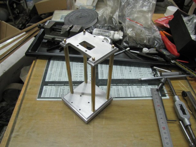
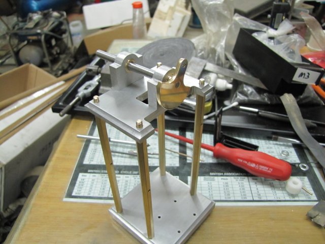
With one of the swarf magnets repeatedly digging his paws into my leg and running out the shop to his stainless steel food bowl and loudly bashing that around, it was time to shut shop and feed the dogs. I took a quick assembly shot showing overall progress:

Please excuse all the clutter :hDe:. I think I need to take about 1.5mm off each of the threaded sections of the columns, as these are standing a bit too tall. I need to make up acorn nuts to fit on top, and I don't want those out of proportion.

Regards, Arnold
 
Looking good Arnold. Will be following your progress. Thanks for taking the time to post your work. Roger
 
I like the idea of the hex columns, adds a bit of visual interest as does the extra machining on the table. Look forward to the next instalment.

Jan
 
John, Roger & Jan, thanks very much Gents :)

Some of the "simple" parts in engine builds can take the most time to make...

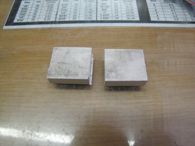
I started today's session with two blocks of 8mm aluminium plate for the bearing blocks:
normal_IMG_3865.JPG


Those were glued together with one reference side in common, and finished to size together. Then I drilled a 10mm hole through them to insert bushes later for the crank shaft, and finally I drilled the mounting holes to tap M3:
normal_IMG_3866.JPG

The "uneven" look between the two pieces you see there is because this was the reference side I used initially for gluing them together. When I drilled the hole for mounting the bushes, I'd also brought the vise backstop op to the workpiece; this allowed me to just position them vertically and maintain the X setting on the DRO for the center.

On to what I've personally come to call "Elmer's Folly" ;D - the "fake" bearing shells. I had actually considered making real split bearings, but decided against that for this build - that can wait for a future highly detailed build. On some of my Elmer's engines I actually completely skipped the faux bearing cap structure, but on this one I decided to add it, so I set about milling them out:
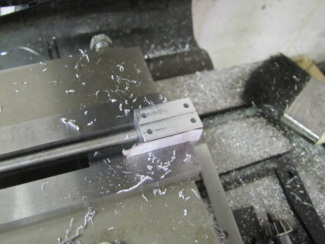
normal_IMG_3867.JPG


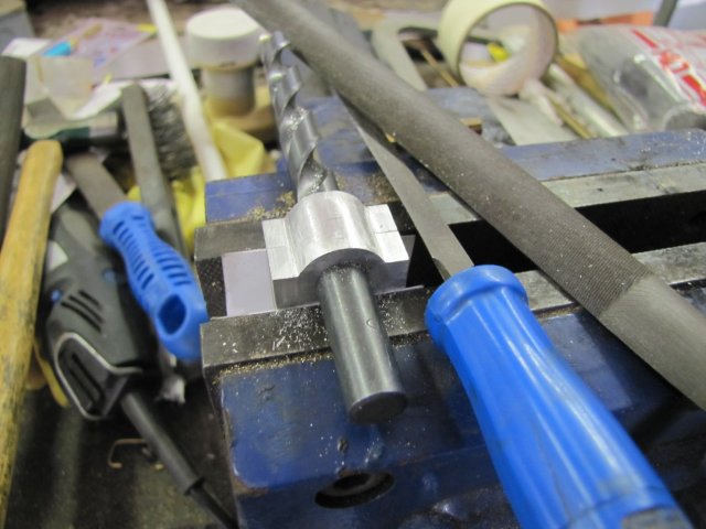
A bit of filing got rid of the facets left after milling the tops:
normal_IMG_3868.JPG


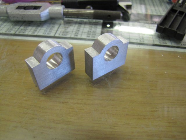
Then I split the pieces, and spent some time to get their finish to match that of the table and base- keeping the "brush grain" in the same direction:
normal_IMG_3869.JPG


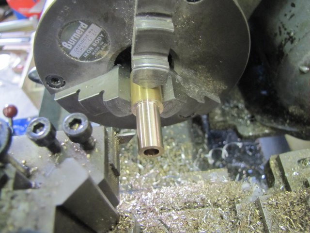
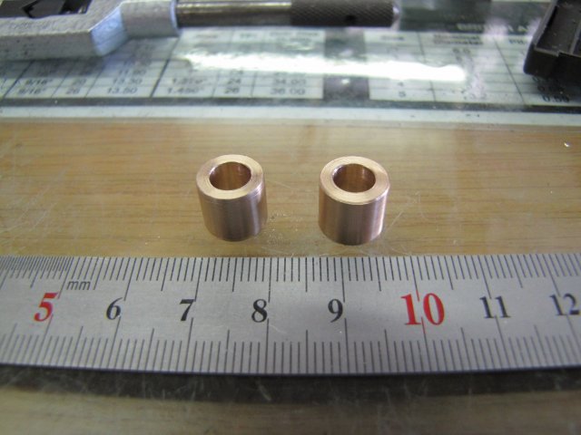
On to the bushes - a bit of phosphor bronze drilled 5.9mm and then for a press fit on the OD for the holes in the bearing blocks. Getting ready to part off the first bush:
normal_IMG_3870.JPG


The two bushes done:
normal_IMG_3871.JPG


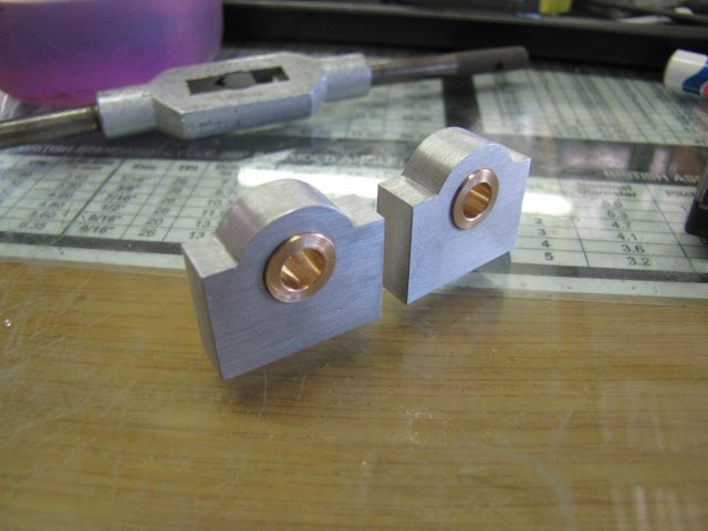
And pressed into the bearing blocks:
normal_IMG_3872.JPG

The little bit the bushes stands out from bearing blocks is intentional. On many of Elmer's engines he has other bits - often time the eccentric - running directly against the bearing blocks. I'm not too keen on that, as it can add quite a bit of friction especially on painted engines. This is my way to get things away from the bearing blocks. On this engine, the eccentric would run against the bearing block if built to plans. Of course, one can just turn up a very thin spacer to prevent that as well, but it's much harder to turn up thin washers than it is to just make the bushes a bit longer. One downside of doing as I did, is that your finish on the bearing blocks must be done; it's darn hard finishing up things around a sticky-outy-bit.

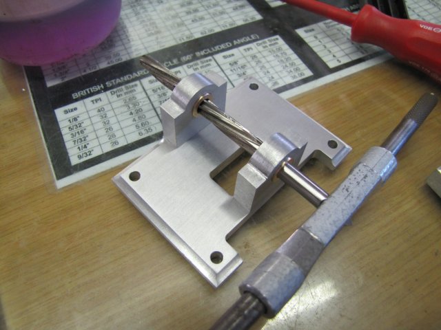
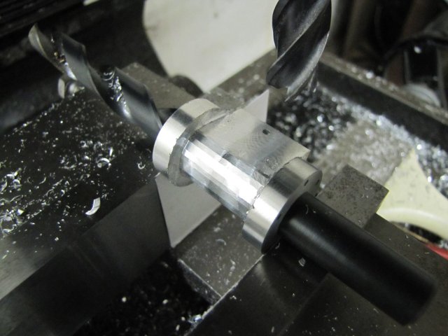
Finally, I marked each bearing block for it's location and orientation on the bottom, and screwed them to the table. Then I used a 6mm hand reamer to line-ream them:
normal_IMG_3873.JPG

Reaming was done from both sides as the reamer is just long enough to do the job. I've found that reaming from both sides for this type of scenario helps a lot, as the holes end up just slightly over size, which is nice to get a running fit. I don't have any over or under size reamers.

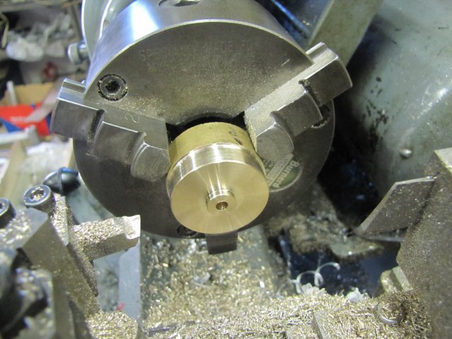
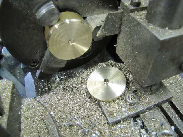
On to the crank web. I have a suitable size of aluminium bronze floating around that I got a couple of years ago - mistaking it for brass. I had other ideas for it back then, but I didn't know that it is hard to solder or silver solder - that I only learnt here on HMEM, but for this job it's fine. SO I set about turning it down a bit - it actually machines quite nicely:
normal_IMG_3874.JPG


Normally I'd get the chuck to the mill and onto the rotary table at this point for the next operations, but today I decided to use a different route. Parting off the ~34mm disc was a breeze as well:
normal_IMG_3875.JPG


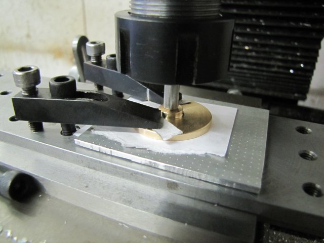
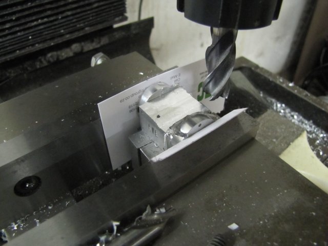
I just plonked the tooling plate on the mill, and with a bit of 6mm rod with an accurate conical point pressed the disc to the plate - with some sacrificial plate and pieces of paper to add friction wedged in between. Then I just clamped it down, and zeroed up:
normal_IMG_3876.JPG


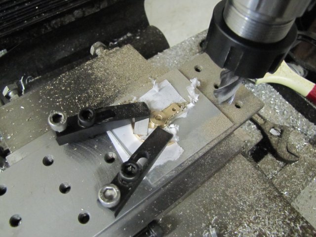
Then I just drilled for the crank pin thread, and milled out the webs with a 14mm end mill. The plans do not specify the size of the arc in the webs, so I guesstimated it at 12mm, but I don't have a 12mm cutter, so I went for 14mm:
normal_IMG_3877.JPG


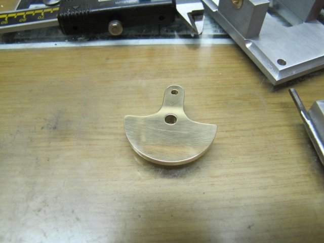
After a bit of cosmetic work with files and emery, and tapping, the web was done:
normal_IMG_3878.JPG


I then attempted to turn the end of a bit of 6mm silver steel for a press fit in the web's central hole for the main shaft, missed the press fit by a tiny bit, and fell back to high-strength retainer to fit the web to the shaft.

At that, I called it a day, and did a quick assembly for the progress shot:


Regards, Arnold
 
Nice work there Arnold, like the R6 decorative additions.

Andrew
 
That's coming along very well. Your build description is so detailed that I won't have to think too much when I do mine ;) Thanks for the good info.

Jan
 
Jim, Andrew & Jan , thanks for checking in :)
It's a pleasure Jan ;)

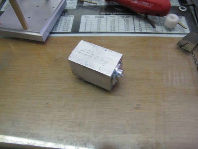
Today it was on to the cylinder. Some 1" aluminium square stock - left over from the Grasshopper engine back when I built it - and showing how much I overtightened my poor chuck on it :-[:
normal_IMG_3880.JPG


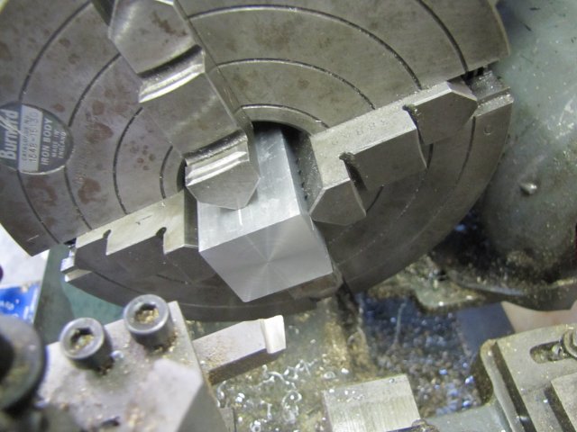
I faced that down to length in the lathe - I just eyeballed it close to center in the four-jaw. It was much quicker than setting up the mill to do it:
normal_IMG_3881.JPG


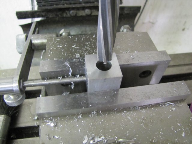
Normally I would have drilled and reamed in the lathe for the cylinder bore as well, but as one of the objectives of building this engine is to get to know my DRO, I moved over to the mill, used the function provided to locate the center of the workpiece, offset it the needed 0.8mm, and then drilled and reamed the bore:
normal_IMG_3883.JPG

You'll also notice I brought the vise backstop up; that would be needed later - just to make life easier.

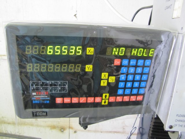
Then I used the PCD function to set up to drill the holes for mounting the cylinder head. When the read-out got to the point where I needed to enter the number of holes to drill, it defaulted to 65535 - one would have expected 0:
normal_IMG_3884.JPG

I actually found this extremely amusing - that value happens to be the maximum number that can be represented using 16 binary bits... It seriously shows up my geeky background :big:. I suspect that that is the maximum number that can be used for "bolt holes" on this unit - though I don't fancy actually drilling that many ::)

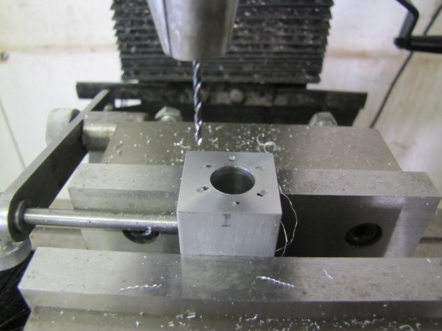
Not being entirely confident in this PCD method and that I got the angles correct, I dotted black marks on the workpiece roughly where I expected the holes should go, as a visual reference, and then followed the cycle with a center drill - spotting each location:
normal_IMG_3885.JPG

;D What do you know... It worked - and is more accurate than myself.

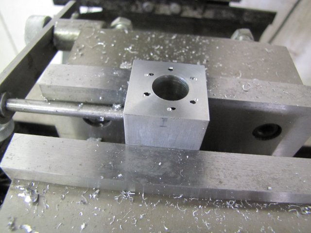
The PCD function fortunately does not exit on its own, so I was able to go back and actually drill each hole (1.6mm to tap M2) in each location:
normal_IMG_3886.JPG

This is where the vise back-stop came into play; to drill the mounting holes on the other end of the cylinder, I just flipped it 180o around relative to the mill's X axis, and still using the same PCD function, drilled the other mounting holes. A nice time-saver.

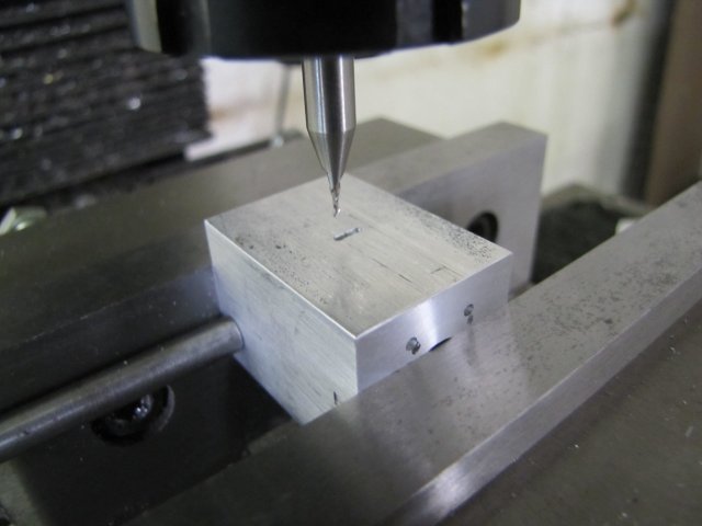
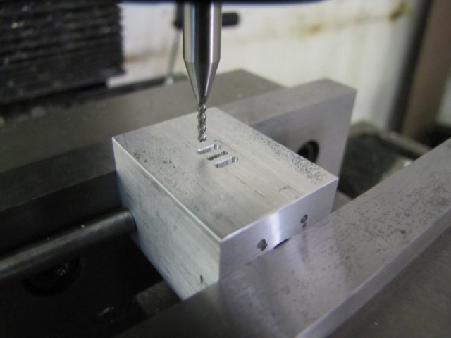
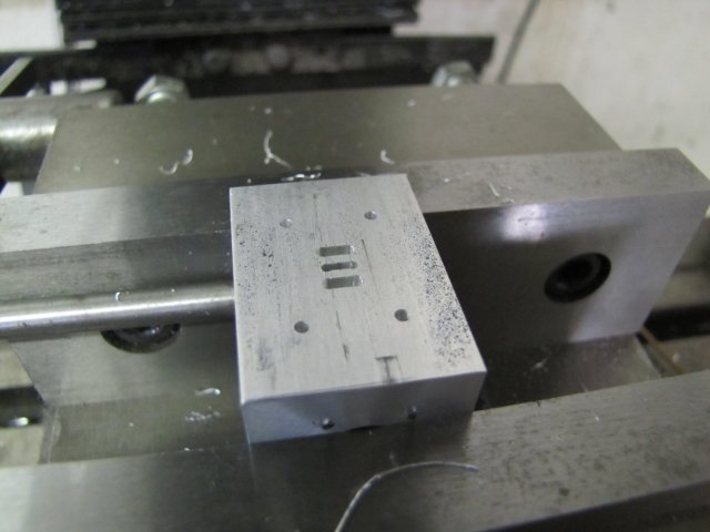
On to the ports. The side hole for the exhaust connection was easy; I drilled it 2.5mm to thread M3. The plans call for three #57 holes from the steam chest side into that. In my metric parlance, that translates roughly, but close enough to, 1.1mm. Last year I treated myself to some 1mm slot mills, so I drilled the holes 1mm, and then used one of the slot mills to actually mill out the port, enlarging the slot to 1.1mm. That officially became the smallest slot I've milled to date :) :
normal_IMG_3887.JPG


The two other ports (1.6mm wide, 3.2mm deep) were easily done with a 1.5mm end mill:
normal_IMG_3888.JPG


I remembered just in time that I needed to poke some more 1.6mm holes in there to mount the steam chest:
normal_IMG_3889.JPG


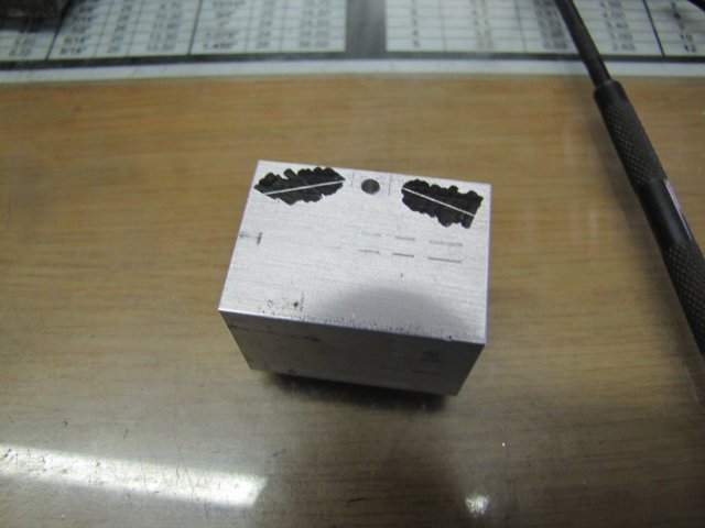
As the cylinder bore is only 12mm compared to the 12.7mm (1/2") on the plans, I had to compensate a bit on the angle of the steam passages. I could just have calculated it out (I do enjoy some maths), but I wasn't in the mood for that, so I just transferred the needed offsets to the sides of the workpiecs, and with a rule drew up the angled lines along which the passages had to be drilled:
normal_IMG_3890.JPG


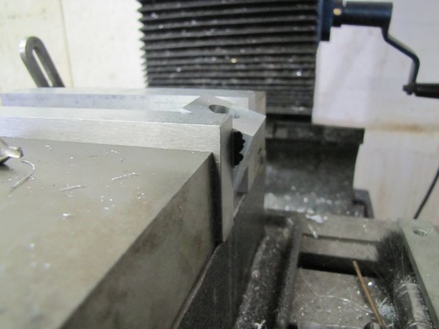
Then I just set the workpiece in the vise with the scribed line aligned with the side of the vise jaw:

Had a bummer of a time getting that photo... It's on the "dark" side of the mill; if you click the image, you can see a more detailed view.

Then started the hole with a center-cutting slot mill - slightly bad practice with it in the drill chuck, but OK for the tiny job here:
normal_IMG_3895.JPG

After that I just drilled the passage 1.6mm - with the workpiece on the end of the vise like that, it's easy to visually see when the drill breaks through into the milled pocket on the side.

Off to the lathe, and with a suitably cobbled-together mandrel, it was easy to turn the round ends of the cylinder - once again just splitting the scribed line on the length:
normal_IMG_3896.JPG


Back to the mill, and bringing the "sides" down to size:
normal_IMG_3897.JPG


Next, the round-robin to get rid of more stock:
normal_IMG_3898.JPG


After quite a bit of fettling with a selection of files and a bit of emery, the cylinder is nearly done. It needs some final cosmetic work and all the holes tapped, but after 7 hours in the shop, I was a bit spent, so I called it a day:


Regards, Arnold
 
I said, and a few other people as well, that once you became accustomed to your DRO, it DOES make life a lot easier.

With almost all of Elmers engines, the cylinder ends are invariably the same style with holes in the same locations, so for those people who are going to be making a few of his engines, and don't have a DRO, it pays to make up a steel drop on drilling jig for all the end holes. It can also be used for drilling the cover plates as well.

mine11.jpg


mine12.jpg


mine13.jpg


It saves having to break out the RT every time, and it only takes minutes to drill all the holes.

Lookin' real good Arnold.


John
 
Nice work Arnold looks really nice. Looking forward to seeing it run.
Brock
 
Thanks for doing such a detailed summary of the cylinder construction. I plan to do a couple of Elmer's engines soon, and was a bit put off by having to make the 1-piece cylinder. Your method makes it seem very straight forward!

Looking good Thm:
 
I've made two of those cylinders in the past. Always fun to see how others tackle the setups. Nice job documenting the build, I know how much extra work that is but it sure does help a lot of people.

Trout
 
Looking really good Arnold.
It is a pleasure watching how you go about your tasks.
Detailed descriptions of builds such as this and the many other excellent builds on this forum are such a valuable resource for us newer machinists. I can't begin to tell you how much I have learnt from following along.

Clive


Thanks John. - That's a different view of Elmer's Mine engine lying on its side :). A great tip on the drilling jig Thm: A slightly thicker one with tap clearance sized holes (or just one hole for that matter) will make a great tapping guide as well; it can be a bit of a chore tapping the holes on the cylinders.

Brock, Thanks :)

Thanks Brian, & it's a pleasure. Don't be put off with the cylinder (or any other "complex" looking parts); it may look daunting on paper, but if you visualize the machining steps in your mind with the tools you have available, it becomes a lot easier. John (Bogstandard) has many times advised that it's a good idea to do this and write down the steps to follow when machining, and I can vouch for this. You might want to have a look at the differences (and similarities) in my #37 Grasshopper build of exactly the same cylinder. I had much less equipment at my disposal when I built that, and the results are pretty much the same.

Trout, thank you :)

Thanks Clive :) The detailed builds was part of what attracted to me to HMEM about three years ago - I'm also a "newer" machinist and continuously learning from what other members post - in fact, that will never end; there is always something to be learnt from how other hobby machinists are going about things. You're doing just fine with your wobbler build, and by showing how you're going about it and the problems you run into, you are already sharing knowledge for others to learn from. Its a pleasure for myself - and I'm sure most other members - to follow along on your build Thm:

I doubt I'll be able to show more build progress before the weekend; some social and official commitments are taking up my evenings - fortunately in a pleasant way :)

Kind regards, Arnold
 
Back
Top