
You are using an out of date browser. It may not display this or other websites correctly.
You should upgrade or use an alternative browser.
You should upgrade or use an alternative browser.
Elmer's #32 - Tall Vertical Open Column
- Thread starter arnoldb
- Start date


Help Support Home Model Engine Machinist Forum:
This site may earn a commission from merchant affiliate
links, including eBay, Amazon, and others.
arnoldb
Well-Known Member
- Joined
- Apr 8, 2009
- Messages
- 1,792
- Reaction score
- 12
Thanks Brian ") - Great tip on the leather Thm:; I've used leather strips with "Brasso" on them to polish up small flywheel spokes. I have some 40mm machine gun casings as well - five of them; I want to make "shot glasses" with them, but the "shots" might be a tad too big ;D
- Great tip on the leather Thm:; I've used leather strips with "Brasso" on them to polish up small flywheel spokes. I have some 40mm machine gun casings as well - five of them; I want to make "shot glasses" with them, but the "shots" might be a tad too big ;D
Stan, thanks - I only remembered my own washer trick after those were parted :hDe: - I didn't want to waste the bits, so I did it the hard way ;D Your memory's better than mine it seems, but it's great to know that some of my methods are useful!
Thanks Jan There's actually still quite a few pieces to make - and all of them fiddly. The steam valve will be easy, and the linkages are fairly straight forward as well, but the little bolts and nuts will take a bit of effort and time...
Kind regards, Arnold
- Great tip on the leather Thm:; I've used leather strips with "Brasso" on them to polish up small flywheel spokes. I have some 40mm machine gun casings as well - five of them; I want to make "shot glasses" with them, but the "shots" might be a tad too big ;DStan, thanks
- I only remembered my own washer trick after those were parted :hDe: - I didn't want to waste the bits, so I did it the hard way ;D Your memory's better than mine it seems, but it's great to know that some of my methods are useful!Thanks Jan
There's actually still quite a few pieces to make - and all of them fiddly. The steam valve will be easy, and the linkages are fairly straight forward as well, but the little bolts and nuts will take a bit of effort and time...Kind regards, Arnold
arnoldb said:Took me a LOT longer to type this up than actually making it
Don't doubt it - KP for going to the trouble to keep us lookenpeepers entertained.
Wonderful documentation as usual.
Regards,
Ken
arnoldb
Well-Known Member
- Joined
- Apr 8, 2009
- Messages
- 1,792
- Reaction score
- 12
Double thanks Ken ; "lookenpeepers" - I like that term ;D
I got a call on Thursday; the brass stock I'd ordered a couple of weeks ago had arrived. Went to fetch it on Friday - two 2m lengths of stock well wrapped in shrink wrap... When I opened it at home yesterday evening, it was two lengths of 3 and 4mm round and not the hex sections I'd ordered :wall: - that'll teach me to check at the supplier. So Monday they'll be getting a visit *knuppel2*. Fortunately I can use the round section - especially the 3mm one.
On to today's bits. First off the fork links for the parallel motion. The rest of the engine seems to be evolving as a mix of aluminium and brass in sort of layers, so I thought these would look OK if made from aluminium rather than the brass specified. As I'll be using small bolts to substitute for the link pins, this can be done; if the original plans are followed some pins need to be soldered to these forks and aluminium wouldn't work.
I squared up a bit of 8mm aluminium plate, and clamped that on the tooling plate on the mill - with suitable packing, bits of paper to prevent slipping, and the vise stop also set to keep the X position for a later machining process. Then I drilled two 1.6mm holes to tap M2 on the left side, and two 2mm holes on the right side - using the DRO to locate them:
Then I shifted the one clamp to allow me to mill out some excess:
The workpiece was flipped, and more excess milled out:
Next, the workpiece was clamped vertically, and a slot milled in the top:
The centering feature for the DRO is really nice to use for jobs like this; take the edge finder, and zero Y on one side when it kicks out, then move to the other side, and when it kicks out, press "Y" and 1/2 and the center is located ;D
Before separating the links from the parent stock, the M2 holes were tapped; its easier to tap things when there's a bit to hold onto and flat surfaces:
A quick bit of work with the slitting saw - one cut at the length of the forks:
Two cuts to separate the forks from the parent stock - I used the height gauge to set the saw height for each cut. The gauge was set to zero at the height of the workpiece, and then adjusted for the required depth, and the spindle adjusted till the top of the slitting saw just touched the gauge foot:
Fresh after slitting off - still in need of the elbow grease toolkit:
After application of the elbow grease toolkit - and finished to match the brushed finish of the rest of the aluminium bits on the engine:
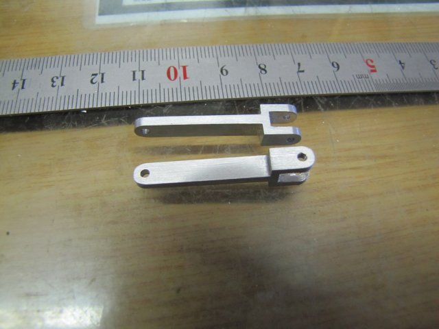
For the links, I milled some brass plate down a bit to get one straight edge on it, and sawed a long enough section off to form one link. Then I heated both bits up and dabbed with some electronics solder to tin them:
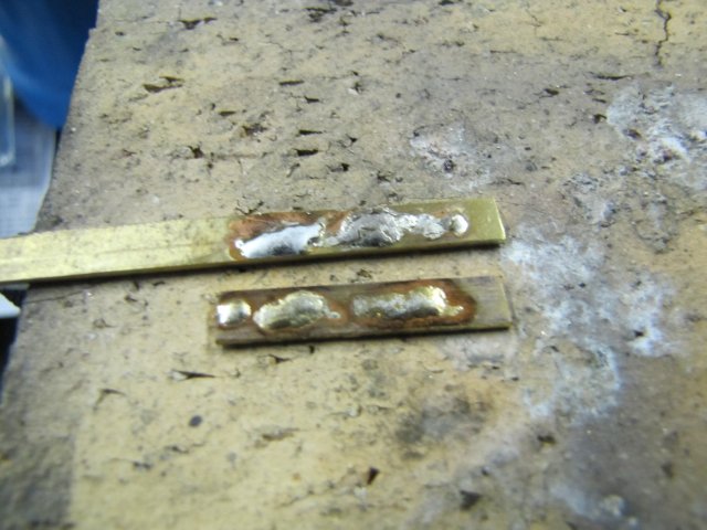
Then I set up the bits with their straight edge on a rusty bit of plate with one of my much abused but well loved toolmaker's clamps also lying on the plate:
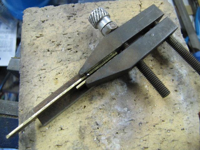
The rusty plate is to prevent excess solder from sticking to it, while helping to keep the bits parallel. The toolmaker's clamp is to force the bits together after heating enough to melt the solder. Heat was applied and the clamp screwed up, and the brass plate bits stuck together.
The soldered assembly was milled to final width:
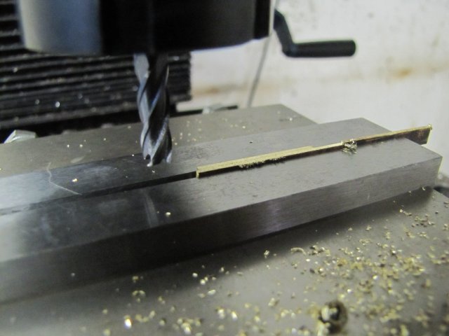
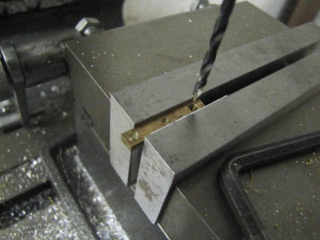
With most of the excess stock sawn off, the workpiece was centered, and holes drilled - 3mm on the outsides and 2mm for the middle one. This is much bigger than on the plans, but the reason will become apparent later in the build:
After more use of the elbow grease toolkit:
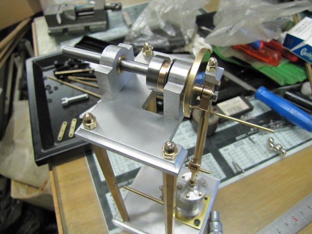
The engine so far - assembled with various odds and ends to keep things in place temporarily:
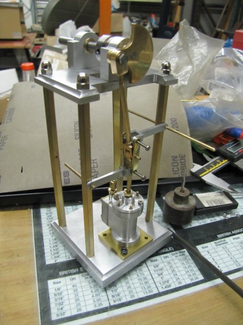
The chromed dome nuts does not look right. I've been trying all suppliers in Windhoek looking for M4 brass dome nuts, and all of them assure me that I won't find any. To quote one supplier: "Your chances are better at getting pregnant than finding brass dome nuts locally". Well, - I think making them is easier (and quicker) than the quoted option ;D
Regards, Arnold
; "lookenpeepers" - I like that term ;DI got a call on Thursday; the brass stock I'd ordered a couple of weeks ago had arrived. Went to fetch it on Friday - two 2m lengths of stock well wrapped in shrink wrap... When I opened it at home yesterday evening, it was two lengths of 3 and 4mm round and not the hex sections I'd ordered :wall: - that'll teach me to check at the supplier. So Monday they'll be getting a visit *knuppel2*. Fortunately I can use the round section - especially the 3mm one.
On to today's bits. First off the fork links for the parallel motion. The rest of the engine seems to be evolving as a mix of aluminium and brass in sort of layers, so I thought these would look OK if made from aluminium rather than the brass specified. As I'll be using small bolts to substitute for the link pins, this can be done; if the original plans are followed some pins need to be soldered to these forks and aluminium wouldn't work.
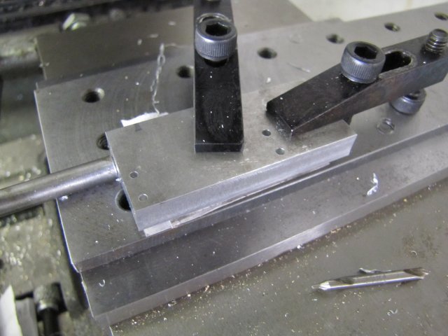
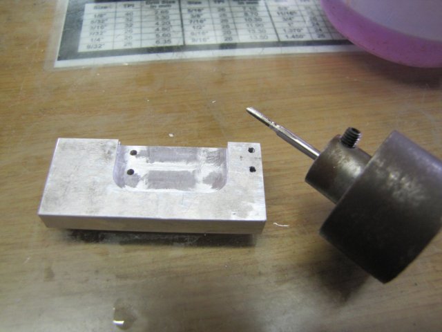
I squared up a bit of 8mm aluminium plate, and clamped that on the tooling plate on the mill - with suitable packing, bits of paper to prevent slipping, and the vise stop also set to keep the X position for a later machining process. Then I drilled two 1.6mm holes to tap M2 on the left side, and two 2mm holes on the right side - using the DRO to locate them:
Then I shifted the one clamp to allow me to mill out some excess:
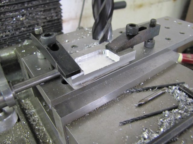
The workpiece was flipped, and more excess milled out:
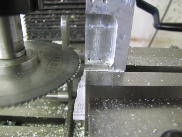
Next, the workpiece was clamped vertically, and a slot milled in the top:
The centering feature for the DRO is really nice to use for jobs like this; take the edge finder, and zero Y on one side when it kicks out, then move to the other side, and when it kicks out, press "Y" and 1/2 and the center is located ;D
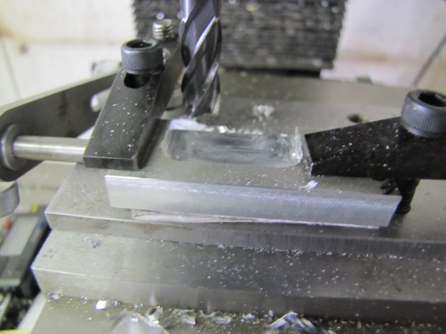
Before separating the links from the parent stock, the M2 holes were tapped; its easier to tap things when there's a bit to hold onto and flat surfaces:
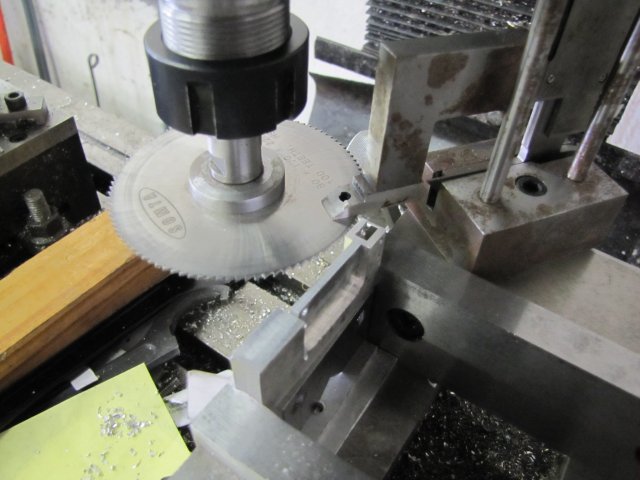
A quick bit of work with the slitting saw - one cut at the length of the forks:
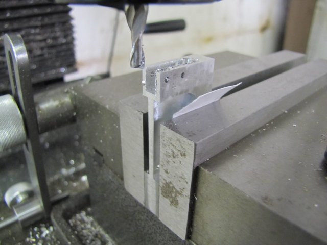
Two cuts to separate the forks from the parent stock - I used the height gauge to set the saw height for each cut. The gauge was set to zero at the height of the workpiece, and then adjusted for the required depth, and the spindle adjusted till the top of the slitting saw just touched the gauge foot:
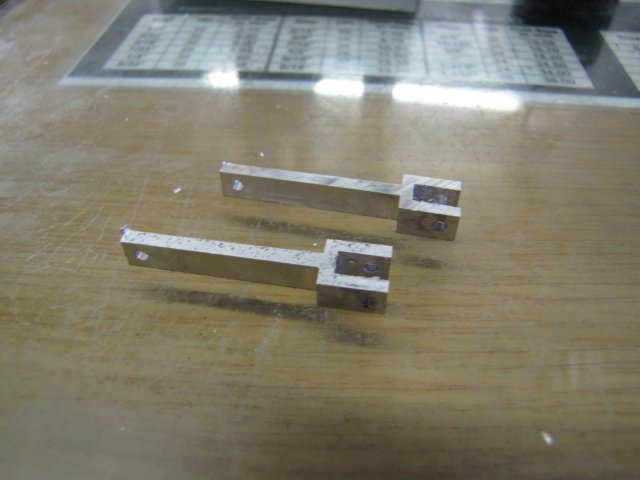
Fresh after slitting off - still in need of the elbow grease toolkit:
After application of the elbow grease toolkit - and finished to match the brushed finish of the rest of the aluminium bits on the engine:
For the links, I milled some brass plate down a bit to get one straight edge on it, and sawed a long enough section off to form one link. Then I heated both bits up and dabbed with some electronics solder to tin them:
Then I set up the bits with their straight edge on a rusty bit of plate with one of my much abused but well loved toolmaker's clamps also lying on the plate:
The rusty plate is to prevent excess solder from sticking to it, while helping to keep the bits parallel. The toolmaker's clamp is to force the bits together after heating enough to melt the solder. Heat was applied and the clamp screwed up, and the brass plate bits stuck together.
The soldered assembly was milled to final width:
With most of the excess stock sawn off, the workpiece was centered, and holes drilled - 3mm on the outsides and 2mm for the middle one. This is much bigger than on the plans, but the reason will become apparent later in the build:
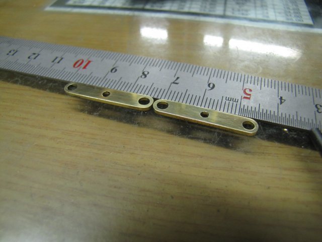
After more use of the elbow grease toolkit:
The engine so far - assembled with various odds and ends to keep things in place temporarily:

The chromed dome nuts does not look right. I've been trying all suppliers in Windhoek looking for M4 brass dome nuts, and all of them assure me that I won't find any. To quote one supplier: "Your chances are better at getting pregnant than finding brass dome nuts locally". Well,
- I think making them is easier (and quicker) than the quoted option ;DRegards, Arnold
Great process for the links, I had no idea how to make those and would have spent forever trying to machine the tiny parts individually. :bow: Also like the idea of using threaded parts instead of pins to join the links, it should look a lot better.
Jan
Jan
arnoldb
Well-Known Member
- Joined
- Apr 8, 2009
- Messages
- 1,792
- Reaction score
- 12
Thanks Dave - making that tooling plate has proven to be some of the best time I've spent on tool building. It does need a couple of accessories though - eccentric clamps for holding down thin workpieces and so on. And fences - when I built it Marv suggested those, and for work like this it would be really handy.
Dankie Andrew - of course; the kit has to justify the expense... a bit anyway :big:
Vince, thanks I don't have to imagine it; been there done that :big:. The tooling plate Dave mentioned was made by reading the hand wheels - to drill, slightly countersink and to power tap each hole with the three successive M6 taps. The DRO would have made that lot MUCH easier ;D
Thanks Jan - any method to make them will work, but I'm inherently lazy, so I try and find easy ways to do things. The often-used term about making as much as possible of small parts while they are still attached to the parent stock also helps I hope the threaded parts will work out OK; it's a lot of additional and very time-consuming work for such small details.
Well, not much done today, but some progress is better than none...
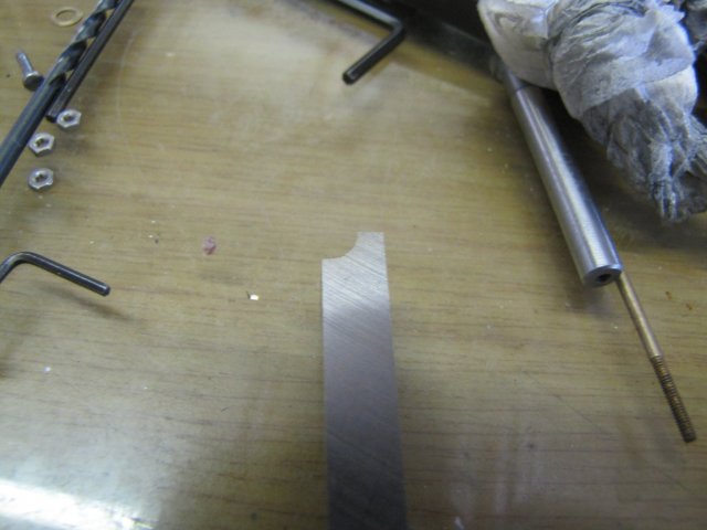
With a brand new 6mm HSS blank in hand I spent a couple of minutes on the bench grinder grinding an approximate 3mm radius on the tip, and a couple of minutes more with the Dremel and a round stone to hone it a bit:
A quick try-out on some hex brass, and a satisfactory dome evolved:
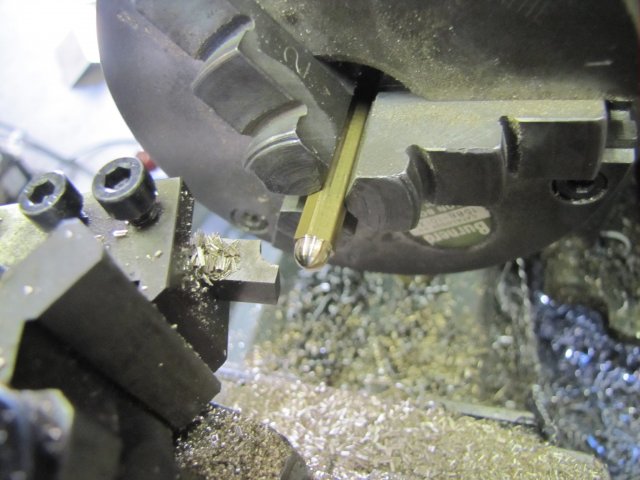
Making similarly sized dome nuts this way wouldn't be too easy, so I started making them the other way around - drill and tap the hex brass, touch the end at a shallow angle with a file to add some clearance on the corners so that they wouldn't scratch the engine table while tightening down, and part off. The parting tool was a tiny tad below the lathe's centerline, but that was OK, as it was easy to just break off each bit after parting; it also saved me from digging through the swarf pile each time to find the bits ;D:
I made a couple of extras, just in case. It was easy and quick enough:
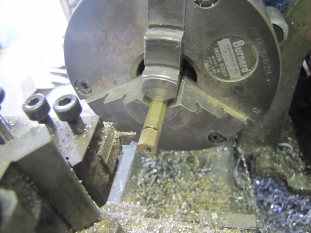
Then I chucked up a 4mm cap screw from behind in the small collet chuck - with just enough thread sticking out for maximum engagement in the workpieces, and then each workpiece was threaded on to seat against the collet and turned down. Very carefully... This was essentially a "forming" operation, and that adds a lot of strain while turning. While turning the first nut, I locked the carriage at the point the workpiece looked good to go, and I took a note of the cross-slide reading. This meant I could turn all the nuts the same:
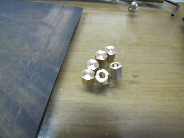
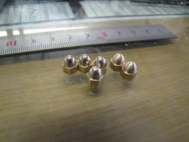
After some spit 'n polish, I had four acceptable-looking nuts - the other two I left as-is for now
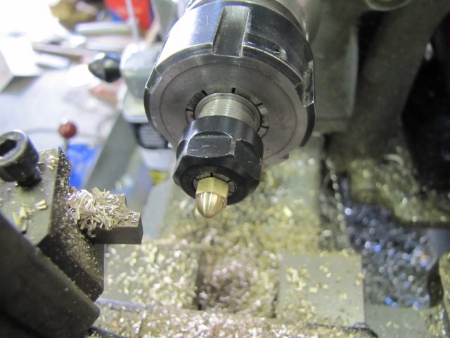
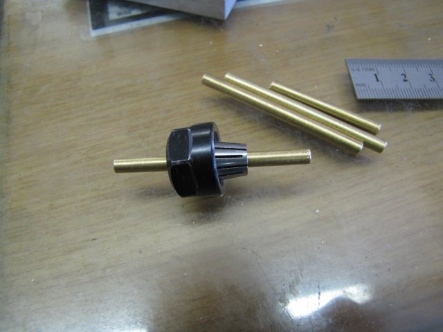
I have a length of 3mm OD x 2mm ID brass pipe - from this I parted off some 1.4mm long sections. The one was a bit more than 1.4mm - but I can shorten it if needed - such as in the case where one of the others goes into the fourth dimension:
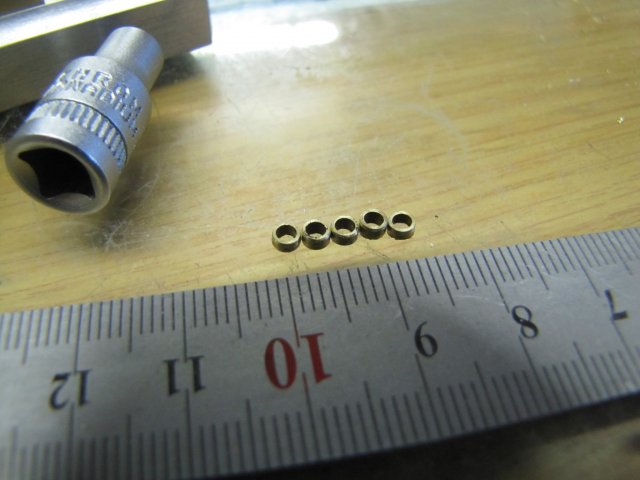
The little pipe sections will be used as the bushes for the links - meaning I don't have to fiddle about making run-out grooves for the threads in the M2 bolts when I make those:
That was all I did for today... But at least there was some bits made, and I'm fairly happy with how the dome nuts look on the table:
Winter's started to hit home here in Windhoek - I know this because yesterday evening Shrek decided to climb in my jacket rather than perch on my shoulder as usual:

: It's difficult to take a photo if you can't see the screen to get focus...
Regards, Arnold
- making that tooling plate has proven to be some of the best time I've spent on tool building. It does need a couple of accessories though - eccentric clamps for holding down thin workpieces and so on. And fences - when I built it Marv suggested those, and for work like this it would be really handy.Dankie Andrew
- of course; the kit has to justify the expense... a bit anyway :big:Vince, thanks
I don't have to imagine it; been there done that :big:. The tooling plate Dave mentioned was made by reading the hand wheels - to drill, slightly countersink and to power tap each hole with the three successive M6 taps. The DRO would have made that lot MUCH easier ;DThanks Jan
- any method to make them will work, but I'm inherently lazy, so I try and find easy ways to do things. The often-used term about making as much as possible of small parts while they are still attached to the parent stock also helps I hope the threaded parts will work out OK; it's a lot of additional and very time-consuming work for such small details.Well, not much done today, but some progress is better than none...
With a brand new 6mm HSS blank in hand I spent a couple of minutes on the bench grinder grinding an approximate 3mm radius on the tip, and a couple of minutes more with the Dremel and a round stone to hone it a bit:
A quick try-out on some hex brass, and a satisfactory dome evolved:
Making similarly sized dome nuts this way wouldn't be too easy, so I started making them the other way around - drill and tap the hex brass, touch the end at a shallow angle with a file to add some clearance on the corners so that they wouldn't scratch the engine table while tightening down, and part off. The parting tool was a tiny tad below the lathe's centerline, but that was OK, as it was easy to just break off each bit after parting; it also saved me from digging through the swarf pile each time to find the bits ;D:
I made a couple of extras, just in case. It was easy and quick enough:
Then I chucked up a 4mm cap screw from behind in the small collet chuck - with just enough thread sticking out for maximum engagement in the workpieces, and then each workpiece was threaded on to seat against the collet and turned down. Very carefully... This was essentially a "forming" operation, and that adds a lot of strain while turning. While turning the first nut, I locked the carriage at the point the workpiece looked good to go, and I took a note of the cross-slide reading. This meant I could turn all the nuts the same:
After some spit 'n polish, I had four acceptable-looking nuts - the other two I left as-is for now

I have a length of 3mm OD x 2mm ID brass pipe - from this I parted off some 1.4mm long sections. The one was a bit more than 1.4mm - but I can shorten it if needed - such as in the case where one of the others goes into the fourth dimension:
The little pipe sections will be used as the bushes for the links - meaning I don't have to fiddle about making run-out grooves for the threads in the M2 bolts when I make those:
That was all I did for today... But at least there was some bits made, and I'm fairly happy with how the dome nuts look on the table:
Winter's started to hit home here in Windhoek - I know this because yesterday evening Shrek decided to climb in my jacket rather than perch on my shoulder as usual:
:
It's difficult to take a photo if you can't see the screen to get focus...Regards, Arnold
arnoldb
Well-Known Member
- Joined
- Apr 8, 2009
- Messages
- 1,792
- Reaction score
- 12
Thanks Dave - scratch.gif Now, why didn't I think of that :big: Something to keep in mind for future fixture plates; it'll be nice to spread the work!When I make them, I leave the blank holes and tap them as I need them
Brian, thanks
, they were easy to make. The biggest concern I had was forming the dome with the bits just engaged by the threads. The simple rule is to have a very sharp toolbit and to take it easy on the in-feed.Hopefully I can give the build a bit of a go this coming weekend; too cold in the evenings for shop now.
Kind regards, Arnold
Arnold,
I have been watching your build with great interest. I am building Elmers #29. Since I am new at this I find your pictures and text to be of great value for me. I am currently starting on the cylinder and following your procedure step for step. I hope to reach your level of expertise some day.
Ed (RCGUY)
arnoldb
Well-Known Member
- Joined
- Apr 8, 2009
- Messages
- 1,792
- Reaction score
- 12
Thanks Ron - The posts will pretty much be weekend-to weekend now; a sudden cold spell has hit, and I tend to stay out of the shop if the machines turn a cold shoulder
Ed, thank you - I'm glad there's something of value to you in the posts. I very nearly built the #29 as this build, as it's also a really nice-looking engine, but I wanted a "quick" build and I have some other ideas in store for the #29 which will make my build of it very slow. You're doing a great job on it :bow: - keep it up! I've been following along, just have not posted yet. As to "expertise" - you already have it; it comes from the heart.
Today I made a couple of bits, then digressed from the build for a bit of tooling.
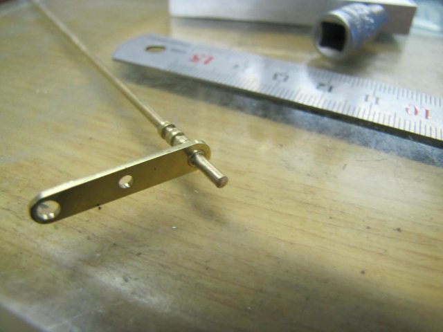
First up, the piston-rod to connecting rod link bolt - some 4mm brass round turned down to 2mm for a length and then I just filed hex flats at the thick end, using the big collet chuck's slots as indexing grooves. Four strokes with the fine 200mm flat file in each position; after the first rotation the flats weren't quite right, so a further 3 strokes for each face:
After threading a 2mm long section at the end with the tailstock die holder, parting off and a bit of clean-up, the bolt was done:
Four short bolts followed - for the link-to-fork arm connections:
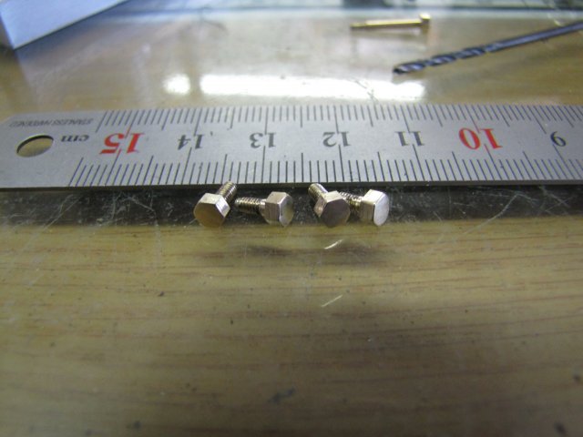
The last bit for the engine I made today was the bolt for the valve rod:
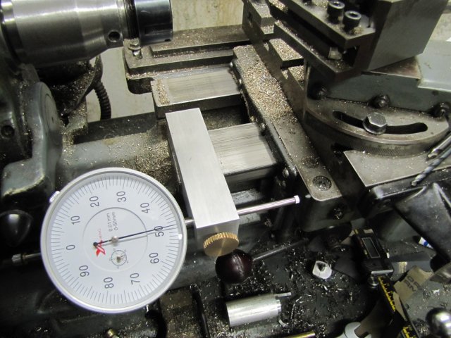
I need to make at least 13 2mm nuts and a lot of thin 2mm washers... So far I'd been eyeballing the bolt head sizes, but it takes longer and screw-ups are very easy to make with the thicknesses, so I digressed to build an accessory to help me with the rest of the small bits tomorrow:
Regards, Arnold
- The posts will pretty much be weekend-to weekend now; a sudden cold spell has hit, and I tend to stay out of the shop if the machines turn a cold shoulder Ed, thank you
- I'm glad there's something of value to you in the posts. I very nearly built the #29 as this build, as it's also a really nice-looking engine, but I wanted a "quick" build and I have some other ideas in store for the #29 which will make my build of it very slow. You're doing a great job on it :bow: - keep it up! I've been following along, just have not posted yet. As to "expertise" - you already have it; it comes from the heart.Today I made a couple of bits, then digressed from the build for a bit of tooling.
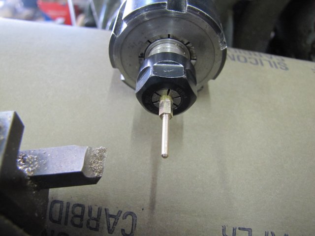
First up, the piston-rod to connecting rod link bolt - some 4mm brass round turned down to 2mm for a length and then I just filed hex flats at the thick end, using the big collet chuck's slots as indexing grooves. Four strokes with the fine 200mm flat file in each position; after the first rotation the flats weren't quite right, so a further 3 strokes for each face:

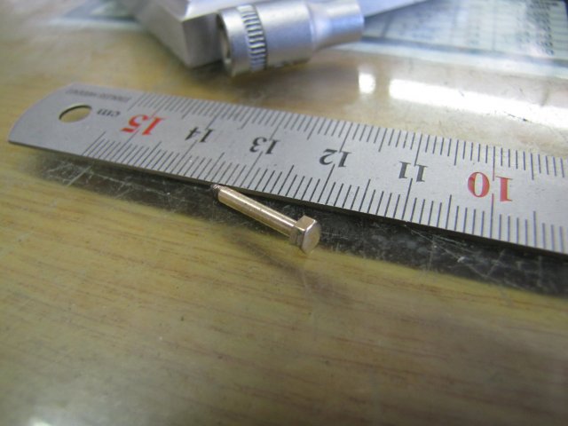
After threading a 2mm long section at the end with the tailstock die holder, parting off and a bit of clean-up, the bolt was done:
Four short bolts followed - for the link-to-fork arm connections:

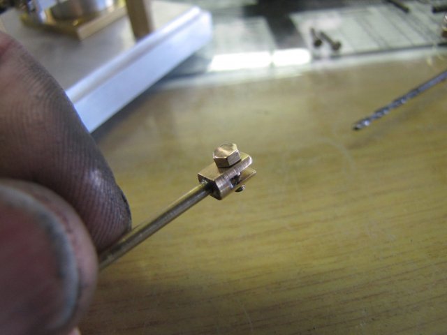
The last bit for the engine I made today was the bolt for the valve rod:

I need to make at least 13 2mm nuts and a lot of thin 2mm washers... So far I'd been eyeballing the bolt head sizes, but it takes longer and screw-ups are very easy to make with the thicknesses, so I digressed to build an accessory to help me with the rest of the small bits tomorrow:
Regards, Arnold
arnoldb
Well-Known Member
- Joined
- Apr 8, 2009
- Messages
- 1,792
- Reaction score
- 12
:-X I didn't get a chance to update yesterday evening, but it's a bit boring anyway...
I just made about twenty 2mm washers x 0.2mm thick from some 4mm brass rod. Stan (sshire) mentioned earlier when I made some other thin washers about a method I'd shown in another thread, but I'll just show it here again.
The bit of stock just grooved up with the parting tool to leave "flanges" the thickness of the wanted washers, and with the grooving done to leave a core just smaller than the hole in the washers needs to be:
It's a bit of a toss-up; you can't have too much stock sticking out from the chuck, as the groove parting will go pear-shaped. But one wants the maximum number of washers possible for one go.
Then drill through the lot - using a light feed rate with as stiff / short a drill as you can get. If you drill too hard, either the workpiece or the drill will deflect resulting in tears (at best washers with off-center holes, and at worst, a ruined bit of valuable stock and/or a broken drill bit). I just used a 2mm center drill here as I wanted the holes 2mm and the 2mm center drill is about as stiff as you can get:
That leaves a bunch of washers sitting neatly on the drill.
Here's the batch from the previous photo:

They don't look good - well, to be honest, they look pretty crappy - and ended up being slightly dish-shaped. The deformation was due to my parting tool both flexing and being slightly blunt, hence pushing over the thin flange while doing the parting cuts. Not a major problem though; in some locations I can use the "dishing" to benefit, and where that's not OK, I'll just squeeze the washers flat in my old milling vise.
: Taking a macro photo also tends to exaggerate flaws - all the tiny imperfections looks HUGE when enlarged... - that's my theory anyway :big:
I really need to look into getting a selection of shim stock and a press for this kind of job on the common sizes I'm doing; turning up a punches and dies from silver steel (drill rod) and hardening those up to punch washers from the appropriate shim stock would be a lot easier and neater...
Next I cut some lengths of 4mm brass rod to extend out both ways from the ER11 collet chuck for about 18mm - which is a carefully chosen random distance at which I'd be comfortable to do light milling and parting on:
The one section's a bit shorter, as that was the left-over bit from the section of rod I cut up.
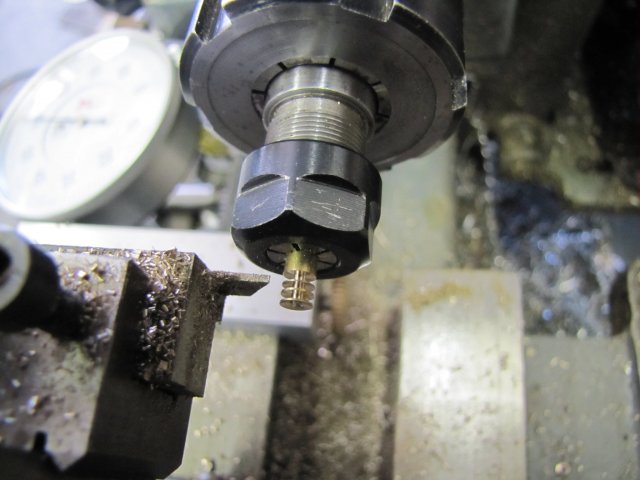
On to the Mill, and with the dividing head mounted, I started milling the brass rod down to hexagon shape. VERY carefully, and with a sharp cutter:
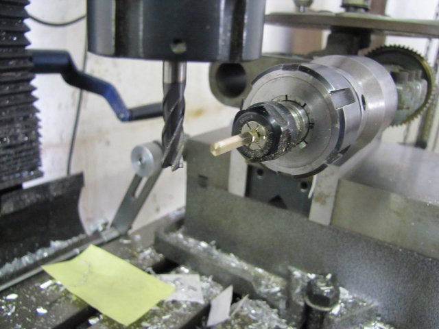
There's a lot of excess sticking out, and going about things hastily would end up in tears. Closer to the collet chuck, the feed rate can be increased as the workpiece gets stiffer toward it.
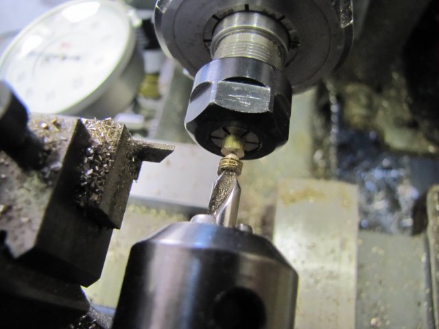
Once I'd milled hex sections on the bits of brass round, back to the lathe, drilled through 1.6mm to tap M2 and parted off 1.7mm thick sections, catching them on a bit of wire held in the tailstock chuck:
I forgot to take a photo of what the milled sections looked like - so I snapped this after I'd parted off some nut blanks:
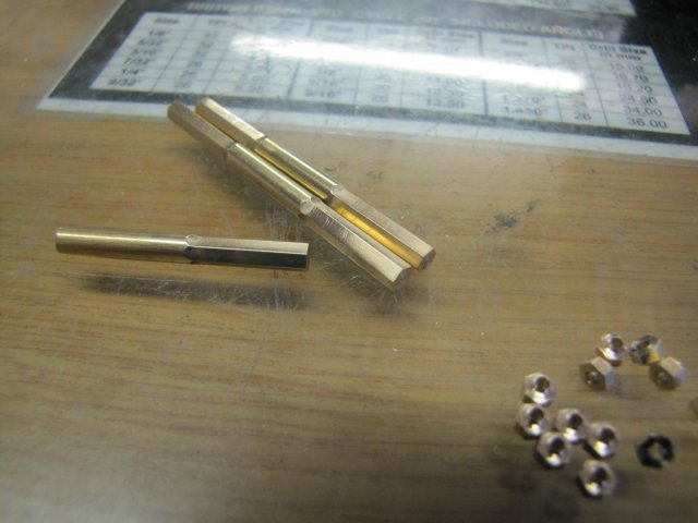
A bit more parting off later, and I had a selection of nut blanks. On the left, the blanks are 2mm thick, on the right 1.7mm, and in the middle is a commercial M2 stainless steel nut, that measures out at 1.4mm thick:
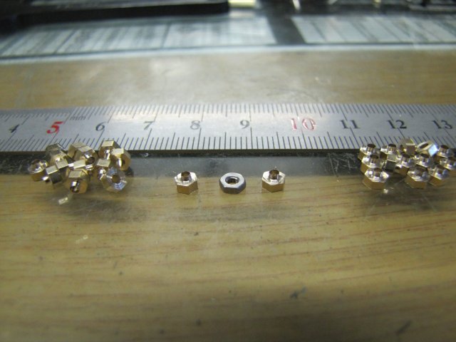
All in their gory detail so far; the nuts still need to be cleaned up and tapped M2, but I've hatched a plan for that to save some energy that entails a bit of shopping this week when I get a chance. I just hope my plan will work :noidea: - otherwise I'm going to sit with a lot of egg on my face :fan:
:hDe: Shucks, this build have come a long way from just starting a relatively simple engine build to test a set of DROs to messing around with nuts & bolts... I guess that's just part of the fun ;D
Regards, Arnold
I just made about twenty 2mm washers x 0.2mm thick from some 4mm brass rod. Stan (sshire) mentioned earlier when I made some other thin washers about a method I'd shown in another thread, but I'll just show it here again.
The bit of stock just grooved up with the parting tool to leave "flanges" the thickness of the wanted washers, and with the grooving done to leave a core just smaller than the hole in the washers needs to be:
It's a bit of a toss-up; you can't have too much stock sticking out from the chuck, as the groove parting will go pear-shaped. But one wants the maximum number of washers possible for one go.
Then drill through the lot - using a light feed rate with as stiff / short a drill as you can get. If you drill too hard, either the workpiece or the drill will deflect resulting in tears (at best washers with off-center holes, and at worst, a ruined bit of valuable stock and/or a broken drill bit). I just used a 2mm center drill here as I wanted the holes 2mm and the 2mm center drill is about as stiff as you can get:
That leaves a bunch of washers sitting neatly on the drill.
Here's the batch from the previous photo:

They don't look good - well, to be honest, they look pretty crappy - and ended up being slightly dish-shaped. The deformation was due to my parting tool both flexing and being slightly blunt, hence pushing over the thin flange while doing the parting cuts. Not a major problem though; in some locations I can use the "dishing" to benefit, and where that's not OK, I'll just squeeze the washers flat in my old milling vise.
:
Taking a macro photo also tends to exaggerate flaws - all the tiny imperfections looks HUGE when enlarged... - that's my theory anyway :big:I really need to look into getting a selection of shim stock and a press for this kind of job on the common sizes I'm doing; turning up a punches and dies from silver steel (drill rod) and hardening those up to punch washers from the appropriate shim stock would be a lot easier and neater...
Next I cut some lengths of 4mm brass rod to extend out both ways from the ER11 collet chuck for about 18mm - which is a carefully chosen random distance at which I'd be comfortable to do light milling and parting on:
The one section's a bit shorter, as that was the left-over bit from the section of rod I cut up.
On to the Mill, and with the dividing head mounted, I started milling the brass rod down to hexagon shape. VERY carefully, and with a sharp cutter:
There's a lot of excess sticking out, and going about things hastily would end up in tears. Closer to the collet chuck, the feed rate can be increased as the workpiece gets stiffer toward it.
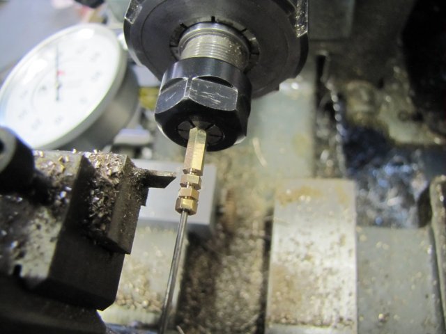
Once I'd milled hex sections on the bits of brass round, back to the lathe, drilled through 1.6mm to tap M2 and parted off 1.7mm thick sections, catching them on a bit of wire held in the tailstock chuck:
I forgot to take a photo of what the milled sections looked like - so I snapped this after I'd parted off some nut blanks:
A bit more parting off later, and I had a selection of nut blanks. On the left, the blanks are 2mm thick, on the right 1.7mm, and in the middle is a commercial M2 stainless steel nut, that measures out at 1.4mm thick:

All in their gory detail so far; the nuts still need to be cleaned up and tapped M2, but I've hatched a plan for that to save some energy that entails a bit of shopping this week when I get a chance. I just hope my plan will work :noidea: - otherwise I'm going to sit with a lot of egg on my face :fan:
:hDe: Shucks, this build have come a long way from just starting a relatively simple engine build to test a set of DROs to messing around with nuts & bolts... I guess that's just part of the fun ;D
Regards, Arnold
Forgive the newbie question, but this is how I must learn - Could you have threaded a length of the hex rod, prior to parting off the nuts, and then just run each nut over the tap again to clean up the mess from parting (if any) ?
- Ryan
- Ryan
arnoldb
Well-Known Member
- Joined
- Apr 8, 2009
- Messages
- 1,792
- Reaction score
- 12
Thanks Jan - Yes, I agree there's a certain level of pleasure in making the really small bits... Sometimes it borders on masochism ;D
Hi Ryan, no problem; please ask away if you have questions
Yes, I could have threaded before parting and run each nut over the tap afterwards - in fact, that's how I've done it in the past.
My M2 taps can only thread to a depth of 8mm though, so that means making 2 nuts at a time if the loss of material for the parting tool is taken into account. That becomes very time-consuming with all the tool changes in between, and it also gets easy to cross-thread the nuts while picking up the left-over threads in the parent stock for each 2-nut batch. So I'm trying a different method to see if I can make things a bit easier and quicker...
Kind regards, Arnold
- Yes, I agree there's a certain level of pleasure in making the really small bits... Sometimes it borders on masochism ;DHi Ryan, no problem; please ask away if you have questions
Yes, I could have threaded before parting and run each nut over the tap afterwards - in fact, that's how I've done it in the past.
My M2 taps can only thread to a depth of 8mm though, so that means making 2 nuts at a time if the loss of material for the parting tool is taken into account. That becomes very time-consuming with all the tool changes in between, and it also gets easy to cross-thread the nuts while picking up the left-over threads in the parent stock for each 2-nut batch. So I'm trying a different method to see if I can make things a bit easier and quicker...
Kind regards, Arnold
Similar threads
- Replies
- 1
- Views
- 589