
You are using an out of date browser. It may not display this or other websites correctly.
You should upgrade or use an alternative browser.
You should upgrade or use an alternative browser.
Elmer's #32 - Tall Vertical Open Column
- Thread starter arnoldb
- Start date


Help Support Home Model Engine Machinist Forum:
This site may earn a commission from merchant affiliate
links, including eBay, Amazon, and others.
arnoldb
Well-Known Member
- Joined
- Apr 8, 2009
- Messages
- 1,792
- Reaction score
- 12
Rof} Jim, side-effects of my career move last monthWell how *dare* they(sniff)? :big:
") I'm really enjoying my new job though, so I don't begrudge the infringement ;D
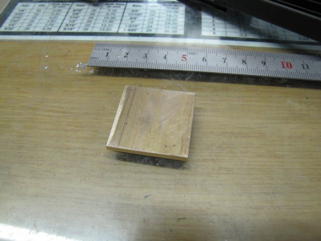
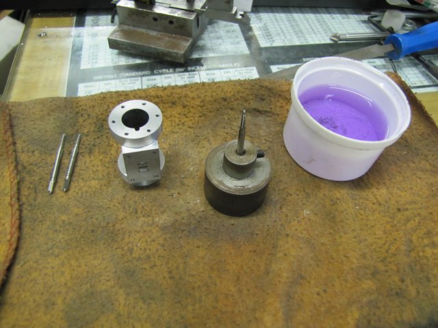
I'm really enjoying my new job though, so I don't begrudge the infringement ;DThis afternoon I started off with a bit of 6mm aluminium plate, and two bits of sorry-looking 1.2mm brass plate for the steam chest, valve plate and steam chest cover:

The bit of aluminium was milled to size, and then I located what would be the center of the steam chest, and from there coordinate drilled the mounting holes, as well as four 3mm holes in what would be the corners of the cut-out:

Then I started milling out the cavity with a 4mm end mill, but 0.2mm under-size on all sides:

A final clean-up pass to take off the 0.2mm excess left nice and smooth edges:

For the next step, I reverted to some manual lay-out for a change:

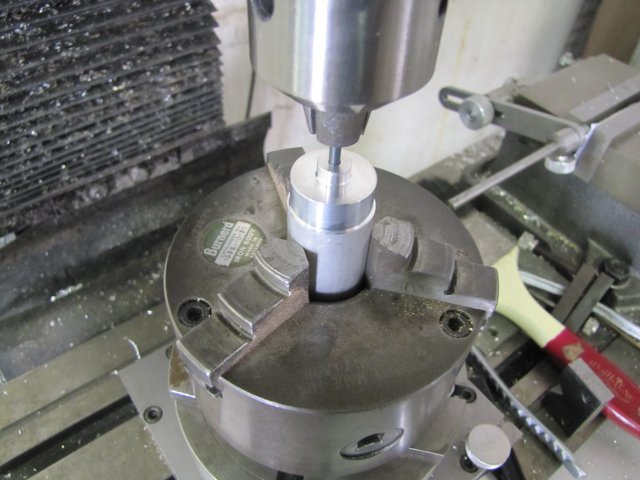
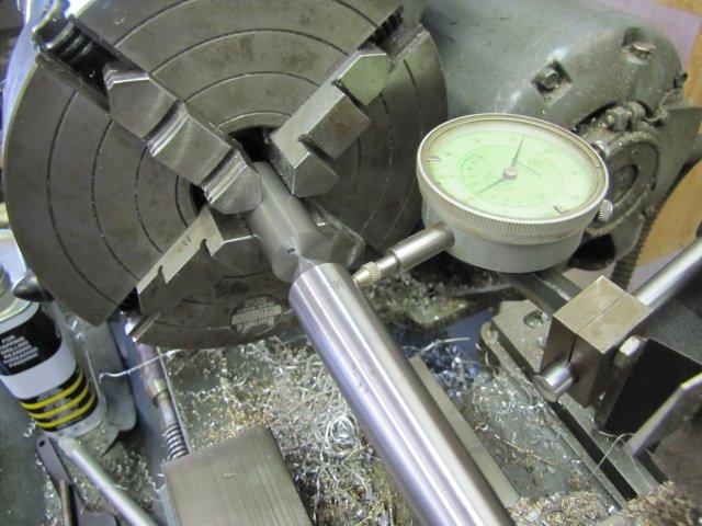
Off to the lathe and clocked up in the 4-Jaw; When I started out in the hobby, this was one of the most time-consuming things to do, but has gotten much easier; today it took me literally less than a minute to adjust to less than 0.02mm run-out; it nearly takes longer to set up the dial indicator...:

The boss turned - with the block marked out as it was, it's easy to turn to the marked-out line as it remains visible while the workpiece is revolving:

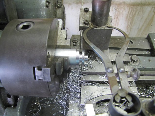
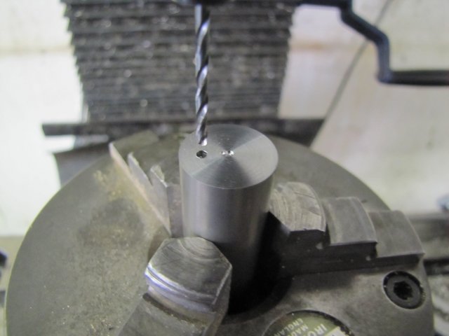
Then I center drilled and drilled the boss through with a 2mm drill, as I will use a 2mm valve rod. The other end of the stem chest needs a 1.6mm (1/16") hole according to the plans, but as I'm using metric threads, I had to compensate a bit. From the plans, the valve rod has a 1/16" end and #2-56 threads for the valve nut. For my metric threading equipment, the thread will be M2, but I know my M2 die cuts to a core depth of less than 1.6mm, but more than 1.5mm, so the hole must be 1.5mm and the end of the valve rod as well.
If one would try and start the opposite hole with a 1.5mm drill, it is more than likely to wander, so I also spotted the far side of the steam chest with the 2mm drill, as it is a bit stiffer and less likely to wander. The spotting mark is just to the depth of the drill point:

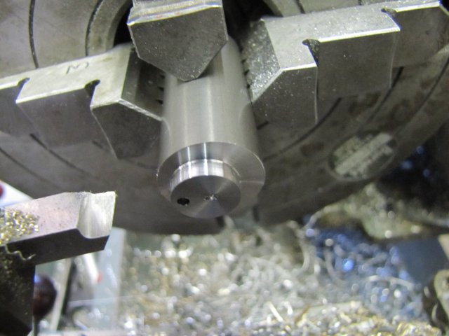
Drilling the back hole to depth can be a bit tricky. As I'm lazy by nature, I just inserted the 1.5mm drill to touch the spotted hole earlier, and marked it with a permanent marker for the depth it must go to. The left side of the black dot (well... top in the photo, but left when you're standing in front of the lathe) is at the required depth, and as you can see, there's not a whole lot of drill shank left to chuck up on:

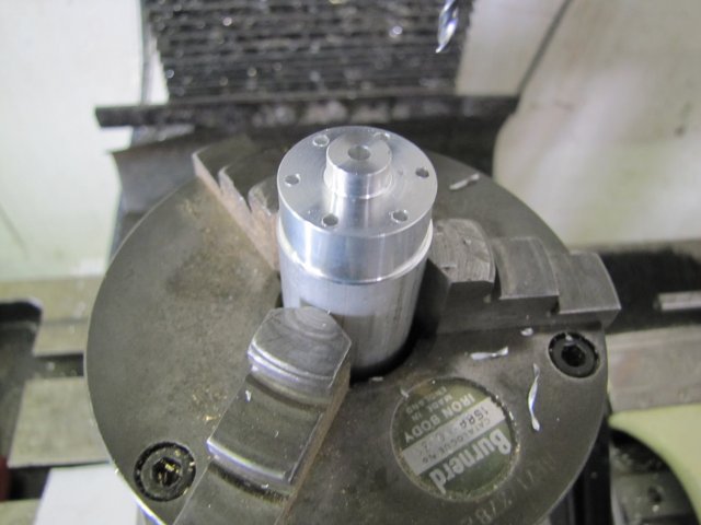
After I drilled the 1.5mm hole, I flipped the workpiece in the chuck to turn the boss on the other side. The boss is purely cosmetic, and does not need to be turned to a high degree of accuracy, so I cheated a bit. By just loosening two adjacent jaws on the 4-jaw chuck (#1 and #2), flipping the workpiece, and tightening it up again using the same two jaws that were loosened, it gets back close enough to center so that no-one will notice. Well, everyone who read this will know, but that's OK with me
Then I turned the boss; and just free-hand turned the approximate curve on the end:
The curve was completed with a small file - very very carefully, as I was working fairly close to the chuck jaws with file and fingers. If you're not comfortable doing this, you could just grind up a suitable form tool to turn the curve.
After a quick rub-down on emery to smooth the surfaces, the steam chest was done:

:
Not quite done... I forgot to drill and tap it for the steam connector.On to the bits of brass plate, and I just milled them down to size and drilled the mounting holes as a pair. The vise backstop in combination with the DRO is really a pleasure to use, as I just used the stop to maintain workpiece X position to remove the plate that will become the cover, and then I spot-drilled with a 1mm center drill for the steam ports on the valve plate:

The holes on the plan is for a #57 drill. In Metric parlance, that is 1.092mm. On the #37 Grasshopper I drilled the holes 1mm, and it runs like a champ, but I decided to go for 1.1mm holes on this one; closer to the actual #57 size. With the hole locations spotted, it was easy to just run through the coordinates and poke the holes through with the mill running at it's maximum 1200RPM spindle speed:

On to some flat-lapping of the valve plate with a bit of 320 emery paper on the glass sheet that serves as my surface plate:

Once it was flat and free of blemishes on both sides, I followed the flat-lapping up with some 600 grit paper to smooth it out a bit more.
The steam chest cover was also tidied up a bit, and the two pieces were done for now:

Well, what do you know... Even though all the bits were made separately for the most part, all the mounting holes line up
:
At that point, I decided that the Eccentric Nut needed a bit of attention... So I closed up shop and indulged in the first bottle of Namibia Breweries' Urbock beer that I found for the season. There's an upside and a downside to this exclusive seasonal beer... The upside is that I particularly like it, and the downside is that it's availability really rings in the Winter season here in Namibia. Winter's a small price to pay for a good beer by an eccentric nut ;D
Regards, Arnold
It's all going well Arnold. Along the way you have answered a few questions I had about machining processes for this engine and I will be using your build as a reference for mine :bow:
Winter beers where a feature of life in England and I miss them but would rather have an Australian winter than an English one
Winter beers where a feature of life in England and I miss them but would rather have an Australian winter than an English one
arnoldb
Well-Known Member
- Joined
- Apr 8, 2009
- Messages
- 1,792
- Reaction score
- 12
Thanks Jan I'm glad that you're finding this useful. If you do have any questions please fire away; it helps other people too. I'm just blundering along in my own style, so it's not necessarily right or the best way. Everybody's welcome to chip in with ideas and suggestions.
:big: I might complain about Namibian winters, but they are much more like the Aussie ones. And no thick layers of white stuff on the ground either; I've only ever touched snow once in my life, and seen it in real life from a distance about 5 times. The only downside is the humidity here; today it was nice and humid, and right now as I'm posting, it's a whopping big 33%. Later in the week that will most likely drop to about 20% - and then people wonder why Namibians drink a lot ;D
Not much done today, but some progress none-the-less.
A bit of 25mm round aluminium bar turned for the face of the inboard cylinder head, and drilled through at 3.2mm:

The 3.2mm is for the 1/8" brazing rod that I'm going to use as the piston rod. That's quite a bit thicker than the 3/32" the plans call for. I have 2mm and 3.2mm rod available, and while I could knock up a box tool to turn the 1/8" rod down to 2.4mm (~3/32"), the engine might actually look better with the thicker rod, even though it would impair performance slightly on the down-stroke by the loss of upper cylinder volume.
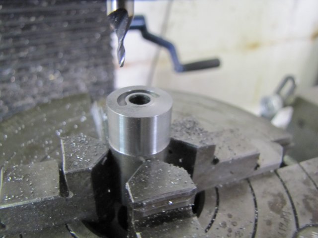
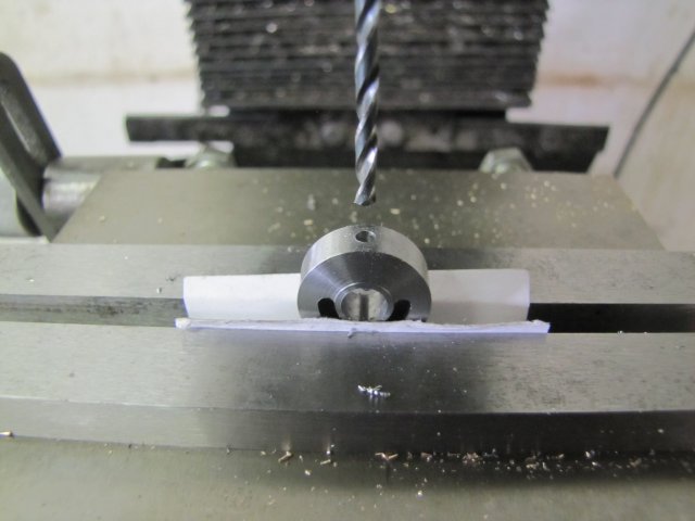
Even though this thread is as much about getting to grips with the DRO as it is about building an engine, for the next step I reverted back to what I know well and do fairly quickly. So, chuck unmounted from the lathe - workpiece-and-all - and re-mounted on the rotary table on the mill. I just used the 3.2mm drill chucked up in reverse in the mill chuck to center the RT to the spindle, and zeroed the DRO on that:
Then I just dialed in the 9.525mm PCD offset on the Y axis (3/4" ~19.05mm - halve of that = 9.525mm) and used the RT to index the holes for drilling:
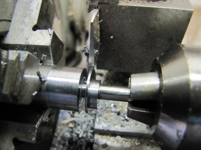
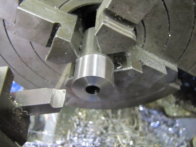
Back to the lathe, and then drilled 4.2mm part-way and tapped M5 for the packing nut, and then I started parting away. The cylinder head needs a small boss on the back side, and I just used a pair of calipers to check for size:
Inboard head done:

Next up, the outboard head. I don't know if I'm starting to turn into a grumpy old man and getting pedantic, or just plain having fun in my own perverse personal way, but thinking through the looks of the engine and what I'd like as an end result, I thought it would be nice to make the outboard head in brass to contrast a bit with the aluminium cylinder and base. So I squared up a bit of 1/8" (3.2mm) brass plate:
Then I clamped it up on the mill and poked a lot of holes in it. I coordinate drilled the 3mm mounting holes on the outside corners, and used the DRO's PCD function to drill the cylinder mounting holes. I got a nice surprise there; when I switched the DRO to PCD mode, it actually remembered the last settings I entered, which was when I drilled the cylinder block's holes. Instant time-saver and really nifty ;D:
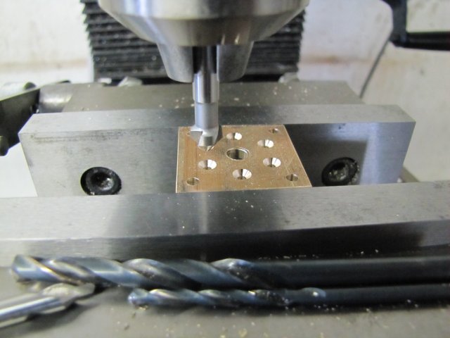
The 6mm hole in the middle is NOT on the plans - actually there's supposed to be a 1/2" boss (or for my metric build a 12mm one) there... I was just being my lazy self...
A quick job on the lathe to turn up a bit of brass with a 6mm diameter protrusion to fit the hole in the last part, and 12mm to fit the cylinder bore:
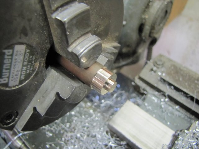
That was parted off leaving a 0.6mm "flange" and then I just soft-soldered it to the brass mounting plate - seen from the bottom:
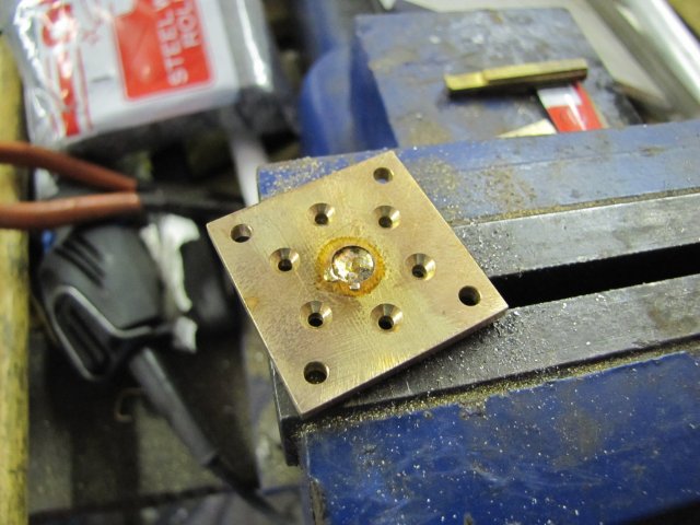
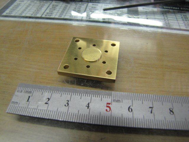
All done:
On to tapping the cylinder. I don't dislike tapping, but it can be a bit of a chore and requires attention and a good feel to avoid heartache. As always for aluminium, I use methylated spirits as tapping fluid, and as there was 16 holes to tap three times over on each, 48 operations in total, I just decanted some meths into a bottle cap to swash the tap in after each hole to clean off swarf and lubricate it:
It's a real pleasure to plonk six screws into a bolt circle, and just tighten them down. I've made parts in the past and successfully done this without having to fiddle about enlarging a hole here & there, but with using the DRO this was even easier... Plonk in screws & tighten up. QED.:
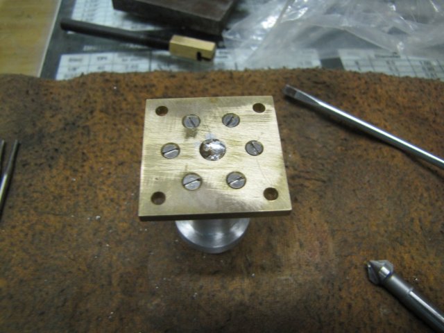
Even the valve chest screws fit like a glove:
: And NO - I won't be using those cheese-head screws on the finished engine! - To paraphrase a certain Mr. Yoda: Horrible look, they do...
So much for today's bit then. More when I get a round tuit
Regards, Arnold
I'm glad that you're finding this useful. If you do have any questions please fire away; it helps other people too. I'm just blundering along in my own style, so it's not necessarily right or the best way. Everybody's welcome to chip in with ideas and suggestions.:big: I might complain about Namibian winters, but they are much more like the Aussie ones. And no thick layers of white stuff on the ground either; I've only ever touched snow once in my life, and seen it in real life from a distance about 5 times. The only downside is the humidity here; today it was nice and humid, and right now as I'm posting, it's a whopping big 33%. Later in the week that will most likely drop to about 20% - and then people wonder why Namibians drink a lot ;D
Not much done today, but some progress none-the-less.
A bit of 25mm round aluminium bar turned for the face of the inboard cylinder head, and drilled through at 3.2mm:

The 3.2mm is for the 1/8" brazing rod that I'm going to use as the piston rod. That's quite a bit thicker than the 3/32" the plans call for. I have 2mm and 3.2mm rod available, and while I could knock up a box tool to turn the 1/8" rod down to 2.4mm (~3/32"), the engine might actually look better with the thicker rod, even though it would impair performance slightly on the down-stroke by the loss of upper cylinder volume.
Even though this thread is as much about getting to grips with the DRO as it is about building an engine, for the next step I reverted back to what I know well and do fairly quickly. So, chuck unmounted from the lathe - workpiece-and-all - and re-mounted on the rotary table on the mill. I just used the 3.2mm drill chucked up in reverse in the mill chuck to center the RT to the spindle, and zeroed the DRO on that:

Then I just dialed in the 9.525mm PCD offset on the Y axis (3/4" ~19.05mm - halve of that = 9.525mm) and used the RT to index the holes for drilling:

Back to the lathe, and then drilled 4.2mm part-way and tapped M5 for the packing nut, and then I started parting away. The cylinder head needs a small boss on the back side, and I just used a pair of calipers to check for size:

Inboard head done:

Next up, the outboard head. I don't know if I'm starting to turn into a grumpy old man and getting pedantic, or just plain having fun in my own perverse personal way, but thinking through the looks of the engine and what I'd like as an end result, I thought it would be nice to make the outboard head in brass to contrast a bit with the aluminium cylinder and base. So I squared up a bit of 1/8" (3.2mm) brass plate:
Then I clamped it up on the mill and poked a lot of holes in it. I coordinate drilled the 3mm mounting holes on the outside corners, and used the DRO's PCD function to drill the cylinder mounting holes. I got a nice surprise there; when I switched the DRO to PCD mode, it actually remembered the last settings I entered, which was when I drilled the cylinder block's holes. Instant time-saver and really nifty ;D:

The 6mm hole in the middle is NOT on the plans - actually there's supposed to be a 1/2" boss (or for my metric build a 12mm one) there... I was just being my lazy self...
A quick job on the lathe to turn up a bit of brass with a 6mm diameter protrusion to fit the hole in the last part, and 12mm to fit the cylinder bore:

That was parted off leaving a 0.6mm "flange" and then I just soft-soldered it to the brass mounting plate - seen from the bottom:

All done:

On to tapping the cylinder. I don't dislike tapping, but it can be a bit of a chore and requires attention and a good feel to avoid heartache. As always for aluminium, I use methylated spirits as tapping fluid, and as there was 16 holes to tap three times over on each, 48 operations in total, I just decanted some meths into a bottle cap to swash the tap in after each hole to clean off swarf and lubricate it:

It's a real pleasure to plonk six screws into a bolt circle, and just tighten them down. I've made parts in the past and successfully done this without having to fiddle about enlarging a hole here & there, but with using the DRO this was even easier... Plonk in screws & tighten up. QED.:

Even the valve chest screws fit like a glove:

:
And NO - I won't be using those cheese-head screws on the finished engine! - To paraphrase a certain Mr. Yoda: Horrible look, they do...So much for today's bit then. More when I get a round tuit
Regards, Arnold


arnoldb
Well-Known Member
- Joined
- Apr 8, 2009
- Messages
- 1,792
- Reaction score
- 12
Thanks Darren - I don't mind.
Very nice model Thm:; I like the "chuffer" you added to the exhaust. Actually that reminded me - I must still tap the exhaust hole on mine as I want to add pipework to it for running on live steam at a later stage
Tomorrow's a public holiday here, so I might get to make some more bits for a change ;D
Kind regards, Arnold
- I don't mind.Very nice model Thm:; I like the "chuffer" you added to the exhaust. Actually that reminded me - I must still tap the exhaust hole on mine as I want to add pipework to it for running on live steam at a later stage
Tomorrow's a public holiday here, so I might get to make some more bits for a change ;D
Kind regards, Arnold
Arnold,
A working 'chuffer'
http://www.homemodelenginemachinist.com/index.php?topic=536.0
Glad you are putting your own stamp on this engine rather than following plans religiously. :bow: :bow:
John
A working 'chuffer'
http://www.homemodelenginemachinist.com/index.php?topic=536.0
Glad you are putting your own stamp on this engine rather than following plans religiously. :bow: :bow:
John
arnoldb
Well-Known Member
- Joined
- Apr 8, 2009
- Messages
- 1,792
- Reaction score
- 12
John, thank you - I knew I'd seen your "chuffer" somewhere - that's a definite to "play" with in future. And thank you; yes I'm adapting the plans to my own taste, available materials and equipment. All the critical measurements are the same as on the plans though. With each Elmer engine I'm building, I'm gaining even more respect for Mr.Verburg. I'm sure he could have "dollied" up all the engines like I'm doing now and you've done, but I think he on purpose left them simple to build for newcomers to the hobby. There's only three or four engines in his book that I wouldn't advise for a first or second engine build.
Thanks Vince I'm enjoying the new toy ;D. I don't know about the easy part though; it does require a bit of effort. The basic machining is easy - that wasn't the case three years ago though, so maybe I've learnt a bit along the line. Attempting good finishes remains a lot of hard work though
Some bits done today...
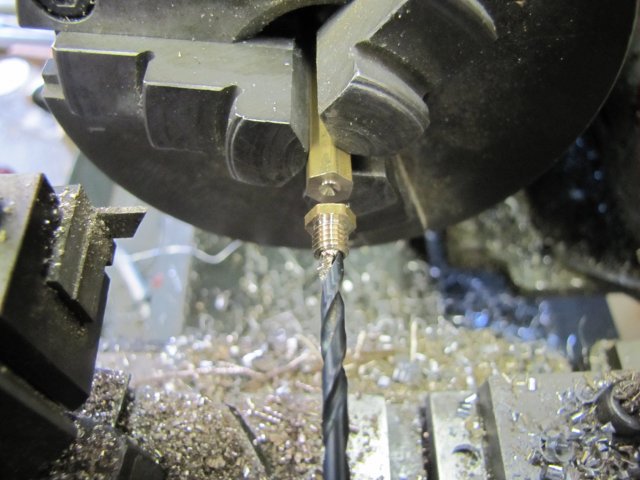
I started of with some 6mm hex brass rod for the two packing nuts. From difficulties I encountered on other builds, I learnt that it's better to first turn down and thread the needed section, put in the threading undercut after that, and only after that was done drill through and part off. I've found that if one first drill the central hole through, the action of the threading nut tends to reduce the hole diameter. If the thread run-out undercut is made before hand on these small pieces, it's very easy to break off the section being threaded, as the threading operation places quite a bit of torque on the workpiece.
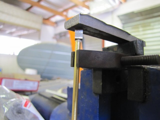
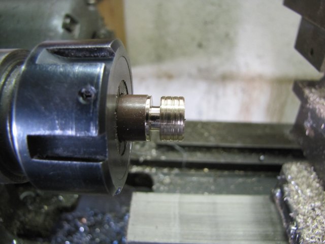
So I first turned it down to 5mm and threaded with the tailstock die holder:
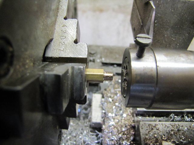
And then put the thread run-out groove in using the parting tool, drilled through, and parted off, using the drill to catch the piece:
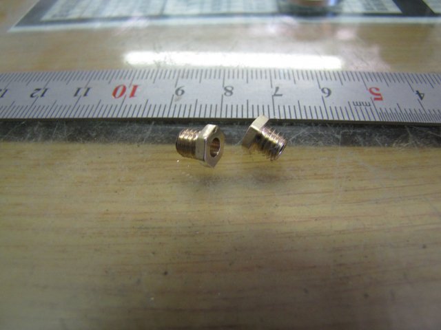
The second packing nut followed - same process - and after some elbow grease to tidy them up, they were done:
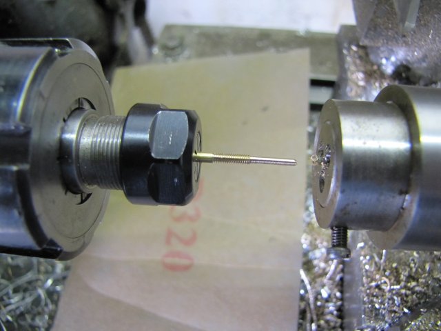
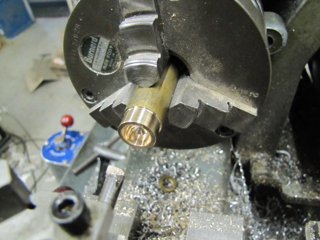
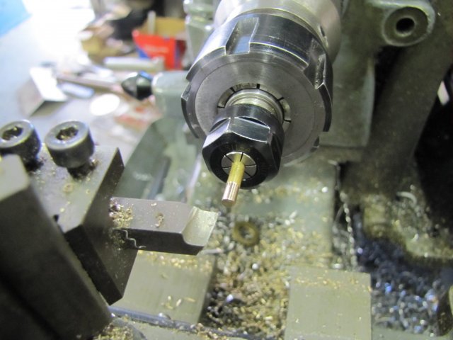
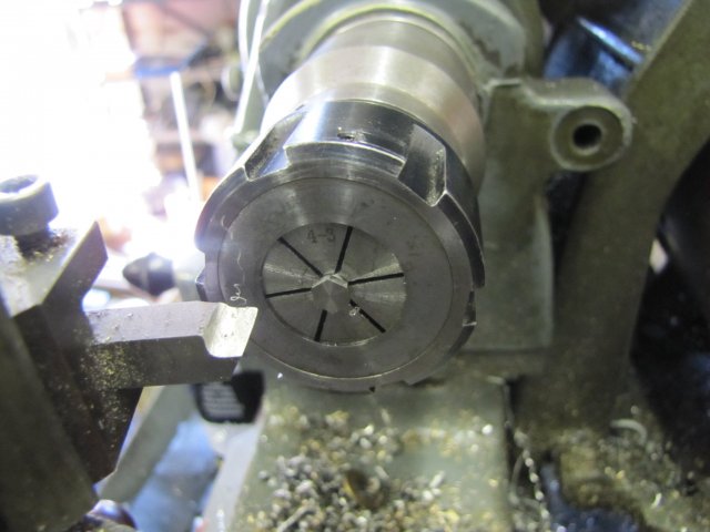
On to some fiddly work next; the valve rod. As has become usual for me, I made it up of two bits - a bit of 2mm rod turned down and threaded as needed, and a separate bit for the eccentric rod end. Some 2mm brazing rod turned down to 1.5mm for 8mm - with the little ER11 collet chuck gripped in the lathe's ER25 chuck:

Turning thin bits like this can be problematic; the toolbit needs to be honed sharp enough to easily cut a tough steak, positioned dead on lathe center line, the radius on the toolbit needs to be small - so as to keep the area in contact with the workpiece to a minimum, and the cut made to depth in one pass, so that most of the cutting action is on the left hand side of the toolbit rather than on the front of it. Well, that's my theory anyway.
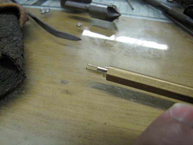
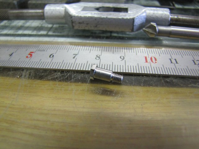
Next up some threading... And that ruined a bit of the carefully turned section from the last photo :-[ I moved the workpiece a bit more out of the chuck to get to the section to thread. I forgot to add a bit of taper lead-in for the M2 die though, and as a result it didn't "catch" immediately on this tough bronze rod when I started threading, and ruined a section of the previously turned section. The tail end bit is still fairly smooth and parallel, so will work fine as the guide in the steam chest:
If you click on the last two photos, you can see more of the gory detail.
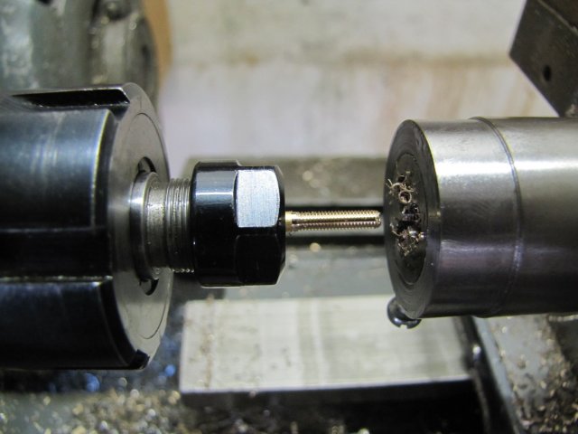
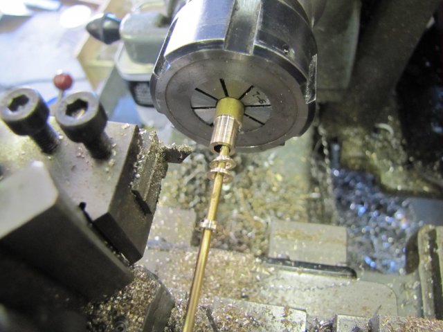
While I was set up for cutting the M2 threads, I did a bit more; I've been running out of M2 threaded rod, so I made up some more. The previous threads were done manually; I turned the chuck by hand. To make threaded rod, that would be tiring to say the least, so for longer threaded sections, I just start off with a bit of rod and the tailstock die holder for support to get it started. With the lathe at it's lowest non-back gear speed (200 RPM) and plenty of cutting fluid, I do this under power. The M2 threads are fairly fine, so it takes a while to run through the section. Once the die holder leaves the tailstock support, I just guide it by hand, adding cutting fluid all the way:
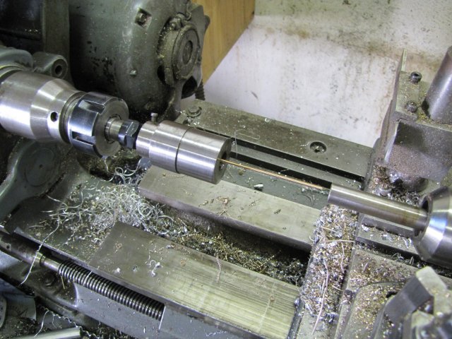
When close to the chuck, I stop the lathe, and reverse it to get the section off.
A couple of minutes' work, and I have some more threaded rod:
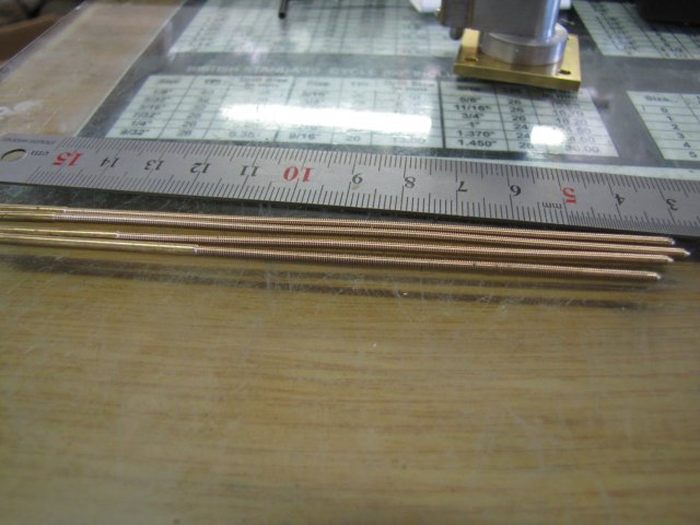
The torque of threading does distort the rods somewhat, but they are good enough to use as fasteners on short sections.
Next up, two 2mm nuts screwed on each section (the short sections are what I had left), and a dab of thread retainer on the end of each section:
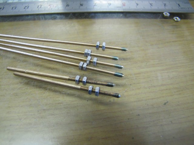
The sections screwed into the cylinder - with the head in place:
After a couple of minutes or ten, I screwed the bottom nuts down to retain the cylinder head properly, and lightly screwed down the top nuts to those. Then with my small and sharp and trusty electronics side-cutter, I clipped off the rods level to the top nuts. The cutter is upside-down in the photo:
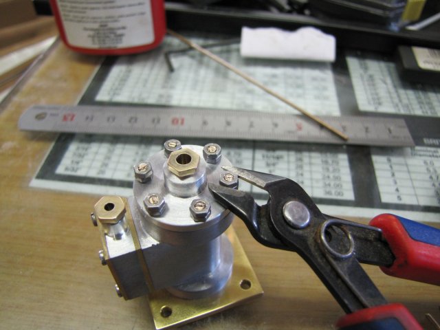
The top nuts do two things - They add enough length to the studs as I'm going to make up slightly thicker nuts than the single nuts used used so far - purely for looks - and they also remove burrs from the threads left after clipping off the rods, ensuring that later on nuts can easily be screwed back on. After removing the top nuts, I filed the studs down a bit to get rid of the cutting marks:
After that, I built a bit of a booboo - things were just going too well :big: - I got a measurement out of kilter while making up the eccentric rod end for the valve rod:
Not good enough, so a re-do was in order.
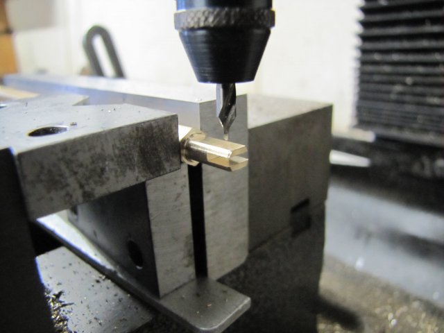
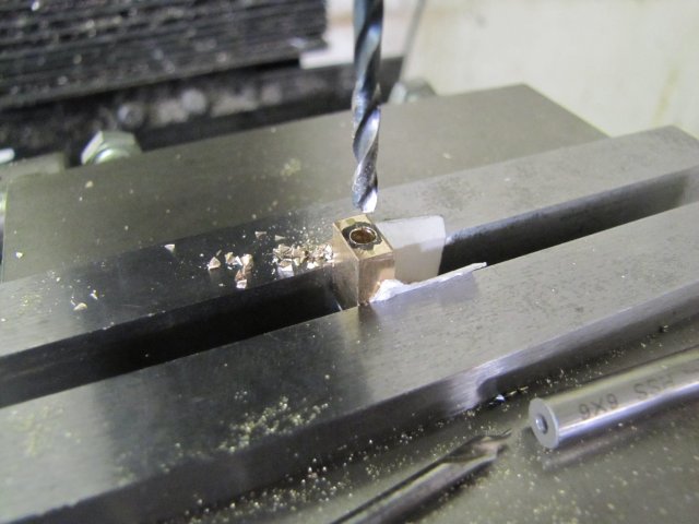
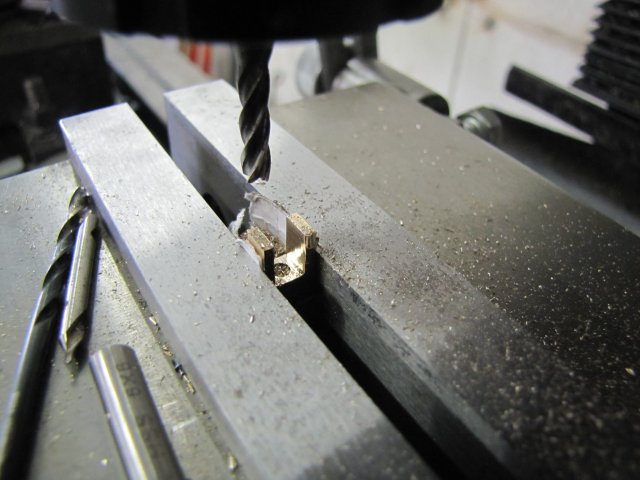
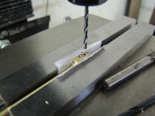
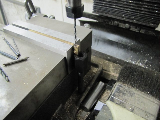
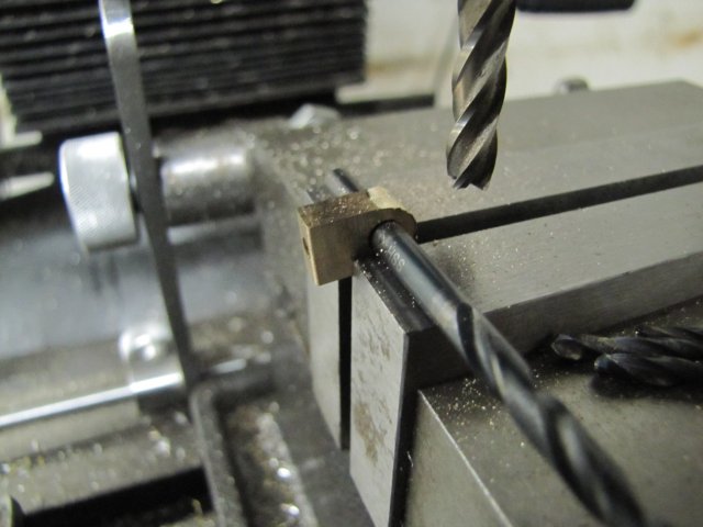
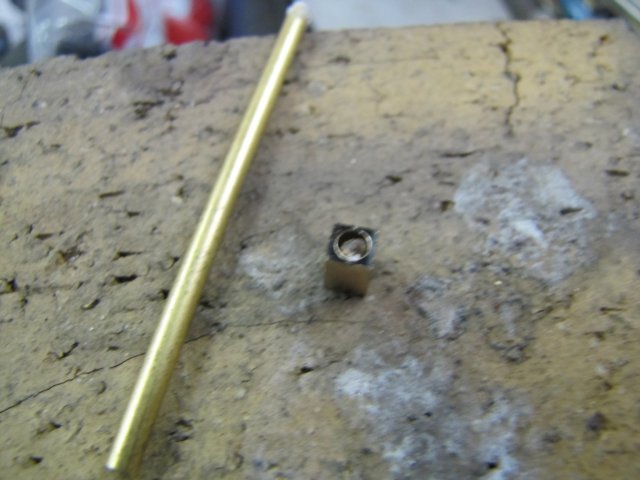
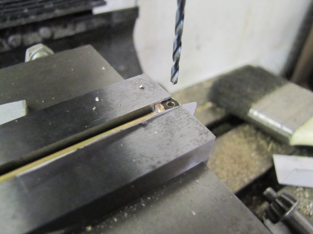
On to the re-do, and this time the cut-outs were in place, so I just got ready to spot it for cross-drilling 1.5mm:
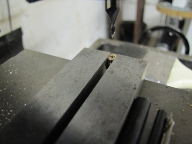
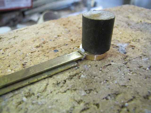
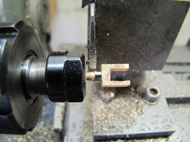
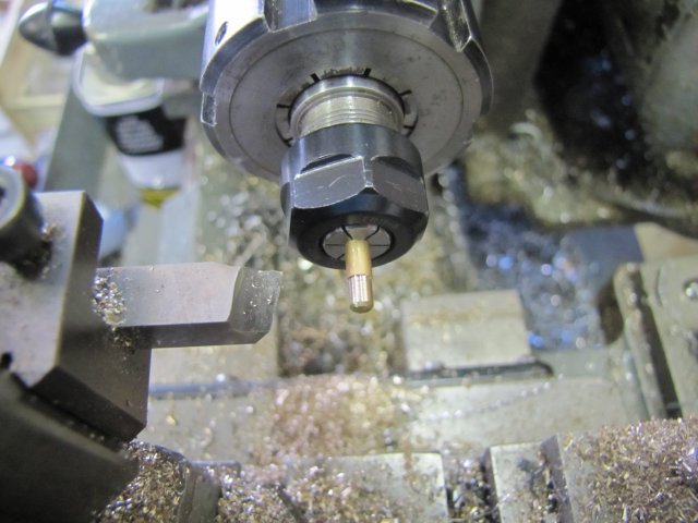
After parting off the eccentric rod end from the parent stock, I poked a 1.8mm deep 2mm hole into its back side with a center cutting slot mill:
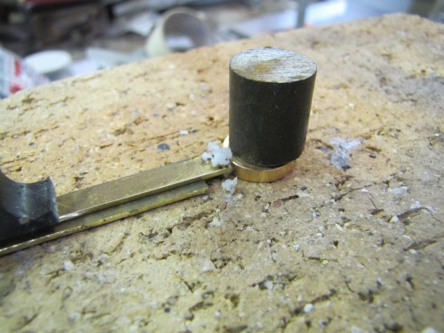
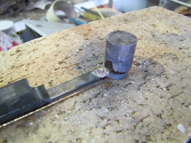
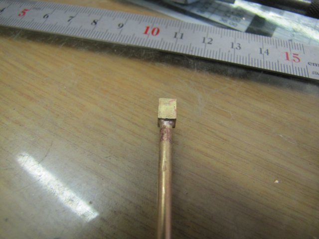
With the previously made valve rod shortened appropriately, I proceeded to solder it into the eccentric rod end:
Just ordinary electronics soft solder; the valve rod should never see high loads put on it.
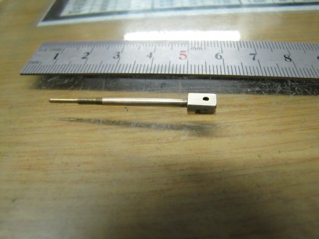
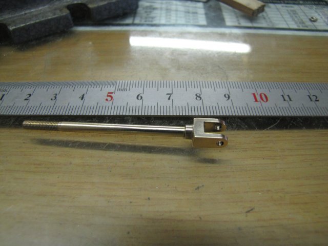
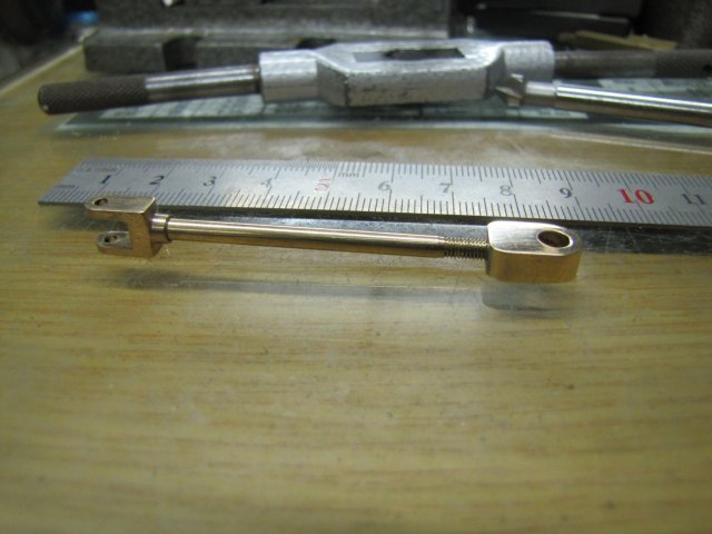
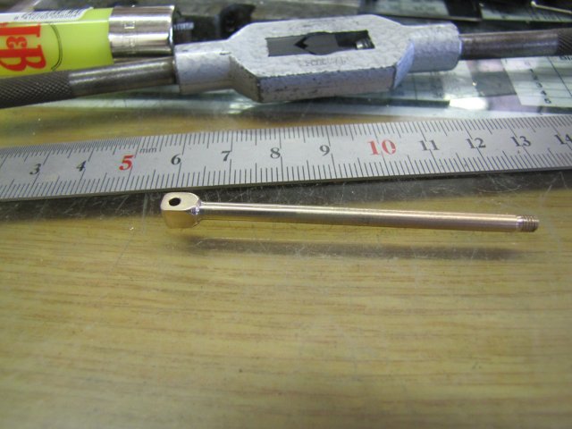
Completed valve rod - not a stirling piece of engineering, but good enough for me for now:
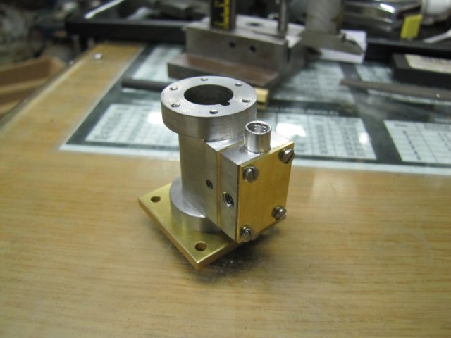
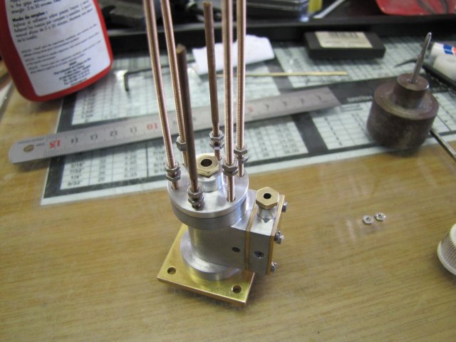
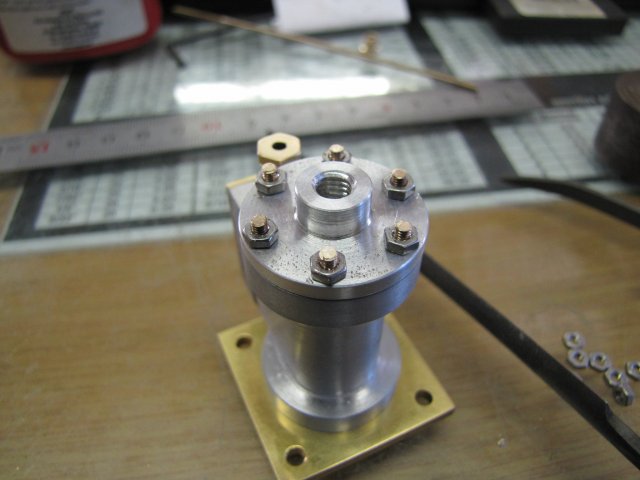
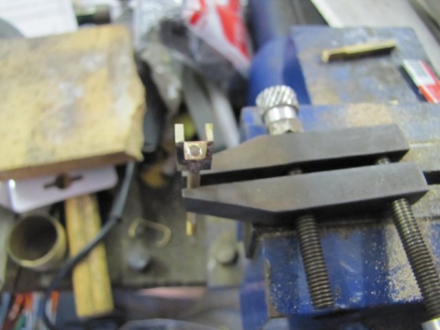
In between, the steam chest received the same threaded rod treatment as the cylinder head, and as a parting shot for today's work, things are starting to look a bit more interesting:

I have some 3mm and 4mm hex bar on order to make some nuts out of, but if it does not come in time (next 2 weeks or so), I guess I'll revert to filing down some rod to make suitable nuts from; the proportions of the nuts shown are just not right to my eye.
Regards, Arnold
- I knew I'd seen your "chuffer" somewhere - that's a definite to "play" with in future. And thank you; yes I'm adapting the plans to my own taste, available materials and equipment. All the critical measurements are the same as on the plans though. With each Elmer engine I'm building, I'm gaining even more respect for Mr.Verburg. I'm sure he could have "dollied" up all the engines like I'm doing now and you've done, but I think he on purpose left them simple to build for newcomers to the hobby. There's only three or four engines in his book that I wouldn't advise for a first or second engine build.Thanks Vince
I'm enjoying the new toy ;D. I don't know about the easy part though; it does require a bit of effort. The basic machining is easy - that wasn't the case three years ago though, so maybe I've learnt a bit along the line. Attempting good finishes remains a lot of hard work though Some bits done today...
I started of with some 6mm hex brass rod for the two packing nuts. From difficulties I encountered on other builds, I learnt that it's better to first turn down and thread the needed section, put in the threading undercut after that, and only after that was done drill through and part off. I've found that if one first drill the central hole through, the action of the threading nut tends to reduce the hole diameter. If the thread run-out undercut is made before hand on these small pieces, it's very easy to break off the section being threaded, as the threading operation places quite a bit of torque on the workpiece.
So I first turned it down to 5mm and threaded with the tailstock die holder:
And then put the thread run-out groove in using the parting tool, drilled through, and parted off, using the drill to catch the piece:
The second packing nut followed - same process - and after some elbow grease to tidy them up, they were done:
On to some fiddly work next; the valve rod. As has become usual for me, I made it up of two bits - a bit of 2mm rod turned down and threaded as needed, and a separate bit for the eccentric rod end. Some 2mm brazing rod turned down to 1.5mm for 8mm - with the little ER11 collet chuck gripped in the lathe's ER25 chuck:

Turning thin bits like this can be problematic; the toolbit needs to be honed sharp enough to easily cut a tough steak, positioned dead on lathe center line, the radius on the toolbit needs to be small - so as to keep the area in contact with the workpiece to a minimum, and the cut made to depth in one pass, so that most of the cutting action is on the left hand side of the toolbit rather than on the front of it. Well, that's my theory anyway.
Next up some threading... And that ruined a bit of the carefully turned section from the last photo :-[ I moved the workpiece a bit more out of the chuck to get to the section to thread. I forgot to add a bit of taper lead-in for the M2 die though, and as a result it didn't "catch" immediately on this tough bronze rod when I started threading, and ruined a section of the previously turned section. The tail end bit is still fairly smooth and parallel, so will work fine as the guide in the steam chest:

If you click on the last two photos, you can see more of the gory detail.
While I was set up for cutting the M2 threads, I did a bit more; I've been running out of M2 threaded rod, so I made up some more. The previous threads were done manually; I turned the chuck by hand. To make threaded rod, that would be tiring to say the least, so for longer threaded sections, I just start off with a bit of rod and the tailstock die holder for support to get it started. With the lathe at it's lowest non-back gear speed (200 RPM) and plenty of cutting fluid, I do this under power. The M2 threads are fairly fine, so it takes a while to run through the section. Once the die holder leaves the tailstock support, I just guide it by hand, adding cutting fluid all the way:
When close to the chuck, I stop the lathe, and reverse it to get the section off.
A couple of minutes' work, and I have some more threaded rod:

The torque of threading does distort the rods somewhat, but they are good enough to use as fasteners on short sections.
Next up, two 2mm nuts screwed on each section (the short sections are what I had left), and a dab of thread retainer on the end of each section:
The sections screwed into the cylinder - with the head in place:
After a couple of minutes or ten, I screwed the bottom nuts down to retain the cylinder head properly, and lightly screwed down the top nuts to those. Then with my small and sharp and trusty electronics side-cutter, I clipped off the rods level to the top nuts. The cutter is upside-down in the photo:
The top nuts do two things - They add enough length to the studs as I'm going to make up slightly thicker nuts than the single nuts used used so far - purely for looks - and they also remove burrs from the threads left after clipping off the rods, ensuring that later on nuts can easily be screwed back on. After removing the top nuts, I filed the studs down a bit to get rid of the cutting marks:
After that, I built a bit of a booboo - things were just going too well :big: - I got a measurement out of kilter while making up the eccentric rod end for the valve rod:
Not good enough, so a re-do was in order.
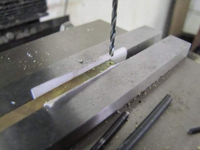
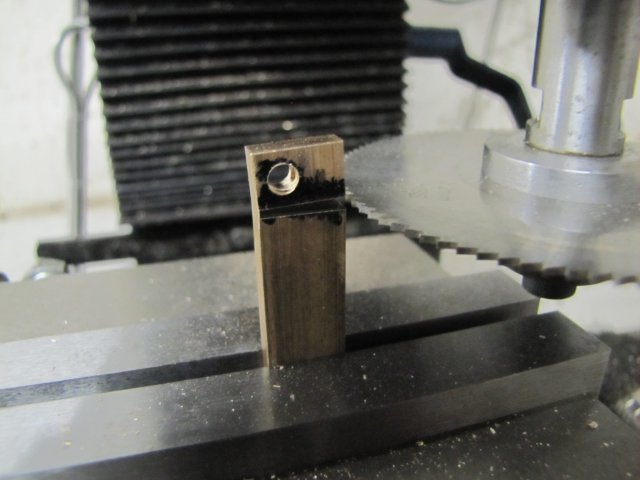
On to the re-do, and this time the cut-outs were in place, so I just got ready to spot it for cross-drilling 1.5mm:
After parting off the eccentric rod end from the parent stock, I poked a 1.8mm deep 2mm hole into its back side with a center cutting slot mill:
With the previously made valve rod shortened appropriately, I proceeded to solder it into the eccentric rod end:
Just ordinary electronics soft solder; the valve rod should never see high loads put on it.
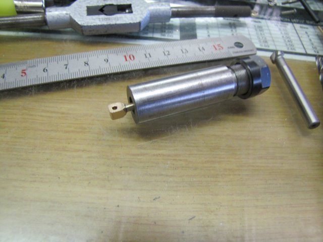
Completed valve rod - not a stirling piece of engineering, but good enough for me for now:
In between, the steam chest received the same threaded rod treatment as the cylinder head, and as a parting shot for today's work, things are starting to look a bit more interesting:

I have some 3mm and 4mm hex bar on order to make some nuts out of, but if it does not come in time (next 2 weeks or so), I guess I'll revert to filing down some rod to make suitable nuts from; the proportions of the nuts shown are just not right to my eye.
Regards, Arnold
arnoldb
Well-Known Member
- Joined
- Apr 8, 2009
- Messages
- 1,792
- Reaction score
- 12
This morning I awoke to the phone ringing - with a sagging heart I thought it's one of my work sites that have a problem, but that soon turned to joy. It was my dad informing me that I'm now the owner of a well-kitted tool & cutter grinder - Thanks Dad !! I just have to figure out a way to get it the 2000km from South Africa to here in Windhoek. On Monday some phone lines will be turning warm ;D
For the shop session today, I started on the eccentric. In the first post of this thread I mentioned that I want to kit the engine out with a slip eccentric, so I sat down and did a rough sketch of how it should go together. The bit of mystery metal is what the bits will be made from:
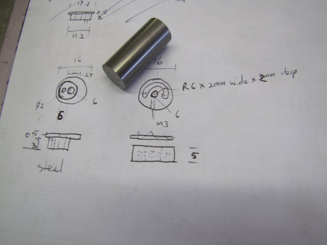
The bit of "mystery" metal is only unknown to me in terms of precisely what kind of alloy it is. What I do know about it, however, more than makes up for the unknown and makes it really suitable for the use it's going to be put to:
* It's from a dot matrix printer head bearing shaft - and the print head assembly used to run on bronze or oilite bushes on it - so it's a good bearing metal in combination with bronze. Pretty wear resistant as well.
* I have a bunch of these shafts, some of them sat outside in the rain, and it appears the are pretty rust resistant.
* Last but not least, I know this stuff machines like an absolute dream and gives great finishes.
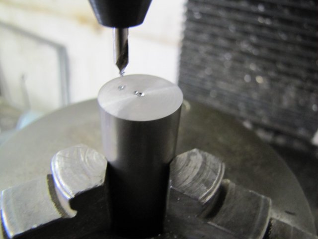
After facing the saw-marks off the steel, I centered the rotary table under the mill spindle, transferred the chuck to it, and spotted three locations - center, eccentric offset, and the position for the eccentric engagement pin:
Before I spotted the engagement pin location, the 6mm offset I noted for it on my drawing looked a bit too much, so I used 5mm rather than 6mm for it's offset. I can't even keep to my own plans :big:
Then I drilled a 2mm hole 3mm deep into the workpiece for the pin:
Back to the lathe, and this time with the four-jaw chuck, I centered up on the eccentric offset:
And turned the eccentric to 11.2mm diameter:
Next I centered the workpiece, turned the outside diameter down to size, and center drilled, drilled 5.9mm and reamed to 6mm:
Reaming was not done under power; I turned the chuck by hand - a good bit of exercise for an office dweller
A quick part-off - old broken end mills make great workpiece catchers :
You might notice I forgot to smooth off the burr raised by the parting tool - that came back and bit me a bit later - literally. I happened to pass my left index finger over it later on, and it released some red stuff :
After parting off the "slip" side of the eccentric, I faced the the remaining stock, leaving about a 1mm boss 0.4mm thick in the center. That's not on my sketch, but with a basic understanding of how a slip eccentric works, I added that to minimize friction:
Back to the rotary table on the mill, and I milled the needed slot with a 2mm slot drill:
After parting that lot off on the lathe, the last step was to drill 2.5mm for an M3 grub screw:
With a bit of 2mm diameter music wire fitted - secured with high-strength retainer - the eccentric bits were done:

For a final process today, I started on the eccentric strap - nowhere close to the original plans here - Just some bronze turned down and bored for the job, and parted off:
Fits on the eccentric like a glove. Some more work required on that bit though...
Hopefully more tomorrow ;D
Kind regards, Arnold
For the shop session today, I started on the eccentric. In the first post of this thread I mentioned that I want to kit the engine out with a slip eccentric, so I sat down and did a rough sketch of how it should go together. The bit of mystery metal is what the bits will be made from:
The bit of "mystery" metal is only unknown to me in terms of precisely what kind of alloy it is. What I do know about it, however, more than makes up for the unknown and makes it really suitable for the use it's going to be put to:
* It's from a dot matrix printer head bearing shaft - and the print head assembly used to run on bronze or oilite bushes on it - so it's a good bearing metal in combination with bronze. Pretty wear resistant as well.
* I have a bunch of these shafts, some of them sat outside in the rain, and it appears the are pretty rust resistant.
* Last but not least, I know this stuff machines like an absolute dream and gives great finishes.
After facing the saw-marks off the steel, I centered the rotary table under the mill spindle, transferred the chuck to it, and spotted three locations - center, eccentric offset, and the position for the eccentric engagement pin:
Before I spotted the engagement pin location, the 6mm offset I noted for it on my drawing looked a bit too much, so I used 5mm rather than 6mm for it's offset. I can't even keep to my own plans :big:
Then I drilled a 2mm hole 3mm deep into the workpiece for the pin:
Back to the lathe, and this time with the four-jaw chuck, I centered up on the eccentric offset:
And turned the eccentric to 11.2mm diameter:
Next I centered the workpiece, turned the outside diameter down to size, and center drilled, drilled 5.9mm and reamed to 6mm:
Reaming was not done under power; I turned the chuck by hand - a good bit of exercise for an office dweller
A quick part-off - old broken end mills make great workpiece catchers :
You might notice I forgot to smooth off the burr raised by the parting tool - that came back and bit me a bit later - literally. I happened to pass my left index finger over it later on, and it released some red stuff :
After parting off the "slip" side of the eccentric, I faced the the remaining stock, leaving about a 1mm boss 0.4mm thick in the center. That's not on my sketch, but with a basic understanding of how a slip eccentric works, I added that to minimize friction:
Back to the rotary table on the mill, and I milled the needed slot with a 2mm slot drill:
After parting that lot off on the lathe, the last step was to drill 2.5mm for an M3 grub screw:
With a bit of 2mm diameter music wire fitted - secured with high-strength retainer - the eccentric bits were done:
For a final process today, I started on the eccentric strap - nowhere close to the original plans here - Just some bronze turned down and bored for the job, and parted off:
Fits on the eccentric like a glove. Some more work required on that bit though...
Hopefully more tomorrow ;D
Kind regards, Arnold
arnoldb
Well-Known Member
- Joined
- Apr 8, 2009
- Messages
- 1,792
- Reaction score
- 12
Thanks Brian - & it's a pleasure
Stew, thank you Hmmm... Sounds like we might be in for another Potty Engineering special; I can't wait ;D
: Well, zero progress for me today; I felt in an extremely lazy mood today - so rather than go to the shop and build junk parts, I just lazed around.
At least we have another long-weekend coming up next weekend, and hopefully the material I've ordered will be here in time for that.
Kind regards, Arnold
Stew, thank you
Hmmm... Sounds like we might be in for another Potty Engineering special; I can't wait ;D:
Well, zero progress for me today; I felt in an extremely lazy mood today - so rather than go to the shop and build junk parts, I just lazed around.At least we have another long-weekend coming up next weekend, and hopefully the material I've ordered will be here in time for that.
Kind regards, Arnold
arnoldb
Well-Known Member
- Joined
- Apr 8, 2009
- Messages
- 1,792
- Reaction score
- 12
A bit of progress today. The build is now on the fiddly parts stage - making up all the linkages and so on. On plans these look easy, but they take a lot of time to make - for a good runner they need a good bit of accuracy.
The plans mostly call for 1/16" (1.6mm) brass plate for many of the linkages, but I only have 2mm and 1.2mm available - so I'll be using the 1.2mm plate and compensating for the thickness difference where needed. For a start, two ruler-wide strips sawn off the big bit of stock I have:
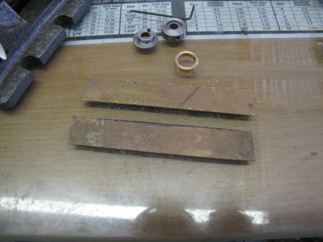
I felt like a bit of exercise, so filed one edge of one piece nice and straight:
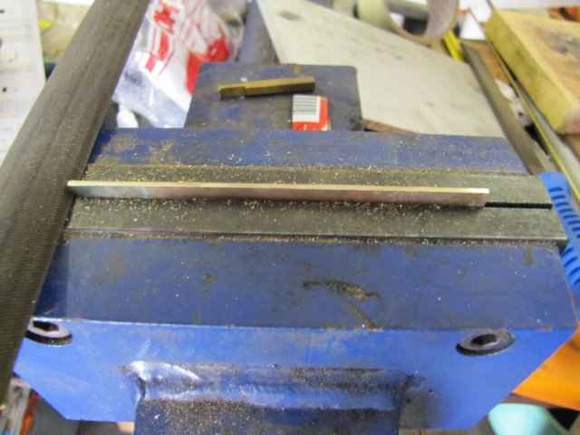
Then I marked the strip for the eccentric rod, sawed to just over size and filed it down, and then filed a curve on the end to match the ring I turned up for the eccentric last Saturday. It's nice to file a fitting curve that's also shaped well enough that the ring can just sit on top of it:
Then I drilled the hole for the connection to the valve rod - I decided to make the pin size a bit bigger - 2mm instead of the 1.6mm:
The valve rod's hole will have to be enlarged as well, but that's not a problem.
On to a bit of silver soldering - things located with some flux and a sliver of silver solder plate on top:
A bit more flux added to protect the silver solder sliver:
And a quick showing-of-the-torch and cooling down. The job looks horrible here:
Into the citric acid pickle. The level in my pickle container was running a bit low, so I popped into the kitchen for some boiling water from the kettle (that also made a nice cup of coffee). The addition of hot water makes the pickling job go faster, and I just plonked it down on top of the firebrick with a piece of aluminium to distribute and use of the latent heat left in the fire brick:
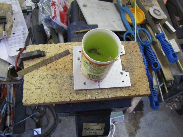
The pickle has been used a bit, that's why it's starting to turn green - from the copper dissolved in it.
By the time my coffee was finished, the pickle had also done its job - and things were looking a bit better:
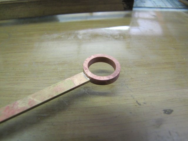
After a bit of clean-up, the eccentric rod looks OK:
As you can see, the bronze ring looks - and is - very copper coloured. I've noticed this in the past as well after silver soldering and pickling, and I have a hunch its because the zinc in the bronze starts to evaporate at silver soldering temperatures, while the pickle might also leach it out of the copper. I didn't want to fuss around too much and remove a lot of material from the workpiece though, as it was pretty close to final size already. This is something I'll have to keep in mind for future builds.
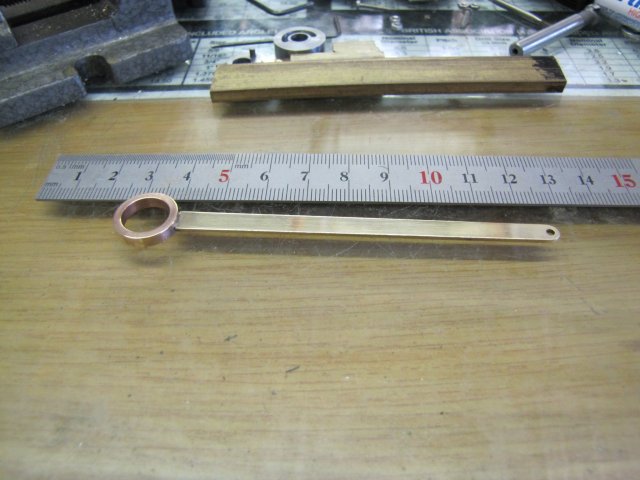
A quick trial fit, and a problem : :
The eccentric rod is a whole 1mm too long... I traced that back to a calculation error, but fortunately I won't have to re-make any parts to fix the problem; the valve rod has enough length and available play to it to shorten it by 1.5mm to ensure adequate clearance. As stated earlier, the smaller holes in the valve rod is not a problem; those will be opened up to 2mm to match the eccentric rod.
On to the connecting rod, and a start on the fork from a bit of 4.6x8x11.2mm sized brass - here drilled through 3mm:
Next I milled a 7.1mm deep x 4.6mm wide slot through it:
A 4mm cutter works well here; mill down to depth on the center line in 2mm steps, and then clean up the sides to width - makes the slot come out very nice.
I might get lynched or laughed at for what I'm going to say next, but I'm going to do it anyway.
Often times I notice posts where machinists are chasing extremely close tolerances on chucks and collets, and then are disgusted that the "cheap" items they buy are out by quite a bit. I know there are very close tolerance kit out there - at a premium - and if I'd bought one of the premium kits I'd be disgusted as well. My budget simply does not extend to the premium tools, so I have to make do with the less accurate and affordable stuff.
When I make my own kit, I try and do it as accurately as possible - as I have done with several collet chucks - but once I add the budget collets I can afford to it, a lot of that accuracy goes down the drain. Well, rather than fight an impossible battle, one can use a bit of run-out in one bit to minimise run-out in another bit. Nowhere perfect, but it helps. The one 16mm ER25 collet I have has an eccentric run-out of about 0.05mm close to the chuck, and the 3.5mm ER11 collet I have has an eccentric run-out of about 0.04mm. If the two are combined, and the run-outs set 180o apart, that leaves just a 0.01mm (0.0005") run-out on the workpiece close to the chuck, and I can easily and fairly accurately skim a bit of 3.2mm brazing rod down to 3mm while maintaining a fair modicum of accuracy:
Sometimes even the weak points of tools can be used to advantage
The same bit of 3.2mm rod flipped, turned down to 3mm, and threaded M3:
Another bit of silver soldering - please excuse the out-of-focus photo :-[:
I could have soft-soldered the last joint, but there was some turning left to do on it, and I wanted the strength of a silver soldered joint. Very carefully and slowly, I used the sharply honed parting tool to skim the workpiece down:
With the rod in place and used to set up nice and square, it was easy to drill the 2mm cross-hole:
After a bit of rounding over with a file, and some elbow grease, the bit looked like this:
Next up, the big end connector. Not really hard to do, but when I started to drill 2.5mm for the M3 threaded hole, I noticed that the workpiece wanted to move downward; I'd forgotten to add some paper to prevent that, so I just used some bits from the mill clamping kit to make an impromptu screw-jack:
Dark photo - if you click on it, the detail should be better.
Rather than sawing off the workpiece from the parent stock on the band saw or with a hack saw, I just slit it off - not all the way through, but just till the workpiece started lifting:
Using the slitting saw meant I could get very close to final size with little surface finish needed, and by leaving the last bit attached, it was easy to just break it off. If I slit it all the way through, I would have had to hunt through the shop for the workpiece wherever the saw tossed it.
On the plans, this bit remains fairly rectangular, but I thought it might look better rounded over, so I did a couple of quick facets on it:
A bit more file & emery work, some tapping, and a bit of reaming, and the connecting rod was done:
: Well,not quite - it still needs a lock-nut.
Regards, Arnold
The plans mostly call for 1/16" (1.6mm) brass plate for many of the linkages, but I only have 2mm and 1.2mm available - so I'll be using the 1.2mm plate and compensating for the thickness difference where needed. For a start, two ruler-wide strips sawn off the big bit of stock I have:
I felt like a bit of exercise, so filed one edge of one piece nice and straight:
Then I marked the strip for the eccentric rod, sawed to just over size and filed it down, and then filed a curve on the end to match the ring I turned up for the eccentric last Saturday. It's nice to file a fitting curve that's also shaped well enough that the ring can just sit on top of it:
Then I drilled the hole for the connection to the valve rod - I decided to make the pin size a bit bigger - 2mm instead of the 1.6mm:
The valve rod's hole will have to be enlarged as well, but that's not a problem.
On to a bit of silver soldering - things located with some flux and a sliver of silver solder plate on top:
A bit more flux added to protect the silver solder sliver:
And a quick showing-of-the-torch and cooling down. The job looks horrible here:
Into the citric acid pickle. The level in my pickle container was running a bit low, so I popped into the kitchen for some boiling water from the kettle (that also made a nice cup of coffee). The addition of hot water makes the pickling job go faster, and I just plonked it down on top of the firebrick with a piece of aluminium to distribute and use of the latent heat left in the fire brick:
The pickle has been used a bit, that's why it's starting to turn green - from the copper dissolved in it.
By the time my coffee was finished, the pickle had also done its job - and things were looking a bit better:
After a bit of clean-up, the eccentric rod looks OK:
As you can see, the bronze ring looks - and is - very copper coloured. I've noticed this in the past as well after silver soldering and pickling, and I have a hunch its because the zinc in the bronze starts to evaporate at silver soldering temperatures, while the pickle might also leach it out of the copper. I didn't want to fuss around too much and remove a lot of material from the workpiece though, as it was pretty close to final size already. This is something I'll have to keep in mind for future builds.
A quick trial fit, and a problem :
:
The eccentric rod is a whole 1mm too long... I traced that back to a calculation error, but fortunately I won't have to re-make any parts to fix the problem; the valve rod has enough length and available play to it to shorten it by 1.5mm to ensure adequate clearance. As stated earlier, the smaller holes in the valve rod is not a problem; those will be opened up to 2mm to match the eccentric rod.
On to the connecting rod, and a start on the fork from a bit of 4.6x8x11.2mm sized brass - here drilled through 3mm:
Next I milled a 7.1mm deep x 4.6mm wide slot through it:
A 4mm cutter works well here; mill down to depth on the center line in 2mm steps, and then clean up the sides to width - makes the slot come out very nice.
I might get lynched or laughed at for what I'm going to say next, but I'm going to do it anyway.
Often times I notice posts where machinists are chasing extremely close tolerances on chucks and collets, and then are disgusted that the "cheap" items they buy are out by quite a bit. I know there are very close tolerance kit out there - at a premium - and if I'd bought one of the premium kits I'd be disgusted as well. My budget simply does not extend to the premium tools, so I have to make do with the less accurate and affordable stuff.
When I make my own kit, I try and do it as accurately as possible - as I have done with several collet chucks - but once I add the budget collets I can afford to it, a lot of that accuracy goes down the drain. Well, rather than fight an impossible battle, one can use a bit of run-out in one bit to minimise run-out in another bit. Nowhere perfect, but it helps. The one 16mm ER25 collet I have has an eccentric run-out of about 0.05mm close to the chuck, and the 3.5mm ER11 collet I have has an eccentric run-out of about 0.04mm. If the two are combined, and the run-outs set 180o apart, that leaves just a 0.01mm (0.0005") run-out on the workpiece close to the chuck, and I can easily and fairly accurately skim a bit of 3.2mm brazing rod down to 3mm while maintaining a fair modicum of accuracy:
Sometimes even the weak points of tools can be used to advantage
The same bit of 3.2mm rod flipped, turned down to 3mm, and threaded M3:
Another bit of silver soldering - please excuse the out-of-focus photo :-[:
I could have soft-soldered the last joint, but there was some turning left to do on it, and I wanted the strength of a silver soldered joint. Very carefully and slowly, I used the sharply honed parting tool to skim the workpiece down:
With the rod in place and used to set up nice and square, it was easy to drill the 2mm cross-hole:
After a bit of rounding over with a file, and some elbow grease, the bit looked like this:
Next up, the big end connector. Not really hard to do, but when I started to drill 2.5mm for the M3 threaded hole, I noticed that the workpiece wanted to move downward; I'd forgotten to add some paper to prevent that, so I just used some bits from the mill clamping kit to make an impromptu screw-jack:

Dark photo - if you click on it, the detail should be better.
Rather than sawing off the workpiece from the parent stock on the band saw or with a hack saw, I just slit it off - not all the way through, but just till the workpiece started lifting:
Using the slitting saw meant I could get very close to final size with little surface finish needed, and by leaving the last bit attached, it was easy to just break it off. If I slit it all the way through, I would have had to hunt through the shop for the workpiece wherever the saw tossed it.
On the plans, this bit remains fairly rectangular, but I thought it might look better rounded over, so I did a couple of quick facets on it:
A bit more file & emery work, some tapping, and a bit of reaming, and the connecting rod was done:
:
Well,not quite - it still needs a lock-nut.Regards, Arnold
I was looking forward to see how you made the links and now I will have a lot less thinking to do. I guess there are many ways to approach the machining sequence but your methods are pretty direct. As for calculation errors, I have had a few of my own recently but the outcome was a remake.
Jan
Jan
arnoldb
Well-Known Member
- Joined
- Apr 8, 2009
- Messages
- 1,792
- Reaction score
- 12
Thank you Jim - sound's like I've set up some expectations to meet for myself then :big:
Thanks Jan. Yes, there are always many ways to do things - I tend to go for methods that are fairly straight forward to set up and does not waste too much raw material... The calculation errors will always be there; it's part of the fun ;D
Yesterday was a dead loss as far as the build goes; I paid some attention to domestic issues like fixing leaking toilets and taps, washing and polishing the car and some pleasant social interactions.
I love polished up brass cannon casings - don't ask me why; I just do. This is my tiny collection:
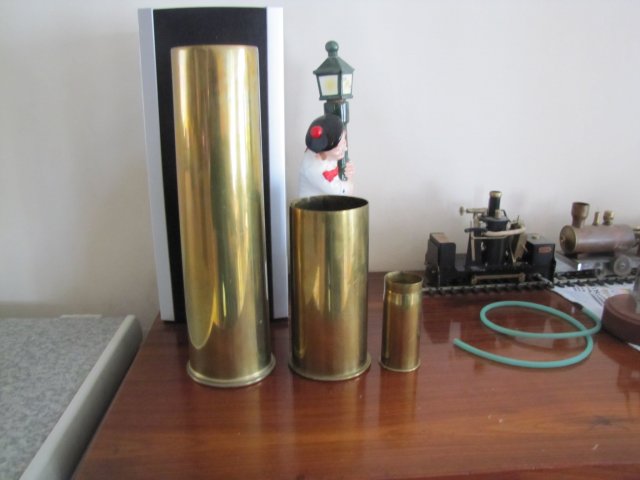
A couple of months ago, my one friend's father-in-law noticed these while on a visit, and yesterday evening as part of the aforementioned social interactions, that friend invited me over for a braai (BBQ/barbecue/barbie for folks in the rest of the world depending on where you are). Well his father-in-law was also invited, and upon arriving insisted that I open the Golf's boot - and then promptly plonked this one in there:
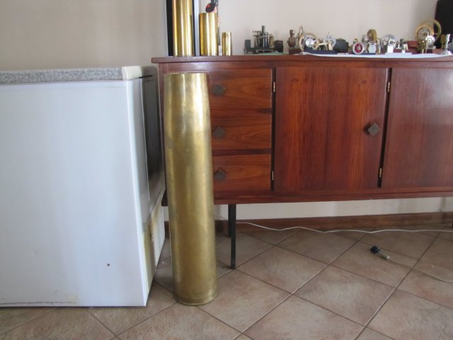
;D That's going to take a wee bit of work and a bit more to polish up! I haven't measured it yet, but it's about 1m long and looks to be about 140mm caliber, and has been safely discharged.
This morning I was awake nice and early - all bright-eyed and bushy tailed and looking forward to about eight hours of shop... Alas, that wasn't to be; we had a long power outage, so only a couple of hours in the shop.
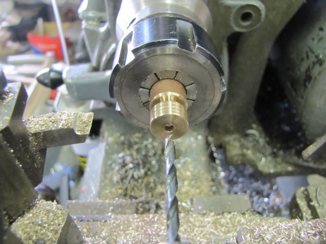
First off, the crank screw. Some 6mm stainless steel rod turned down as needed, and threaded and a tread run-out groove added:
On to the mill, and with the dividing head mounted in the vise, a hex head milled on it. I took a cue from Dr Jo's description on milling hex bits on bolts here to minimise the burr on the threaded side, and climb milled the hex. My mill's rigid enough for this kind of operation, and it worked a treat:
After parting off the screw (or perhaps more accurately bolt, since it won't be slotted) I faced the parted end off to tidy it up a bit:
All done, though the hex head needs some finishing still:
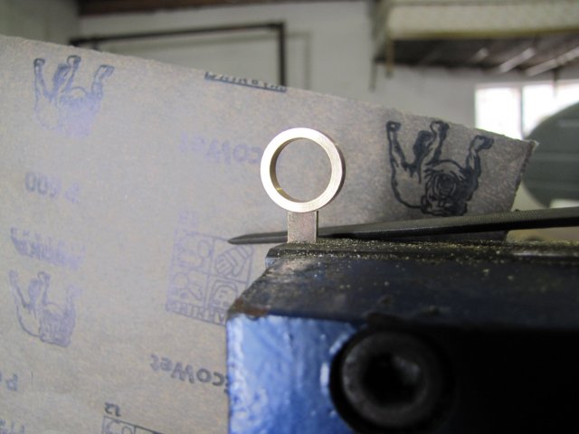
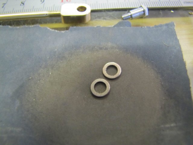
Next, some thin washers from brass - these are not on the plans, but I want to add them to minimise friction on the crank screw The first washer was too thick:
Getting rid of the burrs on the washers after parting off can be a bit of a pain-in-the-finger - I rubbed them down on some 320 emery:
The assembled crank screw and connecting rod with the washers:
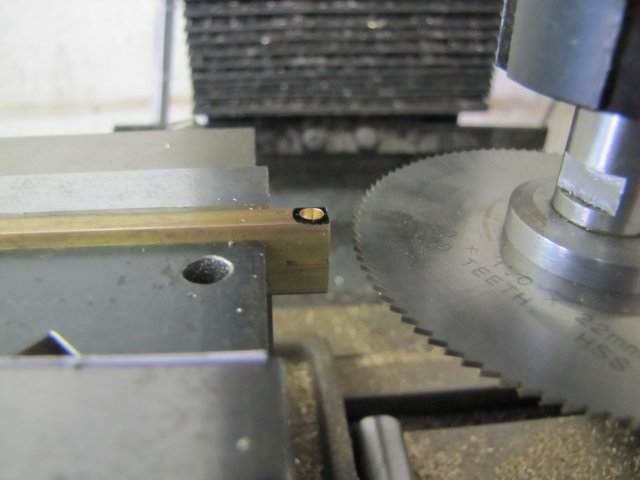
On to the piston rod. Some 4.7mm brass bar drilled 3.2mm to a depth of 3mm to accept some 3.2mm brazing rod, and slit at the needed length - in this case the workpiece length lying along the mill's Z axis:
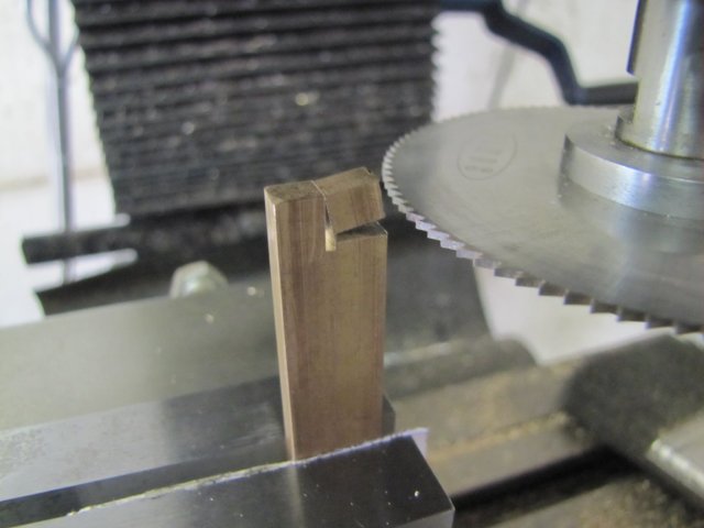
With the bit of stock set vertical in the vise, once again slit to just before final break-through:
A suitable bit of brazing rod - with the point filed down to approximate the drill bit cone, and nipped all around with a pair of electronics side-cutters to raise some burrs and make some grooves:
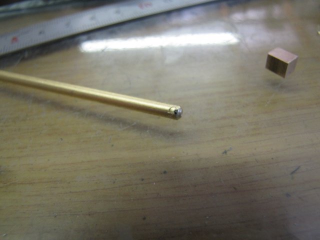
The rod and the little block will be silver soldered, and the mutilation at the end of the rod serves a dual purpose. One is to make it fit snugly into the hole in the little block to keep things aligned. The other is to allow space for flux to bubble out and silver solder to wick into to ensure a good joint.
Off to the silver soldering next; I dropped some flux and a small bit of silver solder into the hole in the block - you'll notice I didn't bother to clean up the permanent marker - that adds some contamination that will help prevent solder from going over those bits. I also fluxed the tip of the rod a bit. Poor photo; I don't know where the heck the focus was:
All clamped up and ready for the torch. A bit of weight at the top will show when the solder trapped between the pieces melts - and also prevent things coming apart as the flux starts to bubble before that, and gentle pressure on top of it once the solder melted will make sure both bits go together well:
Soldered up, and after a quick pickle:
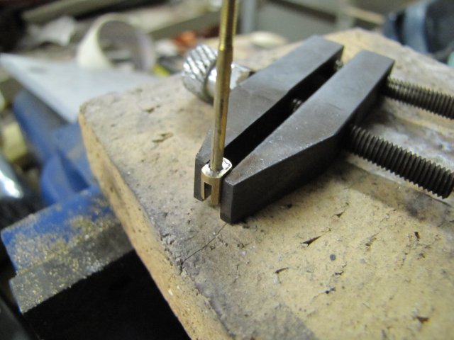
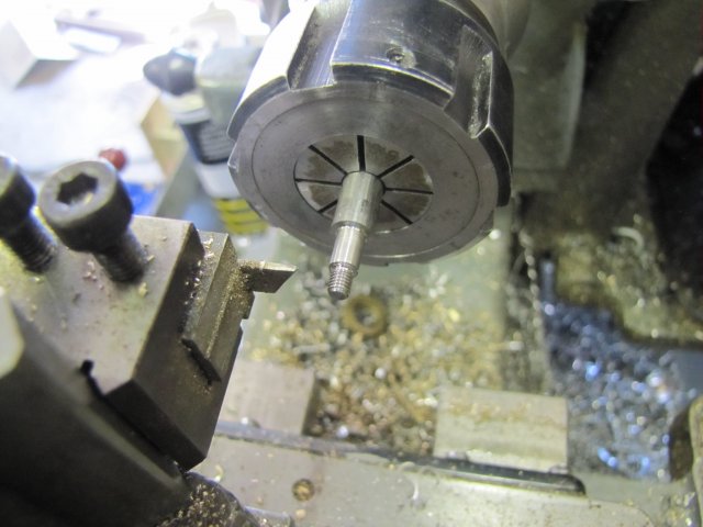
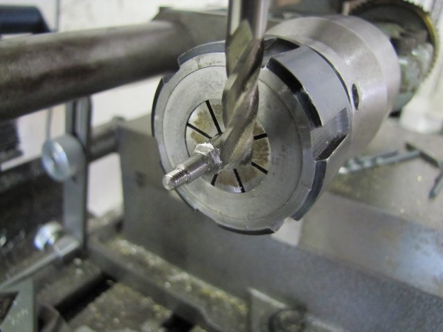
Finally, drilling the cross-hole for the linkage. I do it this way around, so that even if the little brass block at the end of the rod was a little mis-aligned, things could be recovered by filing or machining the block a bit:
I did some finishing work on the connector after that - very carefully - and as a last step the rod needed to get machined to length and threaded. Easily done by inserting it in reverse in the small ER11 collet chuck:
That end was turned down to 3mm:
After threading, adding a run-out groove, and some blinging the piston rod was done:
On to the piston. When I started off building these little engines, I thought making cylinders and pistons was the hardest part. Not so; it can be a bit of work making the cylinder, but making a well-fitting piston can be a really quick and easy job if the machining is done in the correct order on it IMHO.
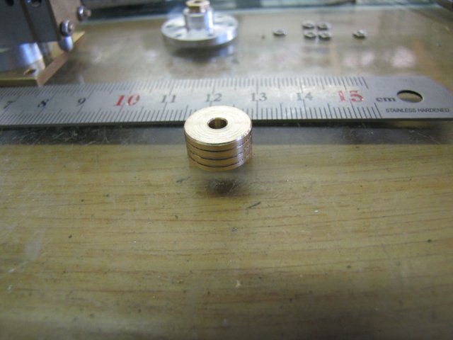
What I've found to work quite well for me, is to bring the piston close to final size, start the parting groove, chamfer both the edges with a small fine file at about 45o, and add the oil grooves deep enough that they would still be there after finishing the piston to size:
After a finish pass to get the piston to size (11.99mm in my case for the 12mm reamed bore in the cylinder - slightly on the tight side but it will run in quickly), I drilled it through 2.5mm, then 3.2mm for 3mm deep. Next I tapped it M3 to match the threads on the rod. As I'm deviating from Elmer's plan a bit here with the thicker piston rod, my thinking is along the lines that by drilling the 3.2mm bit to match my rod thickness before tapping through, a kind of a register is formed for the rod to keep it concentric, whereas if I tapped M3 first, the threads would deflect the 3.2mm drill when it started, thus preventing concentricity. Just my thoughts; you might have our own:
After parting off and removing the parting burr, the piston was done:
Took me a LOT longer to type this up than actually making it :big:
After making the piston, I set about correcting the issues so far. The valve rod's 1.5m holes were drilled out to 2mm to match the eccentric rod, and the valve rod was also shortened by 1.5mm to compensate for my earlier calculation error.
I also mounted things together, and noticed a bit of friction in the connecting rod assembly - not related to not having the parallel motion links made up yet. I chased that down to the combination of the protruding bearing bush in the column and the back of the crank disk forcing the connecting rod over at a slight angle. That was cured by skimming of 0.5mm from the back of the crank disk.
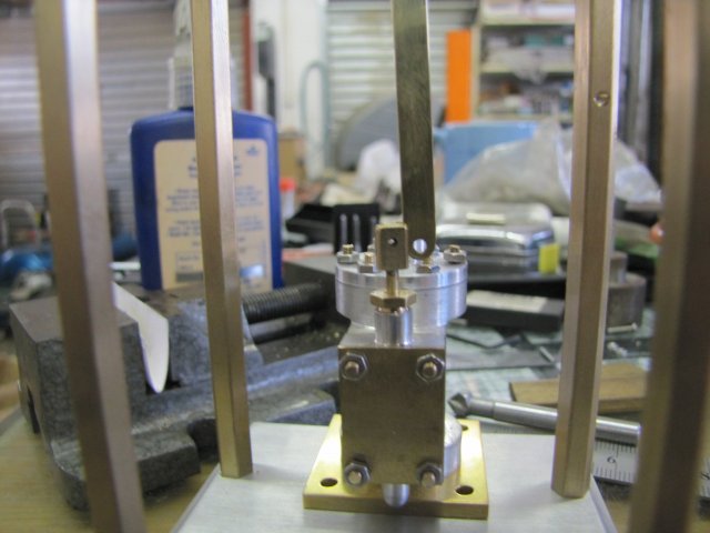
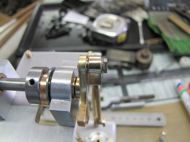
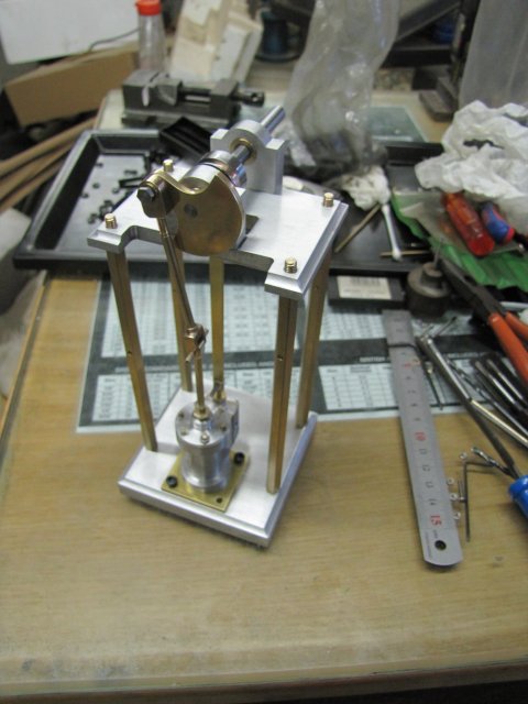
Assembled as it is in the next photo, there's very little friction left - most of it associated with the crank rod not getting guided with the parallel motion links, and the slip eccentric looks to be working smoothly as well. A Cobbled-together assembly shot:
Not much progress visible for quite a bit of work...
Regards, Arnold
- sound's like I've set up some expectations to meet for myself then :big: Thanks Jan. Yes, there are always many ways to do things - I tend to go for methods that are fairly straight forward to set up and does not waste too much raw material... The calculation errors will always be there; it's part of the fun ;DYesterday was a dead loss as far as the build goes; I paid some attention to domestic issues like fixing leaking toilets and taps, washing and polishing the car and some pleasant social interactions.
I love polished up brass cannon casings - don't ask me why; I just do. This is my tiny collection:
A couple of months ago, my one friend's father-in-law noticed these while on a visit, and yesterday evening as part of the aforementioned social interactions, that friend invited me over for a braai (BBQ/barbecue/barbie for folks in the rest of the world depending on where you are). Well his father-in-law was also invited, and upon arriving insisted that I open the Golf's boot - and then promptly plonked this one in there:
;D That's going to take a wee bit of work and a bit more to polish up! I haven't measured it yet, but it's about 1m long and looks to be about 140mm caliber, and has been safely discharged.
This morning I was awake nice and early - all bright-eyed and bushy tailed and looking forward to about eight hours of shop... Alas, that wasn't to be; we had a long power outage, so only a couple of hours in the shop.
First off, the crank screw. Some 6mm stainless steel rod turned down as needed, and threaded and a tread run-out groove added:
On to the mill, and with the dividing head mounted in the vise, a hex head milled on it. I took a cue from Dr Jo's description on milling hex bits on bolts here to minimise the burr on the threaded side, and climb milled the hex. My mill's rigid enough for this kind of operation, and it worked a treat:
After parting off the screw (or perhaps more accurately bolt, since it won't be slotted) I faced the parted end off to tidy it up a bit:
All done, though the hex head needs some finishing still:
Next, some thin washers from brass - these are not on the plans, but I want to add them to minimise friction on the crank screw The first washer was too thick:
Getting rid of the burrs on the washers after parting off can be a bit of a pain-in-the-finger - I rubbed them down on some 320 emery:
The assembled crank screw and connecting rod with the washers:
On to the piston rod. Some 4.7mm brass bar drilled 3.2mm to a depth of 3mm to accept some 3.2mm brazing rod, and slit at the needed length - in this case the workpiece length lying along the mill's Z axis:
With the bit of stock set vertical in the vise, once again slit to just before final break-through:
A suitable bit of brazing rod - with the point filed down to approximate the drill bit cone, and nipped all around with a pair of electronics side-cutters to raise some burrs and make some grooves:
The rod and the little block will be silver soldered, and the mutilation at the end of the rod serves a dual purpose. One is to make it fit snugly into the hole in the little block to keep things aligned. The other is to allow space for flux to bubble out and silver solder to wick into to ensure a good joint.
Off to the silver soldering next; I dropped some flux and a small bit of silver solder into the hole in the block - you'll notice I didn't bother to clean up the permanent marker - that adds some contamination that will help prevent solder from going over those bits. I also fluxed the tip of the rod a bit. Poor photo; I don't know where the heck the focus was:
All clamped up and ready for the torch. A bit of weight at the top will show when the solder trapped between the pieces melts - and also prevent things coming apart as the flux starts to bubble before that, and gentle pressure on top of it once the solder melted will make sure both bits go together well:
Soldered up, and after a quick pickle:
Finally, drilling the cross-hole for the linkage. I do it this way around, so that even if the little brass block at the end of the rod was a little mis-aligned, things could be recovered by filing or machining the block a bit:
I did some finishing work on the connector after that - very carefully - and as a last step the rod needed to get machined to length and threaded. Easily done by inserting it in reverse in the small ER11 collet chuck:
That end was turned down to 3mm:
After threading, adding a run-out groove, and some blinging the piston rod was done:
On to the piston. When I started off building these little engines, I thought making cylinders and pistons was the hardest part. Not so; it can be a bit of work making the cylinder, but making a well-fitting piston can be a really quick and easy job if the machining is done in the correct order on it IMHO.
What I've found to work quite well for me, is to bring the piston close to final size, start the parting groove, chamfer both the edges with a small fine file at about 45o, and add the oil grooves deep enough that they would still be there after finishing the piston to size:
After a finish pass to get the piston to size (11.99mm in my case for the 12mm reamed bore in the cylinder - slightly on the tight side but it will run in quickly), I drilled it through 2.5mm, then 3.2mm for 3mm deep. Next I tapped it M3 to match the threads on the rod. As I'm deviating from Elmer's plan a bit here with the thicker piston rod, my thinking is along the lines that by drilling the 3.2mm bit to match my rod thickness before tapping through, a kind of a register is formed for the rod to keep it concentric, whereas if I tapped M3 first, the threads would deflect the 3.2mm drill when it started, thus preventing concentricity. Just my thoughts; you might have our own:
After parting off and removing the parting burr, the piston was done:
Took me a LOT longer to type this up than actually making it :big:
After making the piston, I set about correcting the issues so far. The valve rod's 1.5m holes were drilled out to 2mm to match the eccentric rod, and the valve rod was also shortened by 1.5mm to compensate for my earlier calculation error.
I also mounted things together, and noticed a bit of friction in the connecting rod assembly - not related to not having the parallel motion links made up yet. I chased that down to the combination of the protruding bearing bush in the column and the back of the crank disk forcing the connecting rod over at a slight angle. That was cured by skimming of 0.5mm from the back of the crank disk.
Assembled as it is in the next photo, there's very little friction left - most of it associated with the crank rod not getting guided with the parallel motion links, and the slip eccentric looks to be working smoothly as well. A Cobbled-together assembly shot:
Not much progress visible for quite a bit of work...
Regards, Arnold
- Joined
- Mar 13, 2012
- Messages
- 583
- Reaction score
- 62
Looking good Arnold
One trick I figured out a couple of months ago to keep me from saning off my finger prints was to use a piece of leather between my finger that the part I am sanding. your mileage may vary, but it worked well for me when i made a similar set of washers.
I like the shell casings. I have a few 40mm casings that my dad fired from the deck gun of the USS Sealion. I have always intended to turn up some dummy projectiles for those and polish them up real nice. One of these days...
Sshire
Well-Known Member
- Joined
- Jun 29, 2011
- Messages
- 936
- Reaction score
- 259
Looking great!
I seem to remember a one of your previous tips for making washers without burrs. Correct me if it wasn't you.
Something like round rod. Parting tool in to just a bit bigger than the ID of the washer. Repeat for the number of washers needed. Then drill out the ID. Washers all done, no burrs. I remover thinking how brilliant it was at the time.
Best
Stan
Sshire
Well-Known Member
- Joined
- Jun 29, 2011
- Messages
- 936
- Reaction score
- 259
Astounding! My brain is still working.
Burrless washers here
http://www.homemodelenginemachinist.com/index.php?topic=16870.msg183877#msg183877
Burrless washers here
http://www.homemodelenginemachinist.com/index.php?topic=16870.msg183877#msg183877
Similar threads
- Replies
- 1
- Views
- 586