Edwards Radial 5 Build

Home Model Engine Machinist Forum

Help Support Home Model Engine Machinist Forum:

This site may earn a commission from merchant affiliate links, including eBay, Amazon, and others.
... today I turned up a rocker button from silver steel (drill rod), hardened it and put the ball grinder to the test.

Hi! Nice work! I'm glad to see your real life parts because I've always wondered about these particular ones justlooking at the PDF plans.

- the rocker has a short & long side. Looks like the rocker button insert goes to the long arm side & valve adjusting insert to the short side, correct?

- is the short (only) side tapped 4-40 because thats where the gap adjustment is made? (ie. and the button is fixed)

- on long side of rocker, hole dia = 0.089" vs.> button OD of 0.093. So how are these parts mated?

- dumb question, but why does the rocker button need to be a ball end vs. just rounded off? I assume its rocking in the same angle plane as the valve? So if itwas just rounded off (vs. spherical) wouldnt a line contact against the valve be better than point contact for wear etc? Maybe its threaded in too, but I dont see that detail.

Thanks, your progress is awesome!

G'day there in Calgary and thank you for your interest in my project. I will try to give a coherent answer in order of your questions.

The answer to your first question is simple - yes you are correct!

Question two is also easy as you are correct again. If you look at my photo on the previous page of rockers mounted on a head you will notice no adjuster is fitted. I have the adjusting screws ready and are using Allen cap screws rather than the slot screw shown in the plans as I think they look neater and are less prone to wear (i.e a socket compared to a slot) but am waiting for some .080" spherical diamond burs to arrive to grind the bottom of the socket the pushrod locates in.

Question three is not dumb but very relevant. The photo of the rocker button you are referring to was my first test of the ball grinder and while it ground one button OK if quite rounded it was not really satisfactory when I started a production line because of rapid wear on the grind stone. (see explanations in previous posts). In the end I just finished up making them by hand filing and hardening and polishing and you will notice that the curvature is less severe than in the first example. The actual movement or "sliding" of the button across the top of the valve stem is tiny and I doubt the curvature is critical as long as it is enough to stop the effect of raising onto an "edge". As to the fit of the buttons into the rockers they are an interference force fit. I must admit I thought the .004" difference a bit severe but I tried a test button into a scrap bit of 7075 and it pressed in nicely so that is how I did them all with no problems. Obviously Mr Edwards knew what he was doing.

Thank you for your comments and it's nice to hear from a fellow colonial.

Cheers Brian Thm:
 
Thanks for the reply. Re the profile, maybe this sketch will clarify. You made your part with a ball type end. I was wondering if the radius could be profiled, but cut in a 2D plane. The ball would make a point contact on the valve stem as it slides. The 2D profile would make a line contact.

Of course, the 2D radius button only works right if its plane was set absolutley in line with the rocker pivot plane. And thats what got me wondering about how it was retained in the rocker which you answered. But now that I look at the drawing more close, I think the little line accross can only mean 'ball'.

'colonial', thats funny. Yah, I've been called worse, Eh? :D

2013-08-04_201747.jpg


2013-08-04_154157.jpg


2013-08-04_203506.jpg
 
Hi all,
I would not have known this 45deg. cutter existed if I had not stumbled across a post by RWO. I managed to source one from a gun smith tool supplier here in Australia and it arrived yesterday after a two week wait (my reason for not doing much recently). Today I made a pilot guide 1/8" for the valve guides and 3/16" fit into the cutter and a knurled knob (the cutter has a 1/4 X 20 thread on the end to attach a knob or handle) to turn it with and anxiously fitted it to my spare "sacrificial head" and cut a trial valve seat.
To my great relief it worked beautifully and cut a very nice seat with not a trace of "chatter" and requiring little pressure and effort to cut.Tomorrow I will cut the seats in my five heads.
The actual diameter of this cutter is 1/2" and I had to grind down the nose diameter to a little over .400" using my tool post grinder on the lathe so that it would fit into the valve seat recess.
Personally I think this tool is a godsend for model engineers wanting to cut valve seats from around 1/4" to 1/2" providing they can grind the nose if necessary for their application.

Thanks RWO :bow::bow::bow::bow::bow::bow::bow::bow::bow::bow:

Cheers all Thm:

valve seat cutter.jpg


head and valve cutter.jpg
 
Brian in Oz--Regarding the 45* valve seat cutter you show in the previous post---which you found in a post by RWO--was that a purchased piece of tooling or a home made piece. Could you please tell me a bit more about it.---Brian Rupnow
 
Brian in Oz--Regarding the 45* valve seat cutter you show in the previous post---which you found in a post by RWO--was that a purchased piece of tooling or a home made piece. Could you please tell me a bit more about it.---Brian Rupnow

Hi Brian - Yes it is a purchased cutter. It is 2" long, 1/2" in diameter with a 3/16" pilot hole in the cutter end and a 1/4" X 20 thread on the other end to attach a handle. It is available from gunsmith tool suppliers and is actually designed to cut a 45deg. recess in the muzzle of rifles to protect the muzzle from damage if the end of the barrel is knocked. I purchased mine here http://www.shooters.com.au/ and the cost was A$44.05 plus postage. The brand is PTG and the part # 519840. It is very nicely made and nice and sharp and as it is designed to cut barrel steel it should have a long life when used in model engineering to cut valve seats. To suit my need I had to grind the cutter end to a smaller diameter as can be seen in the photo.
I hope this info. is helpful - if you need to know more please ask.

Cheers Brian to Brian *discussion*
 
Thanks Brian--That's good information to have. I have a couple which I built myself, based on a design by George Britnel, and they work amazingly well. I wasn't aware that they were an item which could be purchased. What I have found, after building half a dozen small i.c. engines now, is that it is better to NOT cut the seats at 45* in the lathe. I have much better results if I drill and ream the valve stem guide holes in the engine head, and then cut the seats by hand, using the valve seat cutting tool with a guide that is a "good sliding fit" in the valve guide hole. I keep my seats to .010" to .015" wide x 45*, and cut the valve faces at a 92* included angle, then lap them into the seats with #400 grit, then #600 grit lapping paste.---Brian Rupnow
 
Last edited:
It is very nicely made and nice and sharp and as it is designed to cut barrel steel it should have a long life when used in model engineering to cut valve seats.

Nice tool.

- are your valve seats the stock aluminum head, or did you modify with some sort of inserted hard seat?

- did you initially leave the valve hole unfinished (meaning no attempt at 45 deg pre-chamfer, just the passage hole edge) so the entire seating action/ depth is done with the tool? Or is this more to dress an existing chamfer to the tool 45 deg angle?

Hi Petertha - valve seats are cut directly into 7075 aluminum head as per Forest Edwards plans.
Prior to cutting the valve seats I cut a recess deep enough to square up the seating area otherwise due to the curvature of the conical combustion chamber the valve seats would not have a consistent width around their perimeter. If you go to the previous page you will see how I did this and the tool I made to do it with. I have now cut all the valve seats and included a photo to try to show the result.

Cheers Brian;D

valve seats.jpg
 
G'day all - it suddenly dawned on me that I was actually starting to put some bits together. I wanted to check that the gear assembly from crankshaft to idler gear and cam gear was all in alignment and with no binding but did not want to press fit the front bearing in until final assembly so made a temporary brass bearing for this purpose. Everything rotates beautifully - would not know any gears were involved so I am very pleased with that. I still have to organise the valve springs - I am going to have a go at making them - if that doesn't work I have found a spring manufacturer who will make them and then after assembling the engine proper will have a go at the the inlet and exhaust tubes.
I can see hours and hours of work there.
This will be my last post for a few weeks as I am taking a bit of break before getting into those springs and tubes.

How is your project coming along Michael?

Cheers all.*beer*

tempassembly.jpg
 
Aloha y'all --

Brian, that motor of yours gets more beautiful with each posting, a work of art from rocker to shining rocker. If ever a group of exceptionally talented engineers decided to get together and start their own country, that last picture could be their flag.

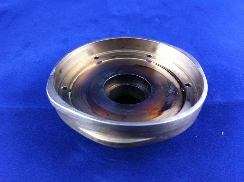
My motor, on the other hand, has been a little more arrested in its development. You may recall my last posting included a picture of a cam ring, all gleaming and glistening and perfect. Oh, how proud I was! All I had left to do was to shrink-fit the oil-pump cam and Bob would be your uncle. Well, fact is, I'd never shrunk-fit anything before, and it turned out not to be nearly as easy as I thought. In fact, I screwed it up royally. I heated the cam, slipped it onto the cam-ring boss, and...it stuck halfway down. No problem, I thought...I'll just add a little heat...a little pressure...then a little more heat, a little more pressure...all blissfully ignorant of the simple fact that now the boss is expanding just as much as the oil cam, receiving equal treatment from the blowtorch and is of course jammed on tight and jamming on more tightly evry second. Finally, in all the excitement of the moment, sufficient heat and pressure has been applied that, although the oil pump cam hasn't moved a micron, this burnt and bent piece of wreckage is the result:


Sad, but educational in several ways.

First, some fundamental laws of physics are indelibly impressed on memory, and future shrink-fitting tasks are given a much greater chance of success.

Second, the difference between frustration (like when you scratch a surface, or turn a few too-many thou off a billet) and !!!RAGE!!! (like when you do something as dumb as this to an otherwise-perfect part) becomes really apparent.

Frustration makes you say a few naughty words, sometimes quite loudly. :rant:

!!!RAGE!!!, by contrast, makes you go all quiet...you just stand there, staring at the carnage disbelievingly, amazed that that you ever had the audacity to even touch a machine tool in the first place. :eek: If there's music playing somewhere you turn it off, so you can be alone with your trembling thoughts. You know that any move you make has to be very carefully considered, especially in a room with so many sharp and pointy edges. Finally you very carefully pick up your keys, turn out the lights, and leave. You drive home very slowly.

Then, if you've made it this far, you sit down in front of the computer and order up some more material so that, a few weeks later, you have not one but two cam rings...one Hyde, one Jekyll:


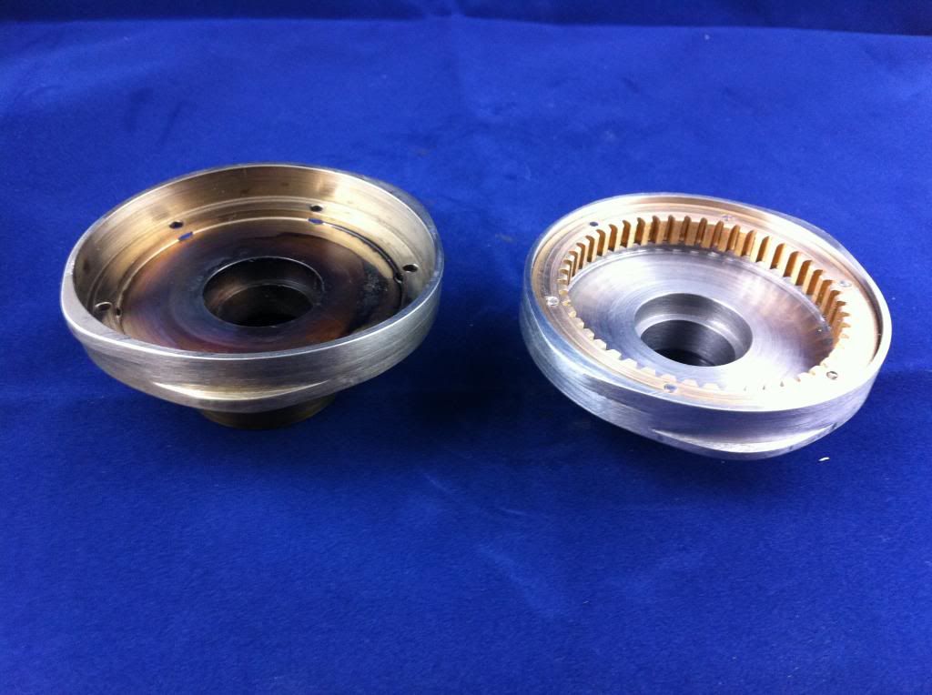
You find that you've learned how to properly shrink-fit the oil-pump cam:


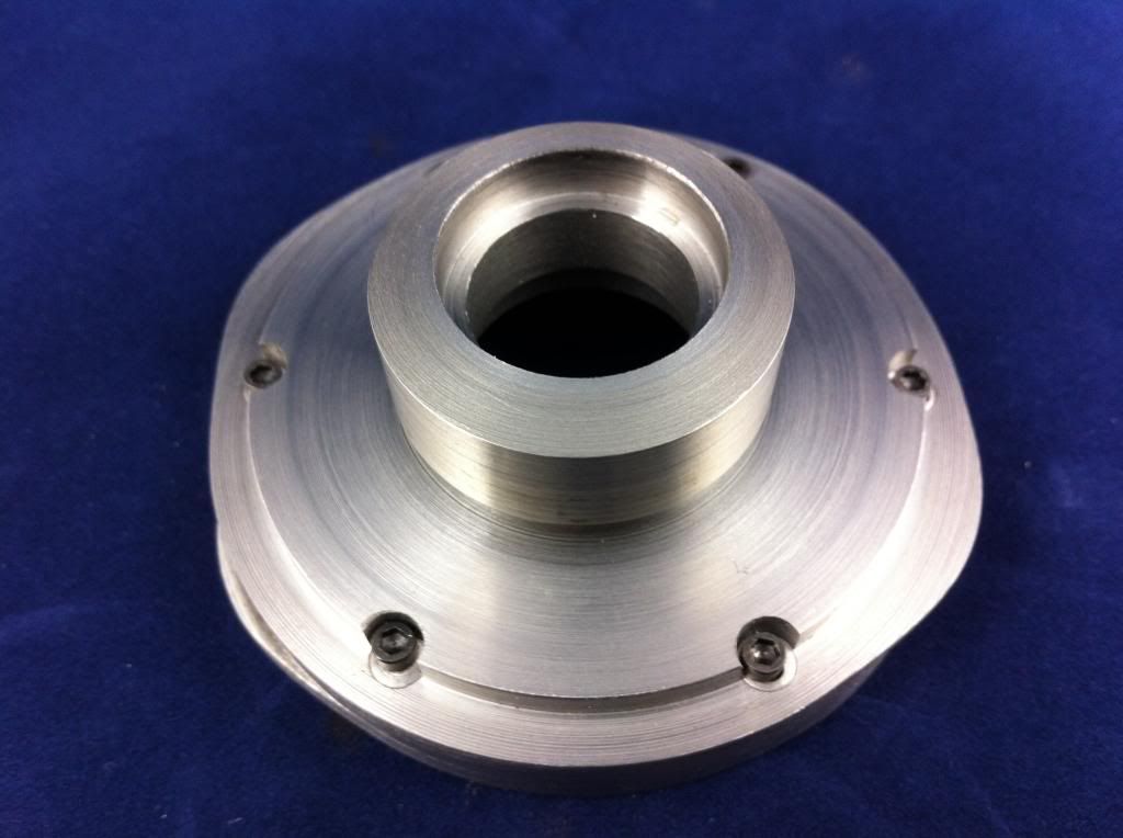
Then you think back to the last time this happened...remember the Great Crankshaft Screwup, when a tap got snapped in an almost-completed crankshaft, reducing it immediately to paperweight status? Well, I got as far as ordering new material, but didn't take it any further...in fact, the Cam Ring was taken on for the sake of corrective therapy as much as anything else. Well, the final lesson of the Parable of the Second Cam Ring proved strong enough for a new chunk of 4350 to be hacked away at, this time with much better results:


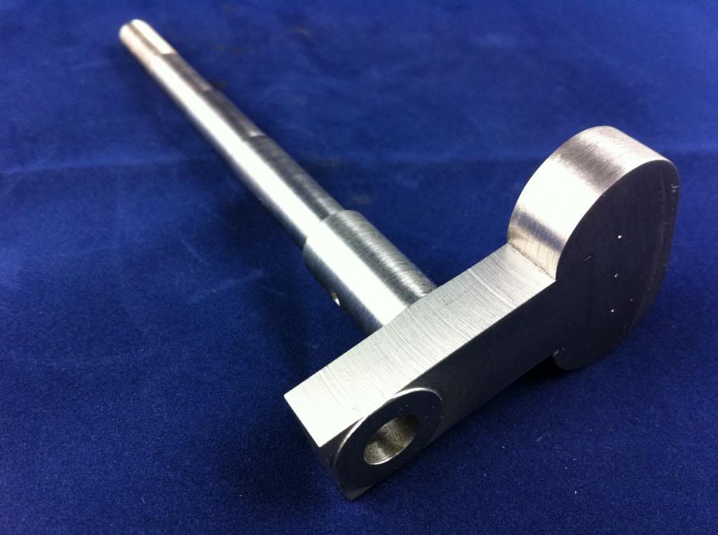
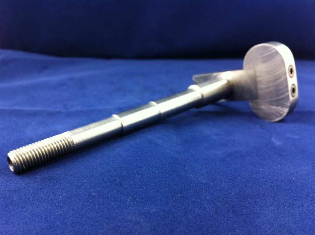
It turns out the new crankshaft even fits where it's supposed to, and has made clear that the next few projects all have to do with finishing out the "bottom end" of this motor:


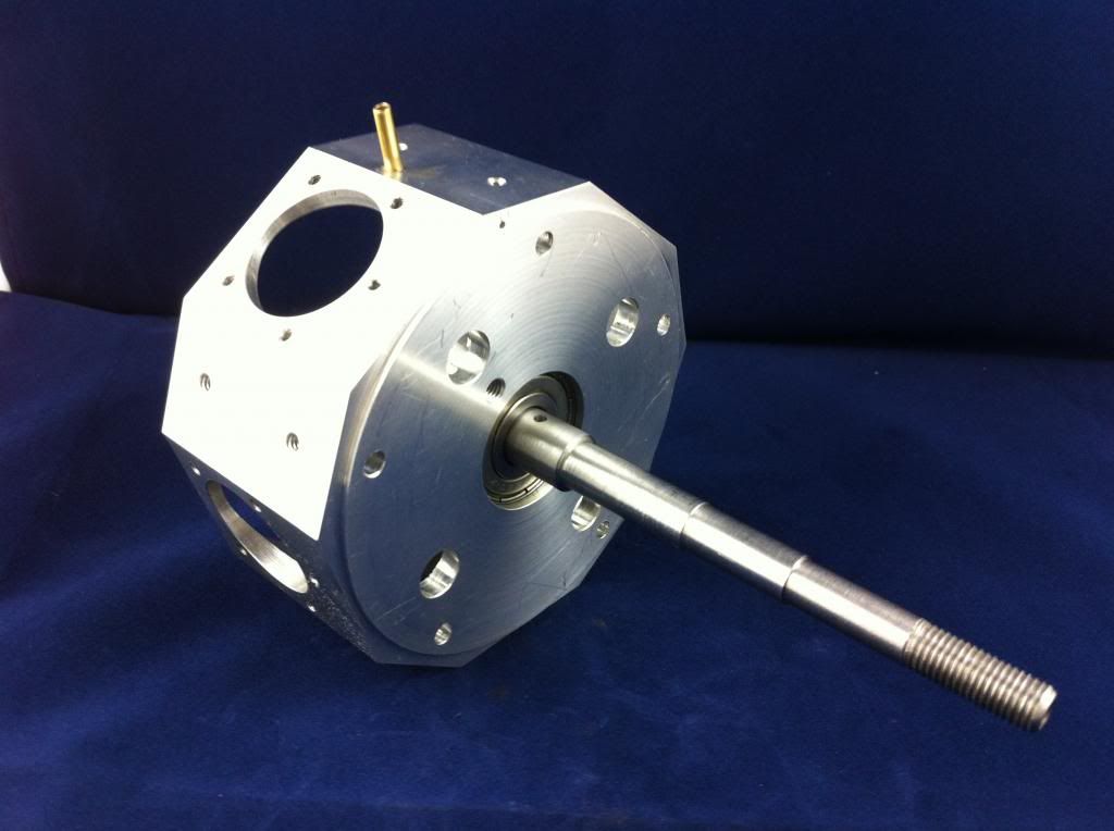
So after getting all the spacers and gears running right, it'll be all about making the cylinder liners and piston rings (and, never having machined cast iron before, I'm assured of lots more fun and games) and getting pistons and rods and bearings all working and dancing in harmony. After which I can FINALLY get around to the business of the heads and valve train.

Something else I've learned, by the way, is the importance of having another project going along at the same time, something to turn to at times of great exasperation, or simply while waiting for materials to arrive; I've started slowly building a micro drill press, which I've begun to realize is a very desirable thing to have around for the drilling of anything less than 1/16". This one's based on a design by Jerry Howell. Not in a real hurry for it, but it's a fun project to turn to when confronted by what seems for the moment to be a brick wall with the Radial 5. (And they're never really brick walls of course, just thickets to be scambled through).

But eventually, down this road somewhere, I'm still convinced, there's a 5-cylinder radial, and it'll be a runner, and a source of great pride and joy.

Thanks, Brian, for your continued inspiration.

Michael T
 
Last edited:
Hello Michael and all of you folks. Unfortunately I cannot find any plans, or useful infos on the web, concerning ignition(s) and carb for the Edwards Radial 5. Suggestions? Regards - Moshe
 
Hi Moshe,

As far as I know Forest Edwards only made his plans for a glo ignition engine available to the public forum although he made spark ignition versions. Hall effect ignition kits are available from the likes of Hemingway Kits in the UK.
I purchased my carby from Gary Conley at Conley Precision Engineering. I described the engine I was building and he made a recommendation. Unfortunately I am currently on vacation in Queensland and don't have it in front of me to give you the model number. Gary Conley owns Perry Carburettors and he is a most helpful guy. If you like I can post the model number when I return home in 2 weeks. Are you building or plan to build an engine ?

Cheers Brian. Thm:
 
Michael - I can't believe how you felt when that cam ring jammed (well actually I can as we've all "been there - done that".) You are an inspiration to all model engineers in the way you treat it as a learning experience and just get on with it and make a new piece. You also have a wonderfully poetic way with words that make your descriptions so entertaining. I am afraid mine seem to come out a bit clinical by contrast - guess that why I failed English class - all I was interested in was hands on craft classes. That new cam compete with oil pump cam attached looks just great. I am currently doing this post on my wife's iPad as we are on vacation visiting family in Queensland - about two thousand miles closer to you than normal so this post should get to you a bit quicker.
You mentioned getting into the cast iron cylinder liners soon - I wouldn't worry to much about this as In my opinion cast iron is quite nice to machine apart from the fact it can generate a bit of a mess. Machine it dry as the graphite in it provides lubrication. A while ago I machined up a chuck back plate and couldn't believe the amount of black dust that had settled on everything in the shop.
I recently purchased a three ton arbor press for the press fits required on the Edwards and it was just perfect for fitting the liners to the barrels. The fit tolerances provided in the plans seem just right as the amount of force required to get the cylinders into the barrels felt just right. When I get back home I'll have a go at making some valve springs.

Keep up the good work - Cheers Brian :toilet: then Thm:
 
Last edited:
Thanks, Brian, for your kind words about my words. Words, actually, are how I make my living, but machining these engines is how I know I'm here from day to day. Once you've made a part, right or wrong, it's going to be just as right or wrong the next day. Words are more flexible, and not so trustworthy. A piece of metal can't be argued back into a different shape after the deed is done. It's not forgiving, and so totally rewarding.

Sorry to get all metaphysical, but it's why I love this hobby.

I'm getting set to make those cylinder liners, but might make a little more progress on that little drill press first.

Enjoy Queensland. I hope to see it one day.

Best,

m
 
I am amazed at how this thread that I started all that time ago has progressed. Following Michael and Brian's progress has been a great way to spend a couple of hours, and has prompted me to try and get out to the shop and make some more progress... You have both made a great job of your respective builds. Thm:

Since my last post, I have had some other long term projects that have been taking up my time - and she is three years old now, and very curious about all of the strange machines in 'Daddy's garage'. ;)

I have managed to complete some more of the radial since the last photos were posted. The crankshaft and cam drive gearing are now complete, plus odds and ends like collets and valve keepers. Still a lot of the small parts left to complete, which makes the '% complete' figure on my build spreadsheet remain annoyingly on the wrong side of 50% I must get my finger out and get the engine finished. I started it in March 2004. Is nearly 10 years the longest anyone has taken to build an Edward's Radial, I wonder? :eek:
 
Last edited:
G'day Anthony and a big welcome back to your forum.

It was your original postings that inspired me to have a go at building an Edwards Radial in the first place. I often wondered if you had completed your engine and had it running but now know you had the best reason of all to put it on hold for a while. I could not have contemplated a project like this when my kids were little.
I am sure everyone visiting the forum looks forward to hearing more about your build as you get back into it. I know Michael and myself certainly will.

Cheers for now. wEc1 BACK
 
Thanks, Anthony, for letting us use your thread for so long! I'm sooo glad you're back...all this time I've had the vague feeling of camping out in someone else's living room.

Along with Brian I have you to thank for getting me started on the Radial Trail. Well, mostly anyway. Truth is I originally built my little shop a couple of years ago to help me with a robotics project I had going on, and then happened to build a couple of small motors (one steam, one Stirling) as a way of developing my machining chops, and then just happened to spend a couple of stray hours last December in the Air & Space Museum in D.C. While my wife was off inspecting the uniforms of the dashing airmen of WW's I & II, I found myself pulled toward the engines of the twenties thru the forties, especially the radials. A week later, at a dinner party, a chance conversation with a garage-owning friend led me to believe that I hadn't built a REAL engine until I'd built an I.C. engine. Later that night I googled "model radial engines", and at about four a.m. found your thread. I think you had me with that first picture, the one of the pile of raw stock, waiting to become an engine. If not there, then your description of how you machined your heads.

Anyway I've barely had a discretionary moment since that hasn't been radially-oriented, for which I thank you. (My wife, not so much).

Looking forward to new pictures.

Warmest aloha,

m
 
Greetings Comrades --

Time to send up a flare lest anyone think I'd moved on to macramé.

Slow but definite progress on the old Radial. Like you, Brian, I was well pleased with the way the whole gear train works -- just enough backlash to let my fingers know that things aren't packed in too tightly, and a softly satisfying whirr from inside the cam cover when a prop is mounted and spun. Of course, there aren't any finicky pistons or link rods to get in the way yet. Here are pics of the bottom end assembly from front and from back, sans prop, sans rear cover, sans cylinders, sans everything.


Day job's been hell lately, and such shop time as there's been has gone mainly into the micro-drill-press project (maybe I'll start another thread for that one) but the cast iron for the cylinder liners and rings has just arrived and so it might be time to start making a mess. Certainly, it's an excuse to put off laundering my shop coat, there's just no point with all that cast iron dust in its future.

Aloha,

m
 
Last edited:
Cylinder liners are done and luvly. The rings are more of a challenge, but once I get the hang of parting them off at the right thickness -- the first few have been four or five thou too fat -- I'll be sure to make at least a double quantity for spares...they just seem so fragile.

Meanwhile, Brian, I confess to covetous thoughts concerning your surface grinder. It just seems it would be so much easier to make 'em fat and then slap 'em onto that magnetic chuck for a quick shave to size...

m
 

Latest posts

Back
Top