Gd,evening Michael - great to see you back on the job. First light up time (hopefully) is still a bit into the future even though there is light at the end of the tunnel I am a slow worker. I would appreciate your opinion on a few issues remaining in the build and how you intend to tackle them but first the bender. In the Hemingway kit plans there are measurements for several formers but none are for a 1/2" radius one to suit the required OD of the tube. I have only made one former of 1/2" radius to do the job and will make them if and when required for any future projects.
1. Valve springs and oil pump plunger spring. I notice you have a spring on you oil pump plunger. Have you managed to source off the shelf springs - had them specially made or wound them yourself? I have not been able to find any off the shelf springs the right specs. in Australia although there is a company in Perth that will apparently make them. I do actually have an unmade spring winder kit (also Hemingway - I think we are keeping them solvent) but am unsure what path to take. What do you reckon?
2. Gaskets - the plans show no gaskets under the barrels or heads and these will be essential. I have ordered some 1/64" gasket material from Omni Models which I hope will be OK but this will have some effect on compression ratio. the plans call for machining an amount off the top of the cylinders to adjust compression ratio on all cylinders to 8.5 to 1. I believe this is necessary anyhow to compensate for the fact that the master rod and link rods in the Edwards Radial are equally spaced where as ideally some compensation needs to be made for the fact that the non articulated master rod has a slightly different TDC than the link rods. ( the math is way beyond me).
What did you plan on re gaskets?
3. Have you had any thoughts on a glo driver - it is likely it may need one especially at low RPM - and lets face it - that's where these things really get the pulse racing?
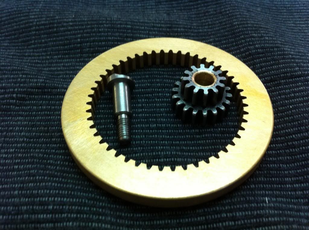
Well that's probably enough to churn around for now - the only thing I have done since the bender is make the idler shaft and bore and recess the pinion gear. Looking forward to photo's of the pistons taken in the new light box.
Cheers for now - Brian scratch.gif
Yo Brian --
Light box hasn't arrived yet but...Hallelujah!!...I've finally managed to bring five serviceable pistons into the world. Actually, six, since I've finally learned to make some spares when making multiples, just in case. Such a silly thing to do the same setups over and over again, even if practice does make perfect. Here they are, photographed the old-fashioned way...
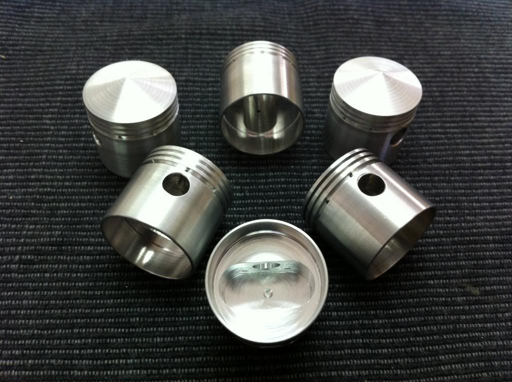
....and, here's the sad little graveyard of piston-wannabes that just somehow stumbled into blind alleys along the way, never to make it out again...

This little pile will certainly come in useful if I ever do a casting project. Meanwhile it just serves to keep me humble.
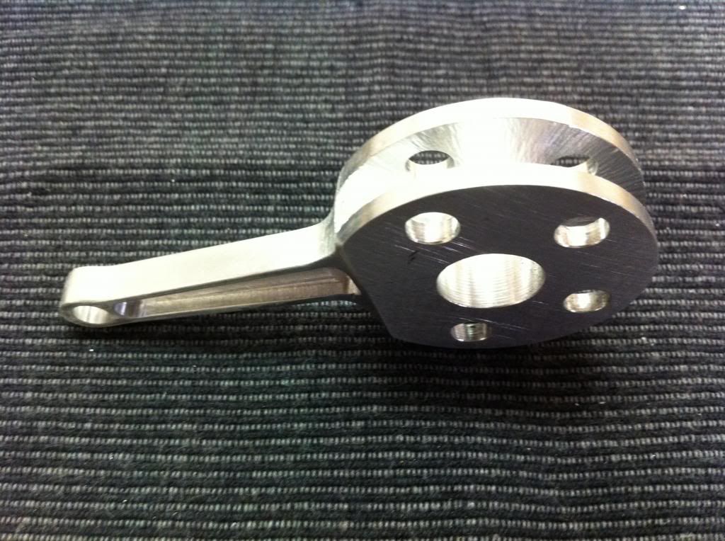
There have been other little bits and pieces that have gotten done over the last month or so...the master rod...
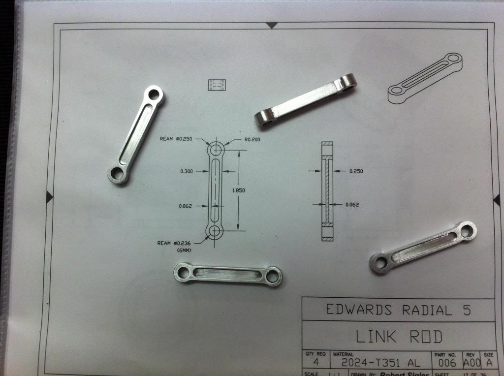
...some Link Rods to keep it company...
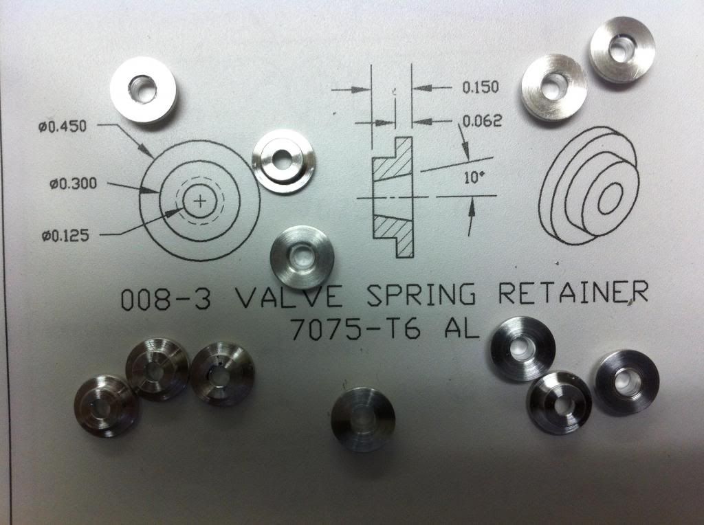
...a few Valve Spring Retainers, just on the off chance I may one day get around to machining some Cylinder Heads...
...an Idler Shaft with some relevant Gears...
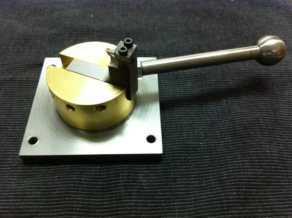
and even a Ball Cutter for eventually turning those tricky ends on the Pushrods. (It's first and only product so far has been the ball on its own handle).
It still seems like an awfully long way to go, but an inch at a time, then another inch...
Brian, the best source I know for springs (and for most hardwatre, come to think of it) is McMaster-Carr. The spring for the Oil Pump, as well as the valve springs, are stock items from them. On gaskets: Yes, I'd assumed that they would be necessary, but hadn't got around to sourcing them yet, or thinking much about how to reconcile that with the compression ratio issue. Haven't even figured how I'm going to even measure the CR...is there a gadget for that, I wonder?
You're also way ahead of me on concerns about the glo-plug at low RPM's, thpough I have been nursing an idea that I'd like to investigate a spark mechanism rather than a glo. Hemingway's Hall Effect kit seems a possible candidate. That's as far as I've got.
Got to run...SWMBO calls.


