Edwards Radial 5 Build

Home Model Engine Machinist Forum

Help Support Home Model Engine Machinist Forum:

This site may earn a commission from merchant affiliate links, including eBay, Amazon, and others.
Hi Brian,
In regard to your response in post #118 here is what I did for my master rod/slave rod placement when I was building my radial. Although I had read information on the subject many years ago in one of the issues of SIC I couldn't remember exactly what it said nor did I want to go through boxes of magazines to find it so I did my own layout.
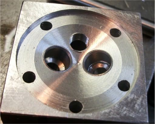
The layout plan behind my thinking was that each cylinder is equally spaced about the crankcase so they are on 72 degree spacing. The master rod was drawn with the proper length and throw sizing. In picture #1 starting from the right I have the sequence of master rod/slave rod pin positions for each TDC point of the appropriate cylinder. I figured that by rotating the crank 72 degrees (cylinder spacing) and drawing a line through the center of the cylinder until it intersected with the throw circle this should give me the correct pin spacing. Quite naturally the camring is going to be equally spaced relative to TDC so therefore each of the cylinders should be at TDC at the same time.
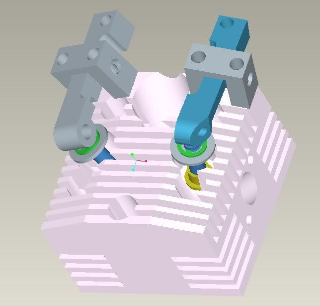
When I started designing my engine the basics for it were taken from the Morton M5 radial engine. Their pins were equally space about the master rod. Knowing that there should be some compensation I did the layout. As can be seen by the 2 bottom views there is a difference between the 2 spacings. Whether mine is totally correct or not I can't say but it should be much closer than than just equal 72 degree spacing.
gbritnell

Thanks for the info George (have I got that correct?).
They are nice drawings and when I find time I will try to get my head around the rod spacing theory. Forests' solution to adjust the compression ratio by trimming of the top of the cylinder liners must work OK in a small engine as his were work horses that were actually flown in RC planes and not just display engines. What my engine finishes up doing depends on how, when and if it runs. This is my first engine (pretty much first anything) and if nothing else it has forced me to have a much better equipped shop than when I first started. When my Dad passed on he left me his 9" Hercus (Southbend Clone) lathe that he purchased in 1949 and a nice mill which sat around unused in my garage until I retired two years ago. I couldn't bear to see them just sit there so got my act together and built a shop on the end of the garage, started the Edwards Radial and as they say "the rest is history".

Thanks for your interest - Cheers Brian Thm:
 
G'day Michael - you amaze me at the rate of knots that you can turn stuff out and really nice stuff too. I am particularly interested in that ball turner and can you give an idea of its actual size. I bought a ball turner from the Little Machine Shop some time ago and it works fine on balls around 1/4" or so and up but performed poorly on the tiny balls for the end of the pushrods. Maybe I didn't persevere long enough but it seemed that the work speed was to slow at such a small diameter even with the lathe running flat out. Anyhow I shoved them to one side waiting for someone like you with the balls to come up with a solution.

Aloha ahiahi - Brian :bow:
 
Great work Michael.

This is going to be my next project, so I am greatly interested in your trials with the pistons. Are they particularly hard to machine or was it a matter of learning the proper technique?

Ron
 
Haven't even figured how I'm going to even measure the CR...is there a gadget for that, I wonder?

Hi Michael,
Compression ratio is simply the total volume of the cylinder(+head gasket +combustion chamber etc etc) with the piston at BDC, divided by the total volume with the piston at TDC.

Not sure about non-metric countries, but here in Australia on full size engines the measurement of the volumes is known as "CCing" (seeseeing) and isn't really that difficult, tho it does get tricky when you have high dome pistons that protrude above the block deck at TDC :D (tho there are relatively simple work-arounds for this situation)

There should be plenty of guides on the process on the net, i found a basic one here: http://www.diyporting.com/cc.html

Edit: I noticed in that guide the "Dispenser Pump" without a graduated scale.... forget this.
Any decent Chemist (Drug Store) will have accurate Syringes with a scale printed on them in all sorts of sizes down to around 1cc for about 50 cents each.
These are much preferred with great accuracy:

syringe3.jpg
 
Last edited:
  • Like
Reactions: xjs
G'day Michael - you amaze me at the rate of knots that you can turn stuff out and really nice stuff too. I am particularly interested in that ball turner and can you give an idea of its actual size. I bought a ball turner from the Little Machine Shop some time ago and it works fine on balls around 1/4" or so and up but performed poorly on the tiny balls for the end of the pushrods. Maybe I didn't persevere long enough but it seemed that the work speed was to slow at such a small diameter even with the lathe running flat out. Anyhow I shoved them to one side waiting for someone like you with the balls to come up with a solution.

Aloha ahiahi - Brian :bow:
Brian -- The Ball Turner in question is based on Steve Bedair's -- he's the guy with the site dedicated to the domestication of the Chinese 9x20 lathe that so many of we lesser mortals use. It's an interesting site, even if you have a real, grownup lathe. To give an idea of scale, the HSS toolbit in the pic is 1/8" square, and the ball on the end of the handle is 1" dia. I seem to recall that the round brass piece is about 3 1/2" diamter (I'm not in the shop just now so I'm guessing). I have no idea how effectively it will produce the pushrods...I just know that's the plan. Now I'm working on the link rod retainer; once I get it done perhaps I'll give the pushrods a go, and see what happens. stickpoke
 
Great work Michael.

This is going to be my next project, so I am greatly interested in your trials with the pistons. Are they particularly hard to machine or was it a matter of learning the proper technique?

Ron

Aloha Ron, and thanks for the encouragement. Please know that the pistons are by no means the most challenging part of this project (unlike, say, the crankshaft or the cam), and that my difficulties with them have been very largely self-inflicted and/or bone-headed. Breaking 0.043" drillbits unnecessarily, drilling holes bigger than the reamer, making a milling cut exactly 90 degrees in the wrong direction, that sort of thing. Nothing a bit more focus couldn't have avoided. :mad:

I'm so glad to hear you're going to take this project on. The world will be a better place with more Edwards Radial 5's in it, not to mention more people who have built one. The process seems to require patience but is enormously satisfying...especially for those of us with so much to learn...and if it were any more fun I'm sure they'd make it illegal.

wEc1
 
Hi Michael,

Not sure about non-metric countries, but here in Australia on full size engines the measurement of the volumes is known as "CCing" (seeseeing) and isn't really that difficult, tho it does get tricky when you have high dome pistons that protrude above the block deck at TDC :D (tho there are relatively simple work-arounds for this situation)

:

Many thanks, Simon, that's a great help. Takes me back to the days when we'd do something similar to measure combustion chambers on race engines so we could make sure they were all exactly the same size, part of the whole "balancing" ritual.

As has been noted the only corrective adjustment for compression ratio with this motor is the removal of small amounts of material from the top of the cylinder liner. I'm guessing that measuring the combustion chamber as per your recipe, and then measuring the volume of the cylinder at BDC in the same way, would provide the necessary numbers for computing the CR -- after making the adjustment for the pointy top of the piston, of course. The swept volume is still only about a dozen cc's or so, so the same instruments should work?

Love your choice of quote as a signature. I guess "Cheap Chinese" has been my version of "CC-ing." It makes it all possible.

Aloha,
 
Now I'm working on the link rod retainer; once I get it done perhaps I'll give the pushrods a go, and see what happens. stickpoke

Brian -- Unable to report on efficay of ball turner for now -- I discovered that the 3/32" stock for the pushrods is too small for my lathe's 3-jaw; then I discovered that, to make the special collet I'll need to grip the stock, I'll need to do a milling setup that requres a piece of equipment I don't currently have -- a toolmaker's vise small enough to mount to an angle plate while using a slitting saw along the length of the collet to provide the necessary squeezability.

Pant, pant.

So, while waiting for the new vise to make its way out here I've started hacking away at the Cam Ring, which looks to be a challenge. So, even if they choose to deliver the vise by hot-air balloon, there's lots to keep me busy till it gets here.

Cheers! *beer*
 
Do you have a tap handle you can pur in your lathe chuck to hold the 3/32? You can buy pin vises very reasonable.
 
Michael - this is my solution to hold tiny pieces of work that a standard lathe chuck won't grip. I think most lathes have a morse taper in the spindle (mine is #3) so I just use this drill - mill chuck which grips to zero. It has a #2 morse taper so in my case I need to use a #2 to #3 adaptor. I have taken some inspiration from your ball turner and am thinking of adapting the design to hold my die grinder to grind the tiny .125" radius on the hardened rocker buttons and may also work for the balls on the end of the pushrods. My tool post grinder is to bulky to adapt to this delicate task. Making tools to do a job usually takes longer than the actual task at hand.
I will dutifully keep you informed as to any progress or otherwise.

Cheers Brian:wall:

chuck copy.jpg
 
  • Like
Reactions: xjs
Michael - this is my solution to hold tiny pieces of work that a standard lathe chuck won't grip.

Thanks, Brian. This has to be my biggest "Duh!" moment for a while, but it's worth it just to see another great pic. As I mentioned I've started carving my Cam Ring , but I'll give this a shot when I get through the turning and boring.

Also, I'll get a few pin vises on order...can't imagine how (or why) I've gotten by without any so far.

Glad my ball-turner proved muse-worthy, even if it hasn't actually produced anything yet.
 
G'd evening Michael and all - after taking inspiration from Michaels ball turner I have come up with this contraption to enable (I hope) to grind the .125" radius on the hardened steel rocker buttons. The principle is the same as for the ball turner but substitutes an air die grinder in place of a cutting tool. My die grinder has a female threaded section in the front where a cover normally fits so I was able to make a threaded holder to screw the die grinder on to. The turntable body fits in place of the compound slide on my Hercus (Southbend clone) lathe and will accomodate a ball diameter up to 2 inches however I doubt I will ever want to grind a ball this large. The knurled pin can lock the turntable square to the chuck so it can also be used for cutting off, grooving and facing etc. I only finished making it today and as yet not had a chance to try it - I intend to do that tomorrow and will report as to the success or otherwise and post a picture of the results.
This turned out to be a lot of work to make a tool to manufacture such a small part but I could think of no other way to do it.

Cheers Brian - will report back soon :shrug:

ballgrinder1.jpg


ballgrinder2.jpg


ballgrinder.jpg
 
G'day Michael and all - today I turned up a rocker button from silver steel (drill rod), hardened it and put the ball grinder to the test. It looks like it will do the job even though it doesn't "sizzle" like the tool post or flat bed grinder - a problem when working so close to center with such a small radius which reduces work and grinder effective speed. The lathe was run in opposite direction to the grinder. Having gone to all this trouble and looking at the finished item I wonder whether a bit of careful work with a fine file to produce the radius then polish, harden and polish again wouldn't produce a satisfactory item. None the less I am happy with the results and will go ahead and grind up the remaining nine and press fit them to the rockers.
The actual size of the rocker button is 1/4" long and 1/8" in dia. - see photo.

Cheers Brian :wall:

rockerbutton.jpg
 
Aloha Brian and Company --

Didn't mean almost the whole month of July to slip by without posting, but life's been getting in the way a bit. A few stolen hours here and there, though, have allowed the Quest to inch forward, and I'm pleased to report that the Cam Ring is now a quadra-lobed reality:


The prospect of making this cam ring was the whole reason for getting into this thread in the first place, and I still don't think I'd have been able to pull it off without all the help and advice. It's been a great experience, though, and I've learned a lot. 23 hours from start to finish, one little nibble at a time, but here it is. And, here it is from the other side:


The oil pump cam should be made and shrunk-fit in place in the next few days, and then I'm not sure what gets tackled next. I'm itching to get my hands on those heads, but should probably get the valve train out of the way first.

Brian, that setup you have for grinding those teeny-weeny rocker buttons is amazing, and produces a beautiful product. I've been trying to think of other small hardened thingies with hemispherical ends that need making by the dozen so you could get some more use out of it...if any occur to me, I'll pass them along. And oh yes, the tube-bending kit arrived from Hemingway a little while back. Looks like fun. Perhaps I'll take a break from The Motor to make a special tool or two.

All best,
 
Hi Michael and all,
first congratulations on the cam Michael - looks really great and it wasn't as bad actually doing it as thinking about it was it? Also looks like your light box is in action - great photo's. The funny thing about these projects is that some things that look like they are going to be difficult run smoothly while others that appear to be simple turn out to be problematic - e.g. those damn pesky little rocker buttons.
It turned out that my radius grinder didn't really work as planned once I started to grind more buttons. Problem was that working so close to the centre axis and with low actual cutting speed despite 25,000 RPM the stone wore very quickly and started producing inconsistent radii that became more cone shaped than a nice smooth curvature. So - back to the drawing board and the end result was to resort to that ancient hand held tool called a file. This turned out to be surprisingly successful with very little effort - filed hardened and polished with the finished result in the photo below. The saving grace is that the tool may be versatile enough to find some use in future projects.
I did have more immediate success though with the rocker pins and a spot cutter to recess the valve seat area prior to cutting the actual valve seats.
The hardened 1" X 1/8" dowel pins were cut to length and grooved with a 1" X .012" diamond coated disc mounted on my tool post grinder running at 20,000 RPM - cut through them like butter and the circlips fit into the .004" deep grooves a treat.
I have also made a tool to spot face the valve seat area to make it flat before cutting the valve seats. The cutter itself is actually made from grinding down a cutter from a household tap (faucet for our American friends) reseating kit. I have so far only cut a trial in my sacrificial head but it cut by hand with very little effort but this time will make no claims of success until all ten seats are cut. I still haven't decided how to actually make the valve seat cutter but will keep information flowing in this area.
Sorry! this post seems to have become a bit long winded so will terminate for now.
Cheers Michael and all - take care - Brian :toilet::shrug:Thm:

rockerandbutton.jpg


diamonddisc.jpg


headand cutter.jpg


headspotcut.jpg


valveseatspotter.jpg
 
Hi Jeff - thanks for your interest. I am fascinated as to the reason for the square adaption of the Edwards head design. Have you used the basic design on a different engine or one of your own design? I also considered inserts but in the end decided to run with aluminium valve seats as per the Edwards specs. but incorporate phosphor bronze guides.
Cheers Brian. ???
 
The valve seats were not called out real well in the original drawings, so I drew it in cad and came up with that. Used the square cylinder heads on an engine of my own design.
Square made a lot of things easier in the workholding and machining department. I believe the 6061 square stock was a little cheaper then the larger round stock as well.
head.jpg
 

Latest posts

Back
Top