Economic Motor project

Home Model Engine Machinist Forum

Help Support Home Model Engine Machinist Forum:

This site may earn a commission from merchant affiliate links, including eBay, Amazon, and others.
Thanks guys for all the nice compliments.

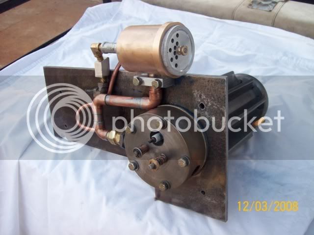
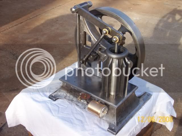
CrewCab, I used a DRO to lay out the cyl head bolt circle and also spot drilled the outer fin groove. Then I mounted it on a spacer and cut the slots. No CNC in my shop {yet}.

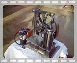
Chuck Foster, Thanks for the link. That is the engine. Economic Motor Co. acquired this patten. This sure gives me a lot more to work with. All I had was the pictures. I was just starting to build the cyl head and was just guessing at how it was built. Now I need to set back and study these plans. Tom
 
Tom your fabrication are absolutely amazing!

Please keep them coming.

Rick


Not to take anything away from Tom's thread but just a note on fabrication that might help others.

Some years ago one of my customers sold a large 1960's woodworking machine for a very good price. On loading this they dropped it and smashed the large end casting beyond repair.

Because the new owner had seen the machine and knew what to expect i was asked if it was possible to make a new cover, casting was out the question given no patterns and the size so I fabricated one.

Being 1960's it was all curved surfaces with about 2" radii on all corners so I slit a thick walled 4" pipe lengthways into 4 slices and used these on the corners. All MIG welded, ground up, thick coat primer and sent out.
They then painted this same colour as the machine and it was indistinguishable from new.
 
Beautiful work Tom and the unique design only adds to it. I too will be following the thread with great interest.

Bill
 
Hey John, That is how I started out to do it. But I couldn't figure out how to bend the split pipe into a radius for the top piece so I decided to use a piece of solid bar and mill it flat on the bottom. I tried this but it just didn't work out.
So I just used a piece of strap. Thank you for your input. Tom
 
Tom T said:
I used a DRO to lay out the cyl head bolt circle and also spot drilled the outer fin groove. Then I mounted it on a spacer and cut the slots. No CNC in my shop {yet}.

Thanks for the feed back Tom.

CC
 
Tom...

I look away for a few days... and WOW :bow: those fins are awesome!

looking good. Keep it up!

Eric
 
very nice job Tom, with the price of castings fabrication is where we'll have to look. Its great to examples of how built up and bar stock construction can producing great looking and historically accurate models. thanks for all the pics
 
Watching this one come together with a healthy dose of awe!! Love those fins.

Steve
 
Hello all, My son and I started doing a little testing on this engine this evening to see how the fuel system might work. And I'll be darned if it didn't start on the first try. Shocked us both, went and got my wife and the video camera. Took a little movie. I am just holding my portable propane torch up to the intake pipe [no fire just gas]. You can here the engine speed up and then starve for fuel and miss a few beats. I am really surprised this engine will run at all. I don't even have a piston ring on the piston yet? I will post some better pictures and video soon. When I come back down to earth!!!! :eek: :eek: :eek:

 
Tom

anim_19.gif

great going !!

from start to now how long has it been??

a few weeks??

sheeesh..

sounds great

jack
 
Very impressive. Very interesting to watch it run. How does that exhaust work?

Chuck
 
Tom,

That is just unbelievable
wow.gif
wow.gif


Sorry but I don't have any words other than GOBSMACKED.

Best Regards
Bob
 
Tom,
Very very impressive. Thanks for posting the interim video too!! It may take a few days to come back down to earth but I am sure we will all be awaiting more on this elegant project.
Bill
 
Tom, you have done a marvelous job on this one! That is one awesome engine you have there!!! :bow: :bow:
 
Tom

Fantastic! :bow: :bow:

Isn't that a great feeling when it takes off running when your just getting ready to start it. Kinda makes you wonder what happened for a minute. I guess that's payback for the excellent craftsmanship that you did when sculpting it out of metal.

Cheers

Don
 
Well I am back thanks guys.
Jack its been 5 weeks , when I get started on one of these engines I spend every spare minute working on it.

Chuck it has a regular cylinder head with two valves one mechanical, one atmospheric. the exhaust just dumps out the side of the head under the base.

The way this engine works is the piston makes an exhaust stroke on the way down and on the up stroke it sucks a gas air mixture for half a stroke, fires and the other half stroke is the power stroke. I Will take some pictures of the bottom side so you can see how the valves and contact for the coil works. Tom

 
Here is a few more pictures and a video. Built the fuel system, and I've got it running fairly well but sure could use a book on how to tune your non compression engine. ::)


100_2053.jpg


100_2077.jpg


100_2079.jpg


Latest posts

Back
Top