Dave's twin

Home Model Engine Machinist Forum

Help Support Home Model Engine Machinist Forum:

This site may earn a commission from merchant affiliate links, including eBay, Amazon, and others.
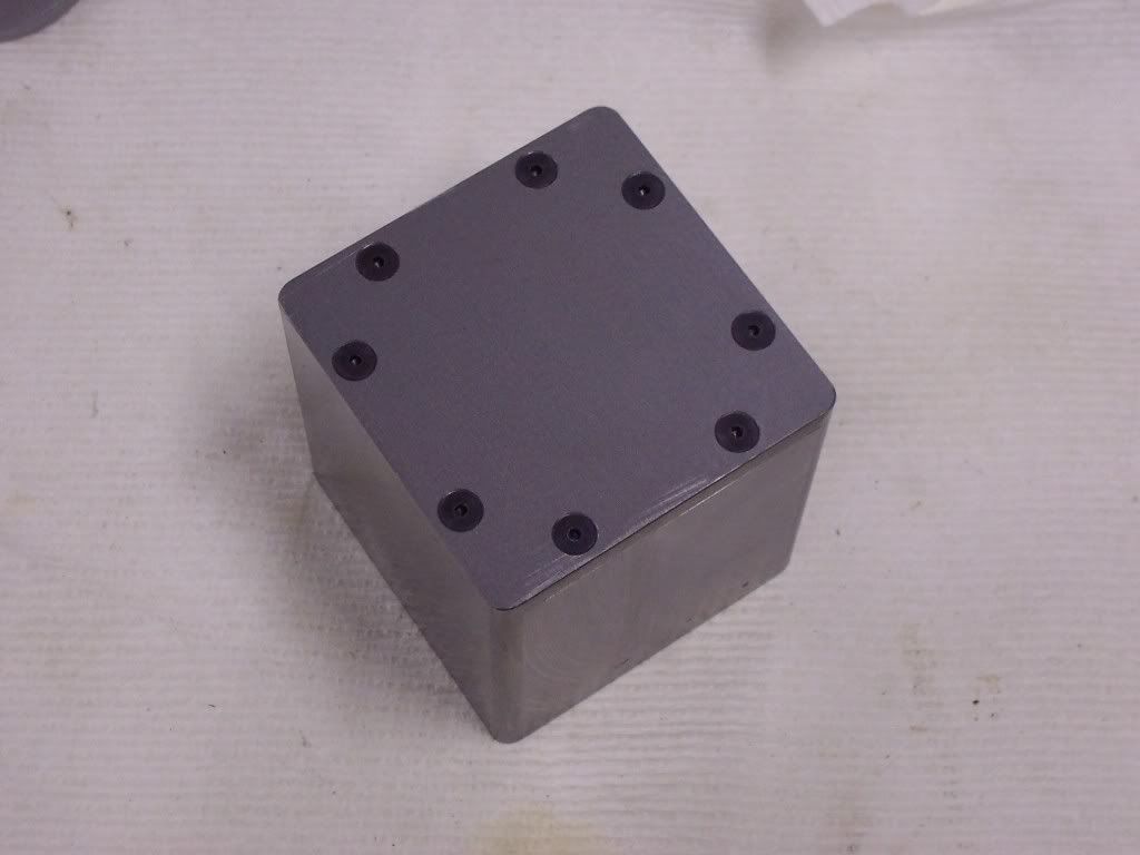
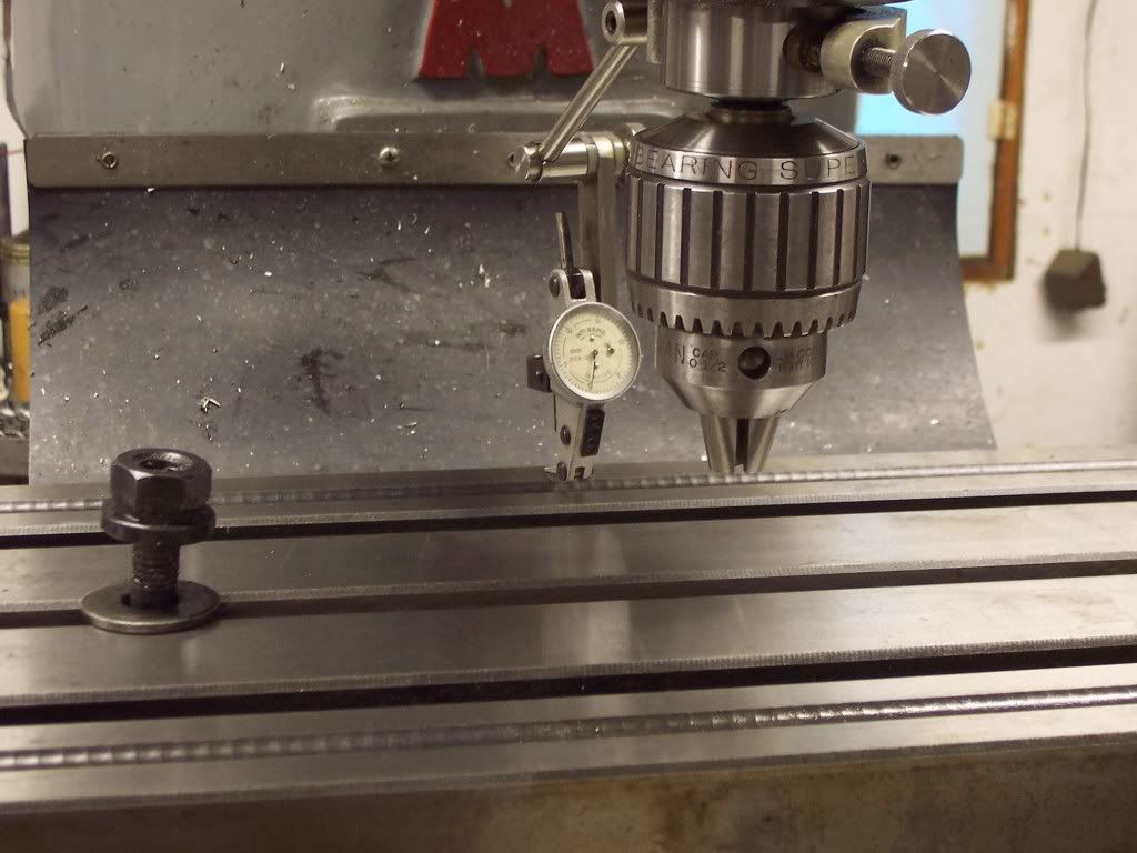
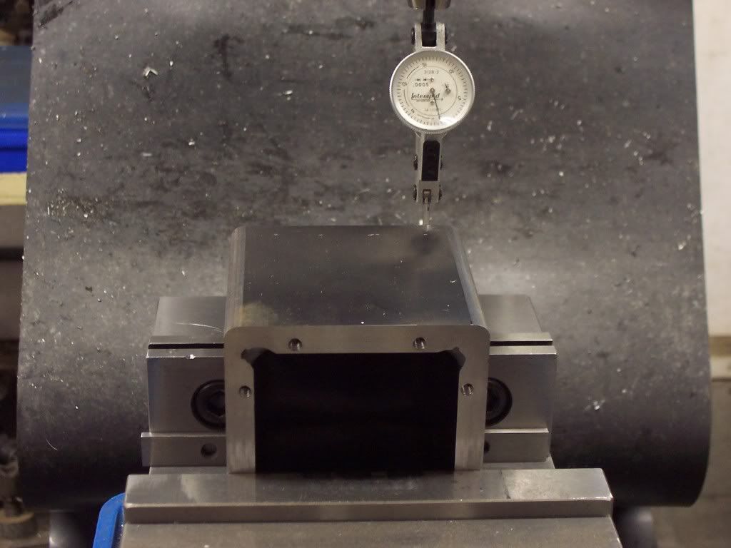
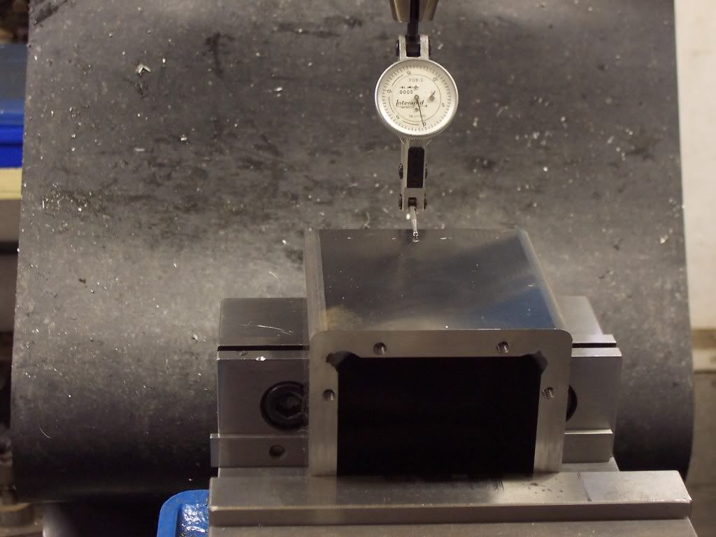
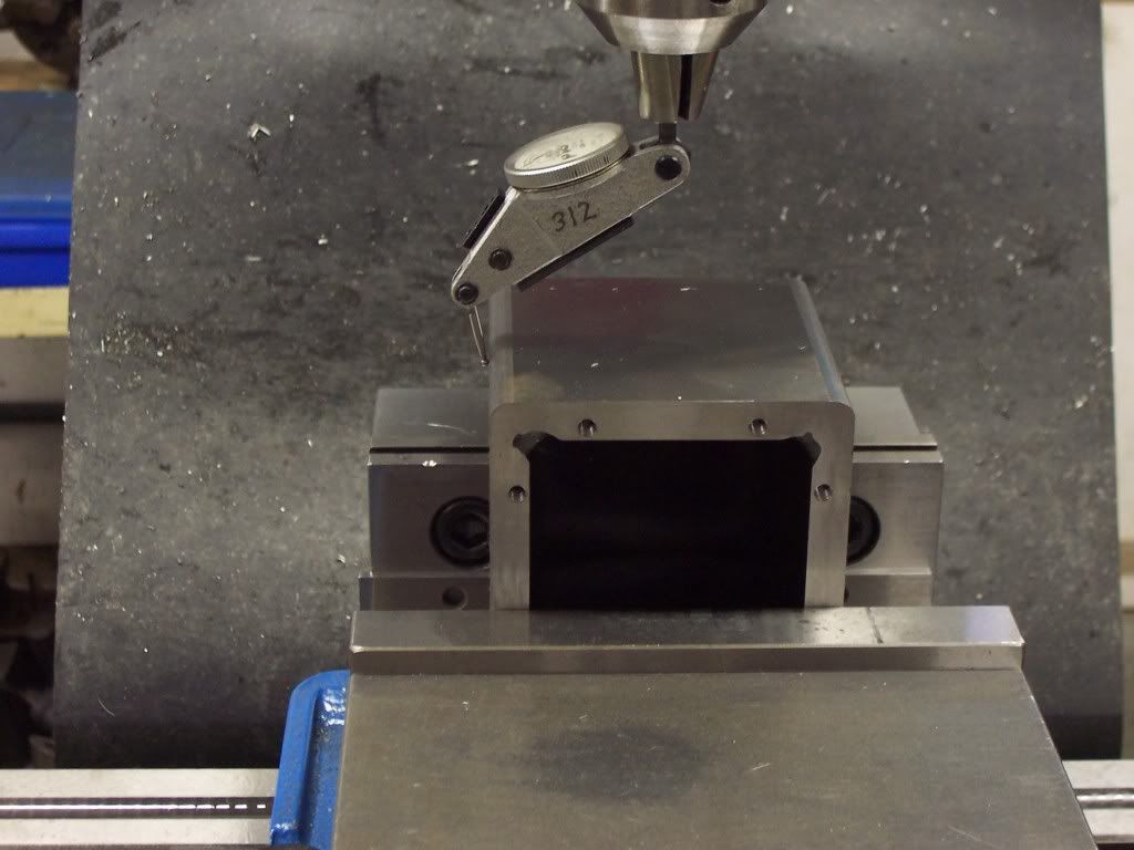
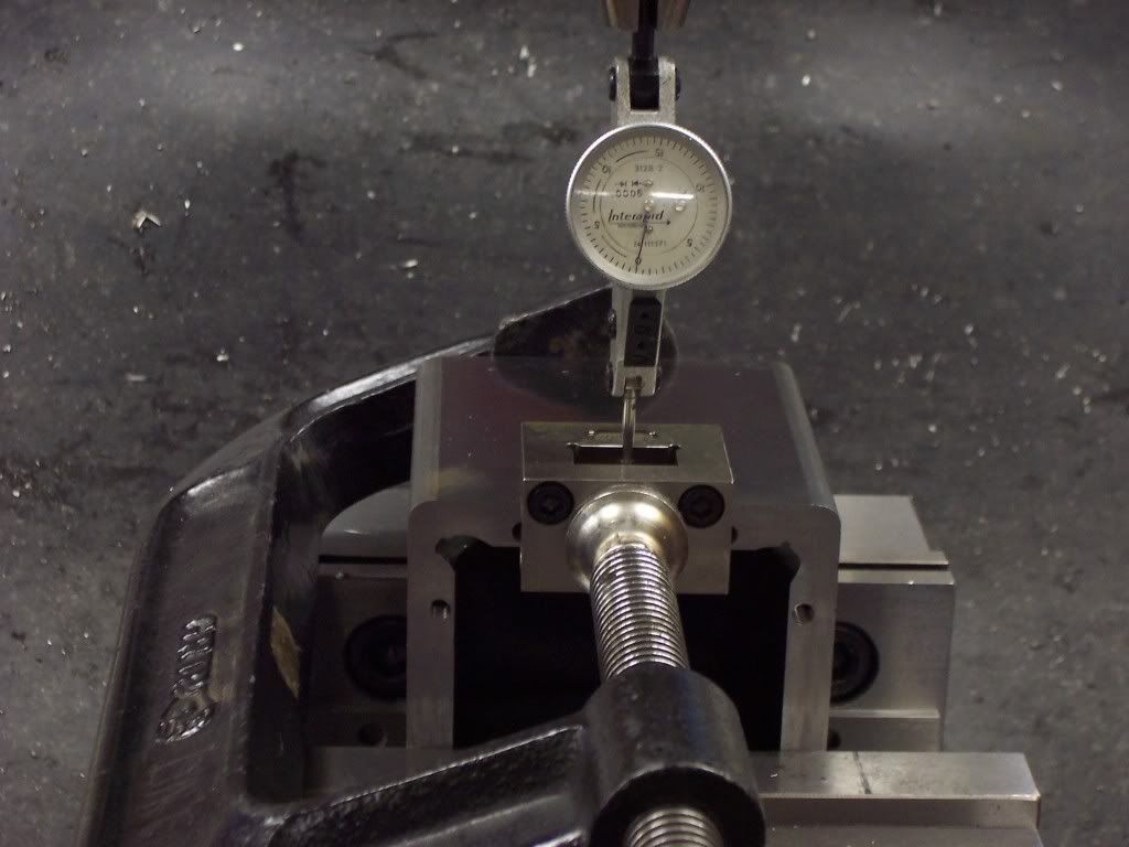
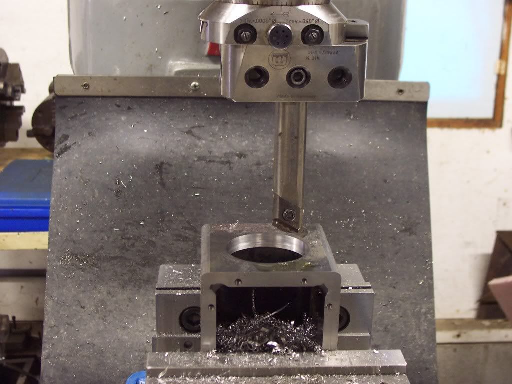
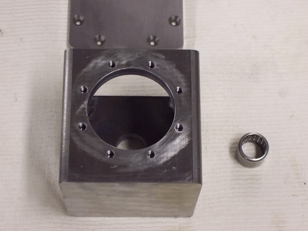
The gearcase needs 8 8-32 tapped holes put in the top surface for the top cover. This pic is of the gearcase set in the mill vise and using an edgefinder to find the left edge of the part.

102_1111.jpg


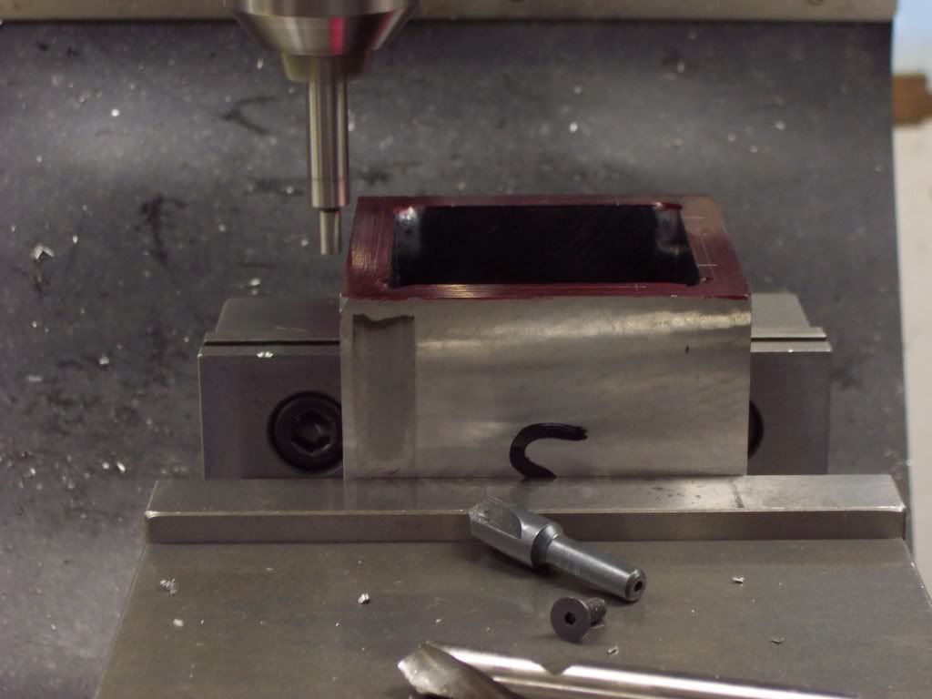
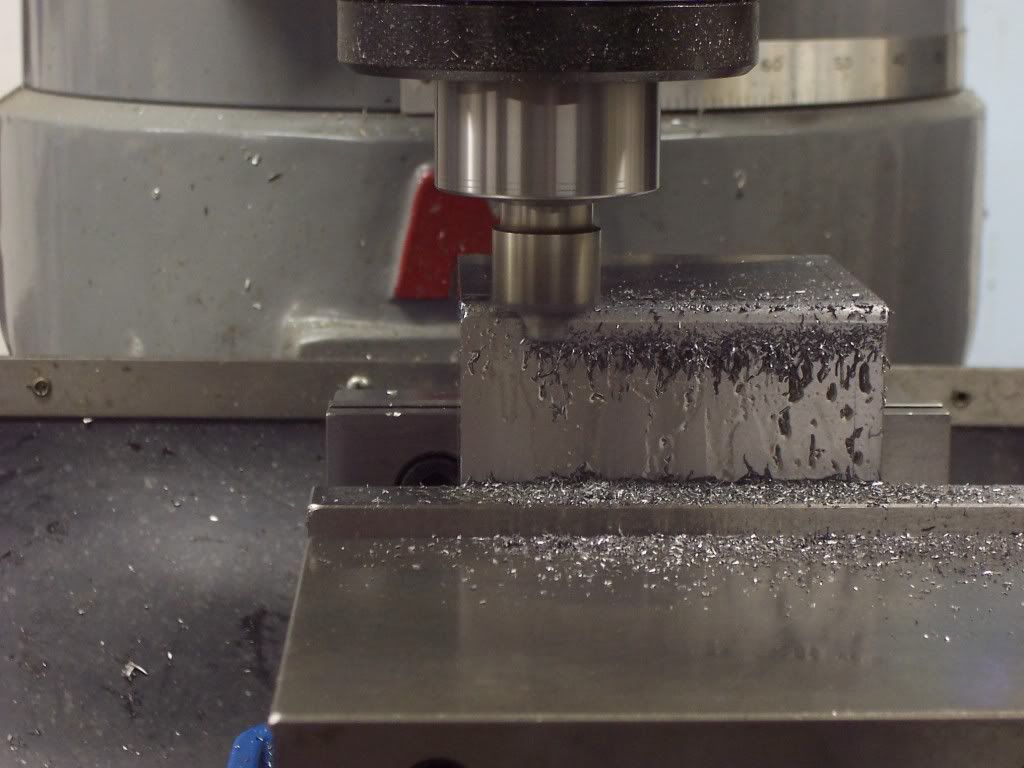
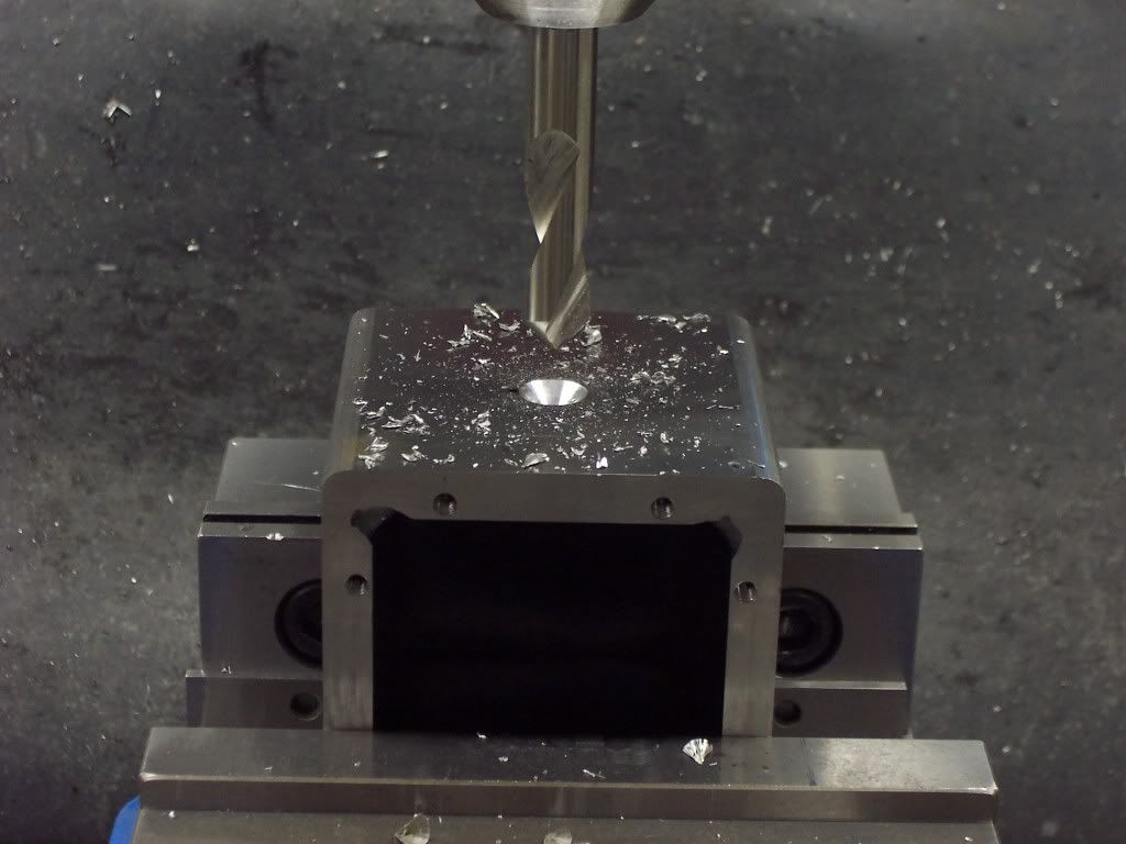
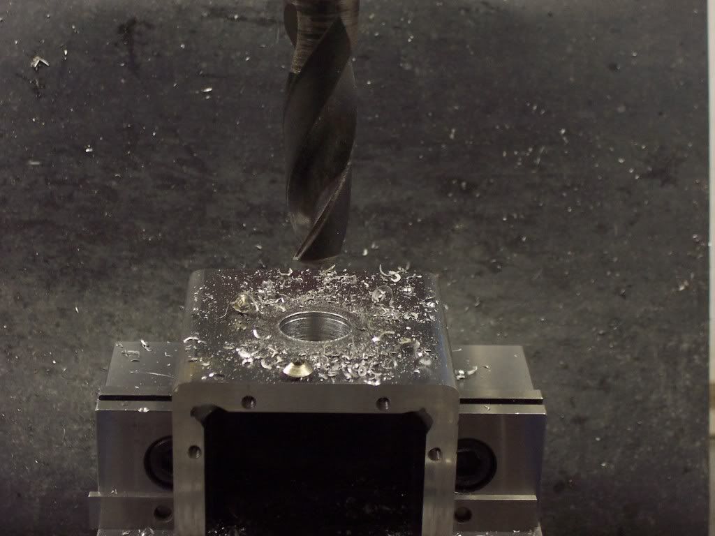
Spotting the holes with a spotting drill first.

102_1112.jpg


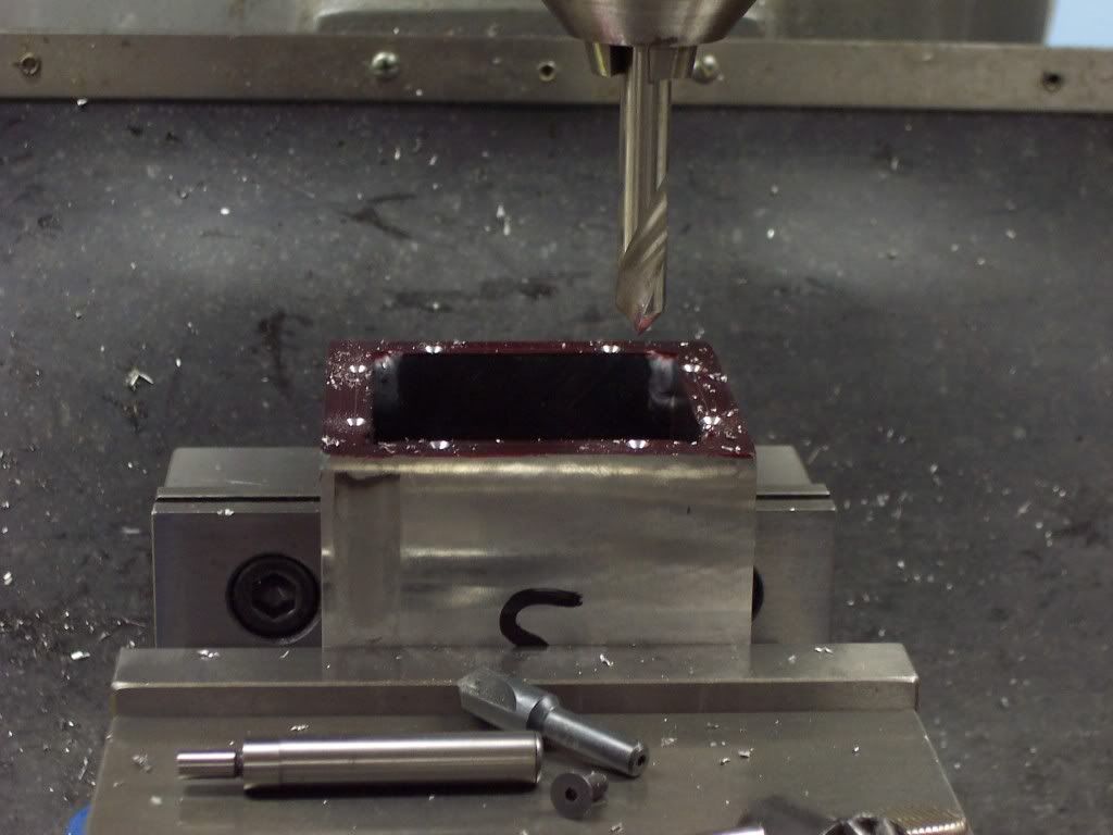
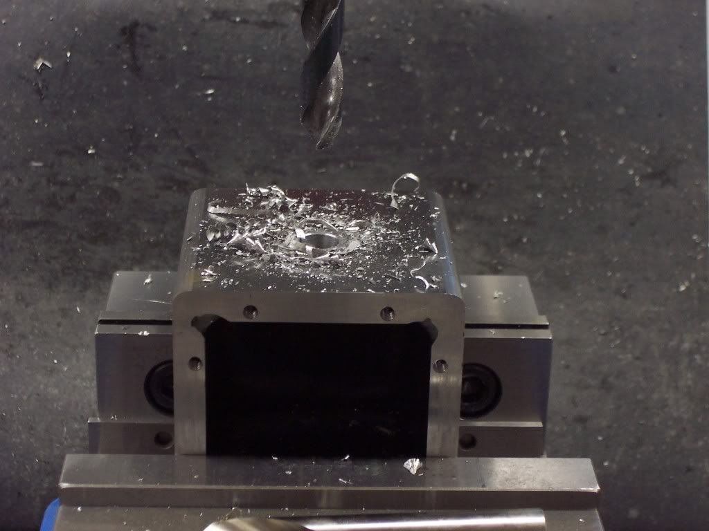
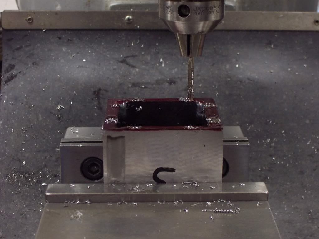
Then drilling with a tap drill.
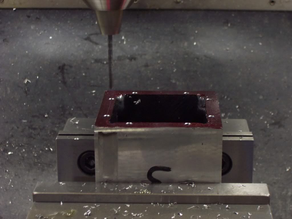
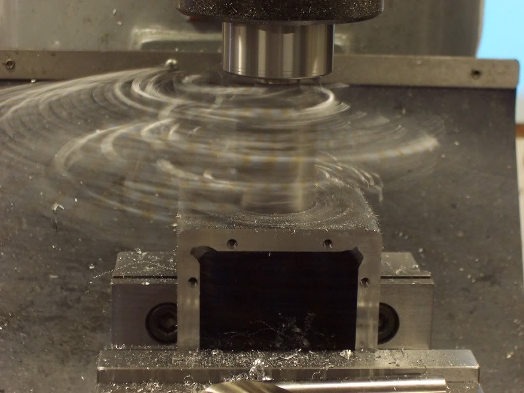
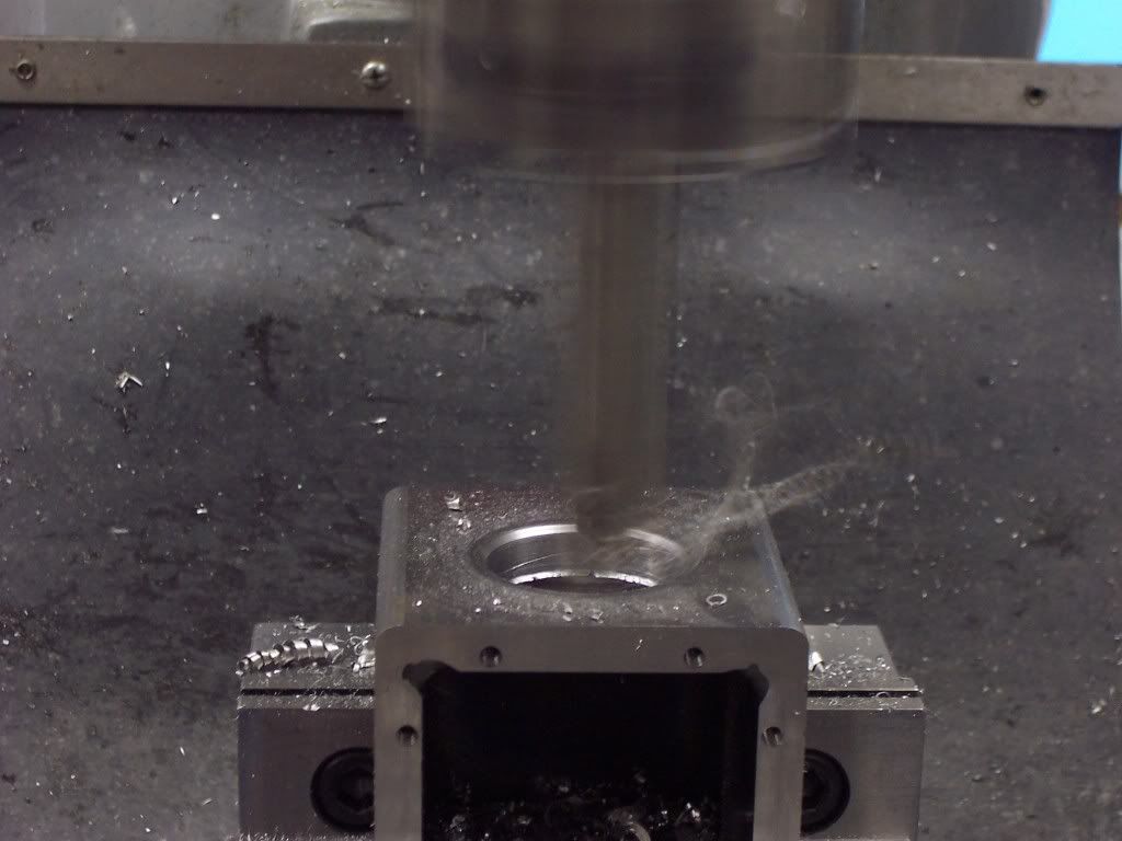
102_1113.jpg


Then tapping.
102_1114.jpg

 
We now have the top cover to the point where we can bolt it to the gearcase so we can surface grind the 4 sides of the gearcase to size. Once this was done the gearcase needed the corners radiused. For this I used a 3/16" corner rounding cutter.

102_1115.jpg


Here we have the gearcase finished ground to size with the top cover installed.

102_1116.jpg


Tomorrow I hope to be able to bore the holes for the bearing retainers. Once I have the holes bored and the mounting holes tapped I will be able to assemble this thing to see if the gears mesh well.
 
Hi Dave
Ill be following along for sure Buddy ;D
Pete
 
Hi Pete, I'm glad you're still with me. I hope this thing will start to look like an engine soon. I know this project is like walking into a room with the lights out for you guys but I hope when the light comes on you will enjoy the effort. Dave
 
Lots of techniques here that are new to me, and I'll take every metrology tip that you can give ;D

Thanks for the clear pictures and detailed explanation.

Simon
 
Hi Dave,

This is an interesting build and you are doing a fine job on the photos and explanations. Lots to learn in this thread. It appears you are using some sort of coolant or cutting fluid in the shot of the corner radiusing operation. What are you using?

Regards,

Chuck
 
Hi Chuck, thanks for the support. I am using Tapmagic on the corner round cutter. I have found that climb milling the corner cutter will give you a better finish. I will conventional mill all the stock off except for the last .005" in each axis and then climb mill the finish cut. Bear in mind that I use a Bridgeport copy that has very little backlash. I'm not sure how much luck one would have climb milling on a loose machine so be careful.
I am glad you are enjoying the build and I hope something useful can be gotten from the effort. My goal is to have this thing finished for Names 2012 so I will have something new to display. Dave
 
I had a little time today to do some boring. The first thing I did was to check the tram of my mill. Using my .0005" indicator in my indacol I swept the table anf found it was out .002" side to side. This was corrected and rechecked.

102_1117.jpg


Next I installed the vise on the mill and clamped the gearcase in the vise. Then I indicated the bottom surface and adjusted it until it was true.

102_1118.jpg


I then swept the surface that will be bored to make sure it was in the vise square.


102_1119.jpg


The hole for the flywheel bearing support needs to be in the center of the part in X so an indicator was used to sweep both sides and adjusted until the indicator reads zero on both surfaces.

102_1120.jpg
 
The hole now needs to be located from the top surface of the gearcase. For this I used my precision edge finder and my .0005" indicator. I could have used a standard edge finder but I thought the forum would like to see another option so I used the edge finder that we used to use to locate holes on a jig grinder. We used to jig grind alot of our tooling as the hole locations had to be held within .0002" - .0005" and the hole sizes also were just as close.

102_1121.jpg


Using a spotting drill to start our hole on location.

102_1122.jpg


Drilling a pilot hole.
102_1123.jpg


Using Silver & Deming drills to open the hole up to 1".

102_1124.jpg


The largest endmill I have is 1.375" dia so it was used to open the hole up even more by plunging.

102_1125.jpg


The finished hole size is 2.000" for the flywheel bearing support so I needed to bore the hole to size from here. Using a HS steel toolbit in my boring head I bored the hole in .10" increments until I was within .030" of final size.

102_1127.jpg
 
Before finishing the hole to size I removed the boring head from the spindle and replaced it with my drill chuck and used my indicator to check to make sure the part hadn't moved. Once this was confirmed, I finished boring the hole to size. Then the boring bar was used to chamfer the hole.

102_1128.jpg


After the hole was finished to size on the top surface I needed to bore a .8125" dia hole in the opposing surface in the same setup. This was done the same way as before.
 
Nice work Dave! Very educational and useful information.
Keep the progress coming, I like it a lot.

Regards Jeroen
 
Heres a pic of the gearcase with the first hole in it. In this setup I bored the 2.00" hole for the bearing support, tapped 8 10-32 holes for mounting, and bored a .8125" dia hole for a needle roller bearing in the opposing surface. After taking the part from the vise I checked the location of the hole on my surface plate by indicating the low spot of the hole and then flpping the part 180 and rechecking. I was pleasantly surprised by how close to center it was.

102_1129.jpg
 
I am absolutely mind boggled that you build an engine without any plan, making it up as you go along. it must work, for I know others do it as well, but I couldn't do that in a thousand years. I'm okay with simple parts that don't interact a great deal with other components, but something as complex as an engine-----no way.----Brian
 
I'm in the same boat Brian....I've tried it too many times and failed miserably ....every time!

Dave
 
This thing isn't running yet. I was leary of posting this build, it took a long time to convince myself to do it but I figured even if it were a failure, something could be gotten from posting the effort other than a black eye. I've done it before but I will admit this one is a little bit out there. Challenges keep me thinking and out in the shop away from the TV.

I finished boring the holes for the bearing supports in the gearcase today and after clean up it was assembled to see how my gear mesh was. Looks as though I will need to make a small adjustment in the gear depths but this I will do after finishing the internals of the gearcase. Heres a pic of the gearcase with the bearing supports in place.

102_1130.jpg
 
A pic of the cover in place.

102_1132.jpg


At the left end of the gearcase in this pic is the end of the flywheel shaft which will have a wheel with a magnet for the spark timing trigger. I will also use this for driving a water pump as it will be liquid cooled. This same end will get busy as there will need to be 2 holes bored for the roller lifters and the mounting holes for the cylinders attachment. If you haven't noticed yet, the crank disks will be rotating in opposite directions from each other. I think the next part I will make is the cam disk. This will be done on the mill using the rotary table. Since this engine has a bore of 1.250" I will make the cam with a valve opening of .125".
 
This is looking real interesting Mate
Two singles sharing a single flywheel, ignition and god knows what else :big:
This guys is how its done
The mind Boggles :bow: :bow:
Pete
 

Latest posts

Back
Top