I just tried the 9.5" diameter x 1" thick faceplate on the lathe, and the vibration is still the same at about 620 rpm. If I put one hand on the headstock and hold a good pressure against it, the vibration becomes much less. This leads me to believe that my chuck is probably not out of balance after all.---I think it has more to do with the cheap tin cabinets which the lathe is supported on than any "out of balance" factor in the chucks or faceplate. Probably I am just going to live with it. I know that a heavier, possibly poured concrete base would probably get rid of (or at least "soak up") the vibrations, but I will probably just leave things and keep my speeds below 600 rpm.

You are using an out of date browser. It may not display this or other websites correctly.
You should upgrade or use an alternative browser.
You should upgrade or use an alternative browser.
Cx701 lathe report
- Thread starter Brian Rupnow
- Start date


Help Support Home Model Engine Machinist Forum:
This site may earn a commission from merchant affiliate
links, including eBay, Amazon, and others.
ICEpeter
Well-Known Member
Brian,
It seems to me that what you are experiencing is naturally occurring resonance in that particular speed range when a number of factors come together to create this vibration. Most machinery (especially the lighter build machines we are using) have a resonance trigger level that occurs at certain points / speeds. The exception would be heavy build equipment with significant mass resulting in a low frequency resonance that would not be noticeable typically.
Peter J.
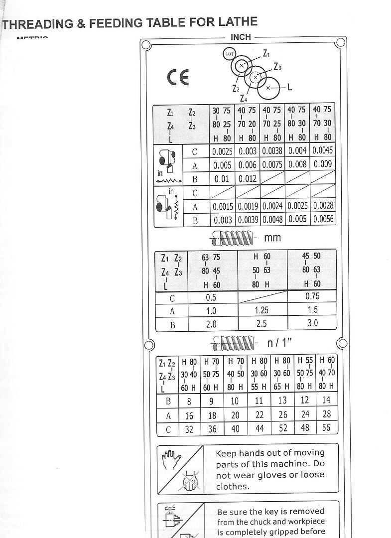
Okay--Let us leave the "unbalanced chuck" issue, as I agree it is probably harmonic resonance, a result of having a flimsy sheet metal base. My next "quest" is to figure out how to cut a thread with this lathe. I have never cut threads before---I know how to in theory, but not in practice. The users manual is for all intents and purposes "useless". It gives change gear charts that I don't know how to read. (That may well be due to my inexperience, rather than Chinglish manual.) I have determined that the lead screw is Imperial 10 threads per inch. I have found that the power feed handle on front left of the gearbox must be engaged and the power feed bar rotating before you can engage the "feed thread selector lever" on the right side of the gearbox to start the lead-screw rotating. I have engaged and disengaged the "half nut lever" on the front of the apron, and seen the carriage moved along by the rotating lead screw. I have a threading dial on the right side of the apron, which rotates when the half nuts are not engaged but stops turning when the half nuts are engaged. (I know there are rules that govern when the half nut lever can and can not be engaged depending on what number on the thread dial lines up with a pointer, but I'm pretty vague about that. I'm good with the cutting tool angle and position, I can read a thread gauge. My owners manual seems to have two charts for change gears, one chart having to do with travel speed of the carriage, the other having to do with the number of threads per inch I want to cut, but I can't for the life of me figure out how one relates to the other. If anybody has this particular lathe, and has successfully cut threads and knows how to read the change gear charts, I would sure appreciate some assistance.---Brian Rupnow

Last edited:
- Joined
- Dec 31, 2010
- Messages
- 783
- Reaction score
- 195
Hi Brian:
To avoid a long winded explanation. (ha ha)
At the top of your chart (next to the CE) is a diagram of what gears are what, and which gears need to be installed in which positions. Z1,Z2,Z3 etc.
First off I would see what you have in the various positions and stick with what you have. Don't make any changes for now. It's probably set for something reasonable. (but it could also be set for metric in which case only the metric thread charts will apply - see below)
At the bottom of your chart (above the warning hands) is a table of Threads per inch (titled as N/1). Looks like it goes from 8 in one corner to 56 in the other.
Find the column with the gear arrangement you have installed. It appears you will be able to cut three different threads based on one gear combination.
Apparently you have another selector that you haven't mentioned labelled A,B,C that will allow you to select one of the three possible threads.
(This seems pretty limiting. Usually a machine has a couple of other selectors that allow access to many many more threads with one set of gears. I've never had to juggle the actual gears on my machine.)
You said you already figured out the rest of the controls, so run your machine in back gear (dead slow). Mount a long bar between centers.
Put a pencil in the tool holder on center. Stay WAY back from the chuck.
Make some assumptions about what you are reading on the chart and run the machine to mark a thread line on the bar. (suggest starting with 8tpi) Measure the mark to get the threads per inch. You'll soon figure out whats going on. That's the safest way.
As for the threading dial. Rather than try to remember the rules about where you can can safely re-start the thread, I simply restart the thread at the same position on the dial every time. It takes a bit longer to wait for the dial to come around to the same number every time but I'm in no hurry and it gives some time to brush off the chips and apply some lube. For some reason my machine cuts crappy threads if I engage anywhere but the same place every time. (despite following "the rules")
You might have to get a feel for the engagement of the start/stop handle. On my machine there is definite feel for when it engages properly. It sort of "sinks" into engagement. Sometimes it engages but it doesn't have that feel even though the numbers line up. Apparently it's a bit off and the threads are a bit rough even if you make a second pass at the same settings.
Start with that. Not being in front of the machine it's hard to tell exactly what's going on from limited information. I trust you'll be able to figure it out.
Sage
- Joined
- Oct 1, 2010
- Messages
- 1,344
- Reaction score
- 396
Brian,
I'll second the "..You'll figure it out."
When I was sorting this out on my lathe for the first time, I made paper copies of the threading chart (see if you have it in whatever paperwork came with your lathe, or see if you can get it online.) with paper copies, in hand, I highlighted the results I wanted and the gears I wanted as well.
I never watched it until I had already learned the technique, but I can recommend mrpete222's video on external thread cutting.
On the resonance issue, I might suggest that perhaps attaching other materials (plywood, drywall, that stick-on insulation matting the car guys use, etc.) to large surfaces of sheet metal on the stand to dampen the vibrations could help. At the resonant frequencies, you might be able to feel vibrations with your fingers (it's that "mechanic's feel" thing) on parts of the stand. Or perhaps a mechanic's stethoscope with vibration-sensing contact would help locate the places you are looking for. What more can I say: You're a very skilled designer and you'll probably think of something.
Good Luck,
ShopShoe
Brian
I have the CX706 (smaller brother) and am also a noob to using it and cutting threads. One thing I noticed with mine. When I changed the gears to get the thread I wanted (1.25mm) setting the backlash was tricky, but more importantly, there seemed to be a ringing when the lathe was powered up and running. This was actually the gears making contact with the side of the adjacent gear on another shaft. It is almost as if the gears do not have enough lateral clearance at the teeth or conversely are slightly too thin at the hub. I might need to find some thin shims to go between the gears to prevent this.
Please let me know what you find with yours.
I've replied to Brian elsewher but this may help Sledjunk.
Ringing. If you look very closly at the washers that go between the banjo and the pairs of gears you will see that the are different thicknesses. If you position them wrongly the sides of the gears will rub each other, get them right and they will offset the gears jus enough to clear each other.
Backlash. Make up the gear pairs loosly on teh studs and then starting with teh one on teh leadscrew and next one up cut a thin strip of photocopy paper and feed that into teh gears as you work them together. It will end up consertina shaped. lock the stud with teh paper in place then wind it out. Repeat for the other gears and finally the gear that meshes with te spindle gear as you pivot the banjo back into place.
With luck these two things should give you quiet gears
J
In regards to the chuck vibration---I did as someone had suggested and put a piece of 3/4" round in the chuck, and drilled and countersunk it to accept the nose of a "live center" held in the tailstock. I set various and different preloads on the live-center to see what effect that would have on the spindle bearings. It made no difference. I still get the vibration at approximately 600 rpm. I conclude from that test that the spindle bearings are set properly and need no adjustment. If they had been loose, the application of different loads from the live center would have had some effect on the vibration.
- Joined
- Dec 12, 2012
- Messages
- 2,220
- Reaction score
- 1,285
H Brian,i had a similar problem with a similar chinese lathe I bought many years ago.To help alleviate the resonance problem I took a no of steps
If I recall my lathe was not bolted to the floor but sat on rubber waffle pads or isolation mounts on a substancial home made stand.Very stable.
I also fitted pieces of lead sheeting between the lathe feet and the stand
which were bolted.I also glued where possible sheets of insulation material
to the steel panels where I could Never fully solved the problem but did improve things.If I recall it was an early chinese lathe that weighed 300kg
If you have been using the lathe for a year or so, it is probably time you adjusted the headstock bearings - a very simple process as per the manual. The test you described with applying end thrust with the tailstock centre does not prove anything. It just moves any clearance in the bearings from the chuck-end bearing to the drive end bearing, which will still flap about.
Also, vibration could be coming from a loose drive belt - something else that will need adjusting after a year's use. And it could be coming from an out of balance drive pulley or out of balance change gears. All are easy enough to check.
The easiest workaround for flimsy tin cabinets is to make up some stands that go inside them with angle iron on each end so that one end bolts to the lathe base bolts inside the cabinet, the other end bolts to the concrete floor below. Two inch square tube works well for the stands, with 2 inch angle iron welded or bolted to each end. In effect, the stands support the lathe and the tin cabinet becomes an accessory merely for catching swarf and holding tools etc.
I made up a pair of these for my old lathe a while back and the transformation was quite surprising. Much smoother running and much smoother finish at all speeds. With a bit of ingenuity they can be tailored to fit under the lathe inside the cabinet where they do not interfere with storage in the under-lathe cabinets.
- Joined
- Jan 24, 2009
- Messages
- 554
- Reaction score
- 123
I'm with Hopper on that test; not completely valid for the problem presented.
Pete
Pete
- Joined
- Aug 7, 2014
- Messages
- 57
- Reaction score
- 68
Hi Brian,
I have a similar lathe model to yours, but the slightly bigger version, but mostly the same. It,s been mentioned already but the head stock bearings might require some "pre load" after a years use. To do this there are two nuts on the back of the spindle that lock as a pair.
By loosening the outer nut, this will unlock the inner nut, it's a sort of jam nut arrangement. Then very carefully see if the inner nut can be rotated towards the chuck, but, use a slightly more than hand tight torque so the bearings do not get damaged. Then tighten the two nuts together to lock them. I hope that might help any vibration. In an extreme case of head stock looseness, it might be possible to axially feel looseness.
The other tips on belt condition and looseness are also valid, a crack in the belt might cause a lumpy transmission that feels like an out of balance vibe.
The change gears are a real pain, every time I change mine for various threads, I have to muck about aligning the gears and using the supplied ridicules shim washers. I have no idea why these have not fallen out during use but if they are not set half right they make a terrible racket. In fact I have often thought of making a set of useable nuts and bolts for the change gears and if it's been done, then I hope this gets shared here.
The gears are fairly straight forward to work out, I always cut a thread on a test bit because it's easy to err with the gears and the lever's ABC setting.
Hope that helps
Steve
I tightened the locknut at the rear of the spindle a very small amount (after unlocking the two screws which are inset in to the face of the nut) and the vibration at the chuck has become noticeably less. Thank you to those who suggested it.---Brian
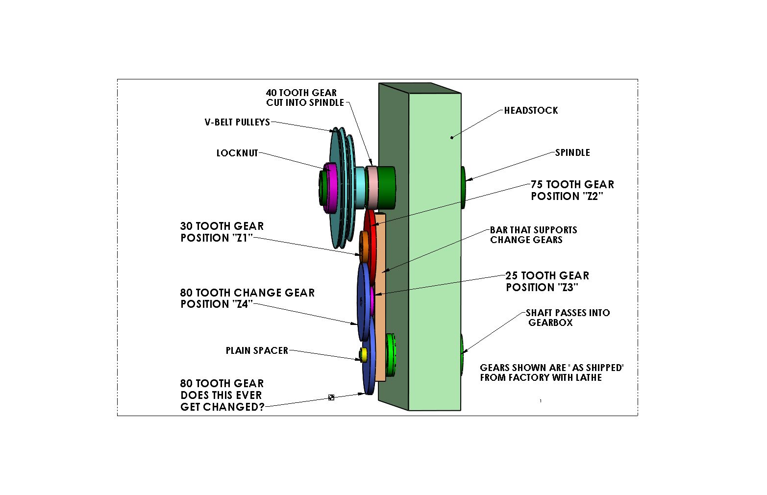
Some help if you would be so kind---Is it only the four gears supported by the bar in positions z1, z2, z3, and z4 that get changed or does the 80 tooth gear on the end of the spindle get changed also? The change gear chart I posted shows something called "H"---is that the plain yellow spacer shown in the picture?---or is it a different spacer? I have a couple of spacers with my change gears, one that has an external key milled on it, and one with an internal keyway. Could one of them be "H"? I want to cut an 10 tpi thread on a 3/4" shaft. My gear chart shows (I think) that position "z1" is occupied by "H", position "z2" is A 70 tooth gear, position "z3" is a 50 tooth gear, and position "z4" is a 40 tooth gear. It also tells me that position "L" which I believe to be the bottom shaft which extends thru into the gearcase as having an 80 tooth gear and also the mysterious "H". And I run the lathe at speed range "B' to do this. Am I anywhere close to being right?


Glad you smoothed those bearings down some. Try running the lathe at about 800 to 1,000 rpm for a half hour to warm things up then seat the bearing adjusting nut again. It might get rid of any remaining vibes.
Looks like you have the changegears worked out correctly to me.
The gear L (presumably for Leadscrew) would remain 80T in this case. Although, it looks like you change it to 60 to cut 8tpi etc, according to the chart.
I think it a reasonable assumption that H is the spacer. I have been trying to work out the Chinglish for that, closest I can come is H for "place Holder" or just "Holder"? Any spacer that fits on there to stop the gear sliding sideways will do the job providing it allows the 80T gear to be keyed to the shaft without interference. On older lathes it is common to use another gear as a spacer here, but it would have to be a small one in this case.
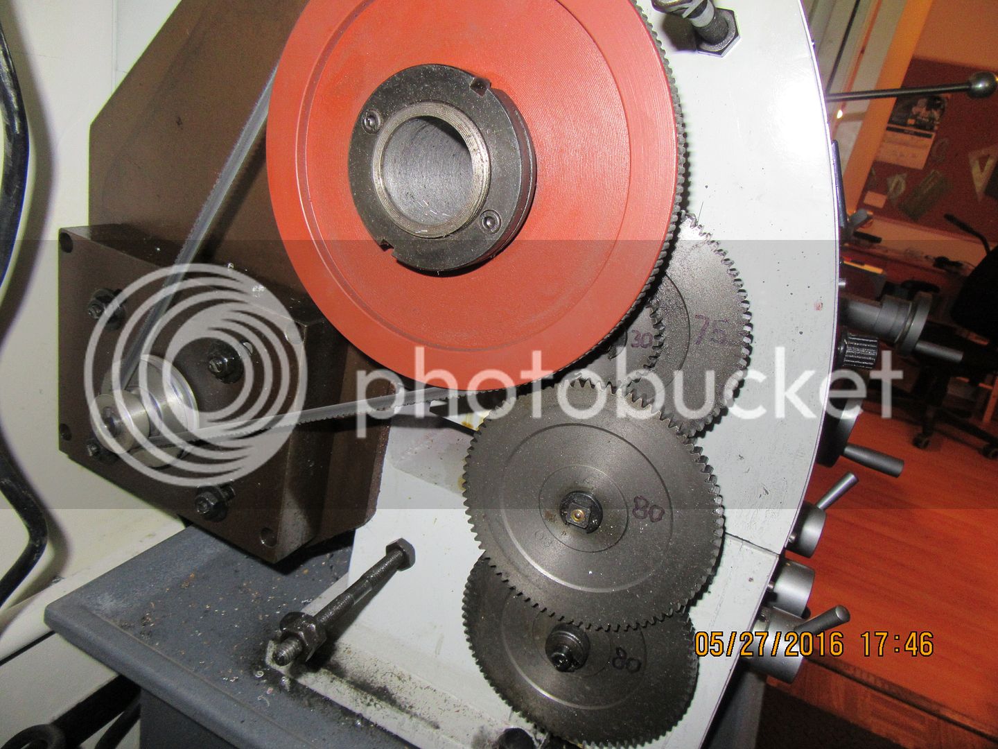
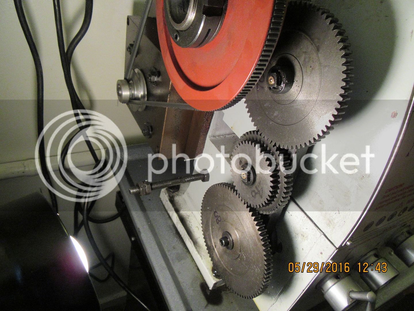
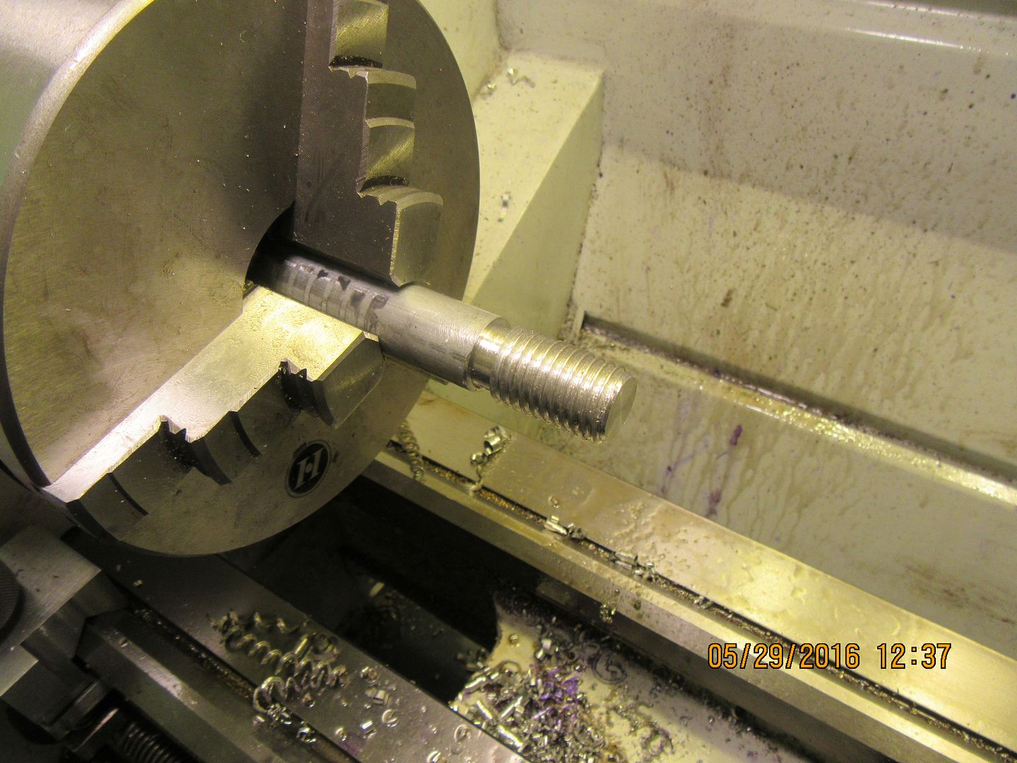
OKAY!!!---Great big hero cookie for me!!! First I made a lot of sketches and took a few pictures of the original factory set up of my change gears so that when I get finished this threading exercise I can return my lathe to it's factory settings. Then I set up the change gears to cut a 10 tpi thread. This looks a lot scarier than it actually is, but it certainly means a lot of studying the manual and interpreting Chinglish. It isn't as much a matter of the information being wrong as it is a total lack of information. This is what it looked like with the change gears set up for 10 tpi.

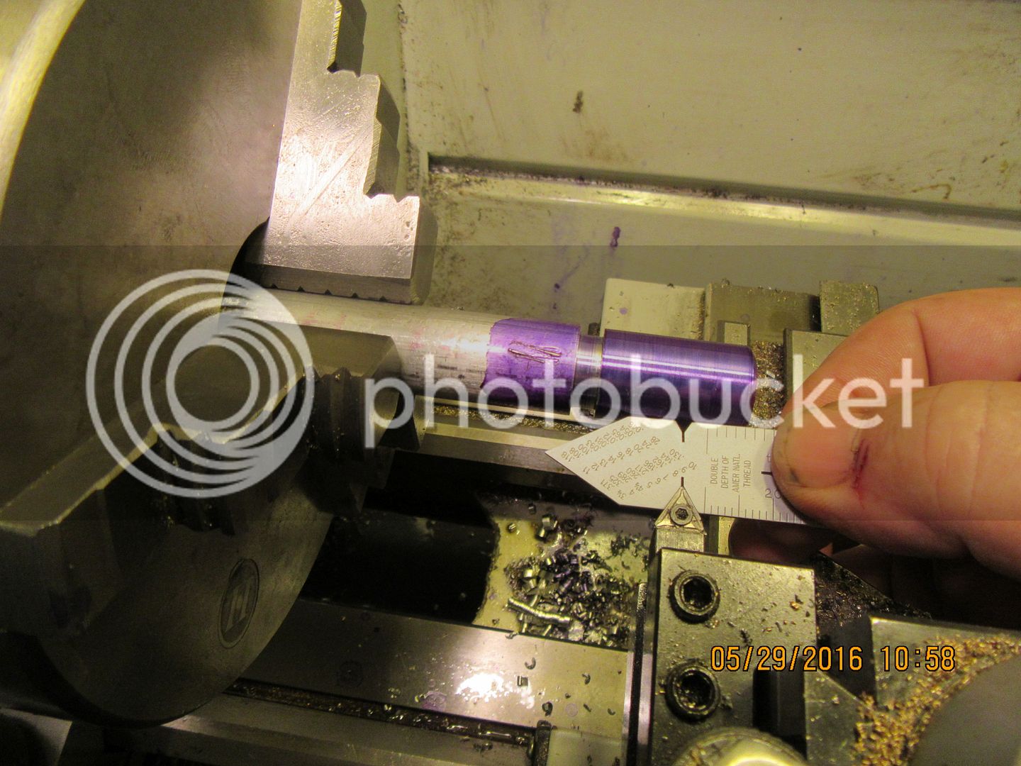
Next trick was to turn a relief area at the left hand end of what would become the threaded area to let the tool "run out" into the relieved area so I could release the threading lever and back out the tool. Also seen in this picture is my new "fishtail" setting gauge used to set the tool in the correction angular aspect to the part being threaded.

And with the cross feed dial set at "0" when just touching the part, and the compound rest set at "0" when just touching the part, and the lathe running at 120 rpm, I engaged the threading lever on the apron every time the "1" on the thread dial lined up with the indicator mark. I advanced the compound rest in .010" increments for each successive cut until I reached the required depth of cut. (There are charts for this depth of cut, but I found that I had to cut a bit deeper to let the nut go on freely.)

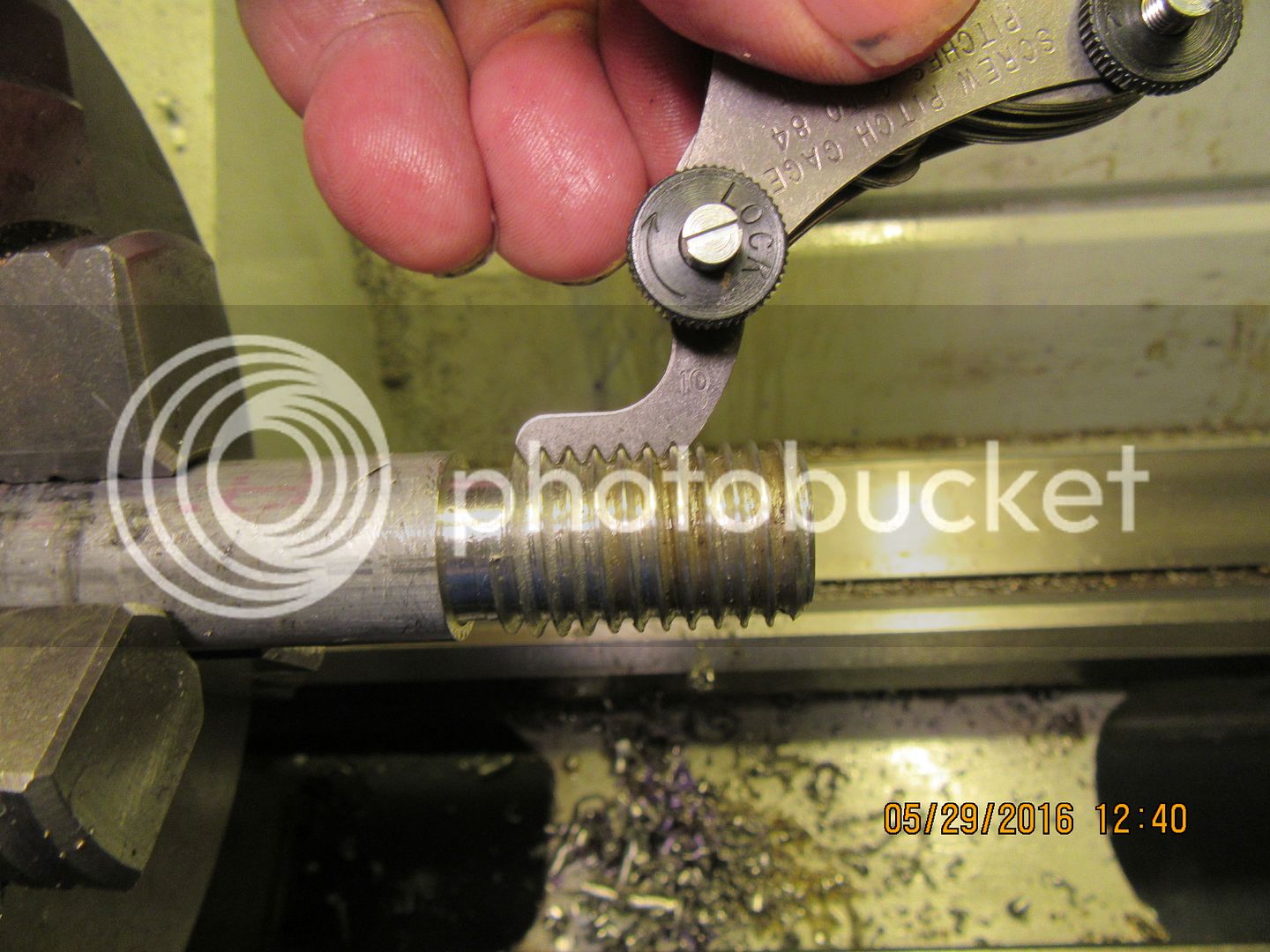
This is my new handy dandy thread gauge confirming that I had indeed cut a 10 tpi thread. Normally this would be done after the first light cut was made on the threaded part so you could correct things if it showed that you weren't getting the tpi that you expected. I managed to screw something up with that picture, so you get this picture instead.

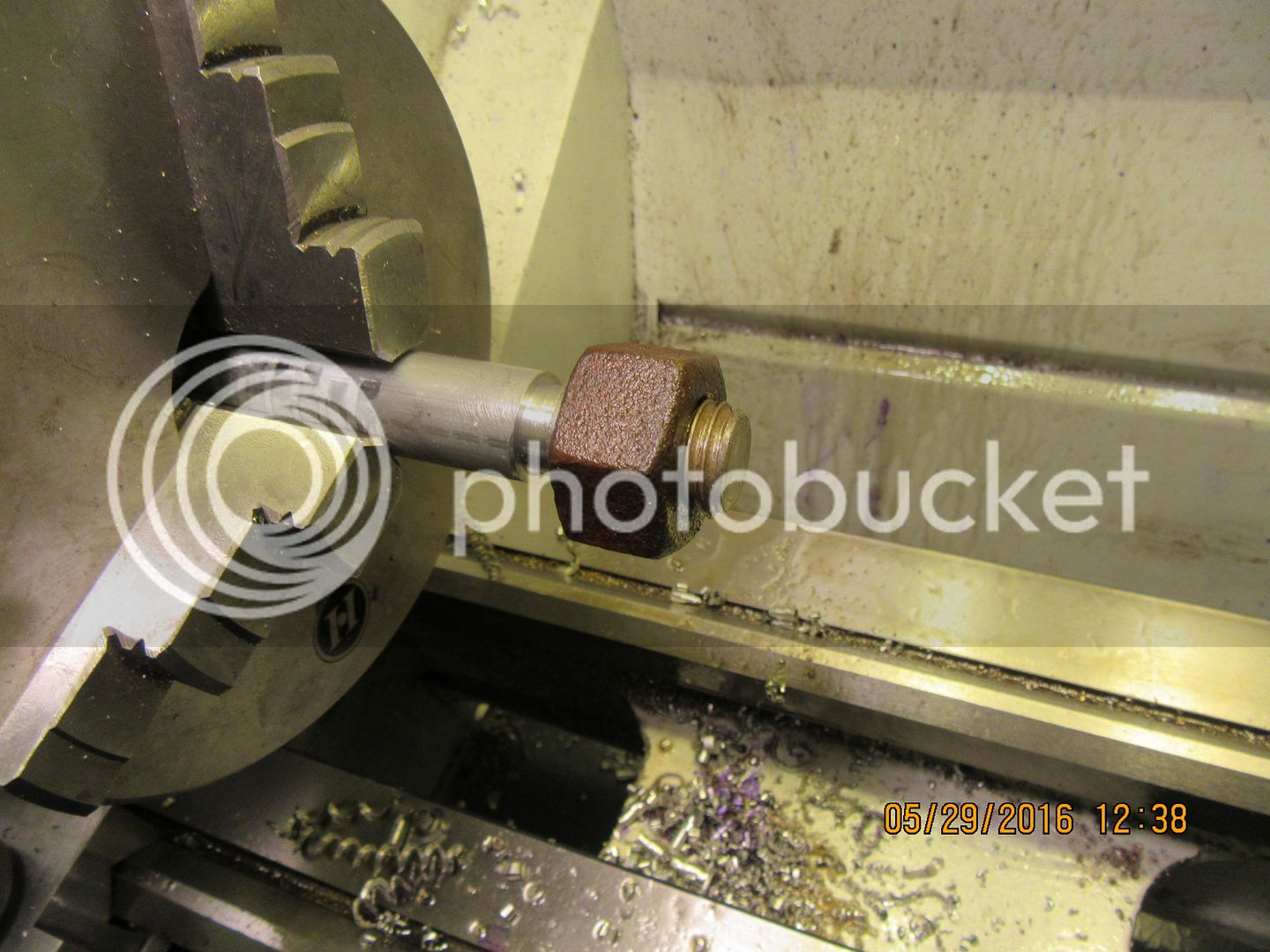
And yes, I dug around in my nuts and bolts drawer until I found this rust, crusty old 3/4"-10 tpi hex nut. It fits quite well. I "snuck up on" the last two cuts, taking about .003: each time until the nut would screw on.

Similar threads
- Replies
- 1
- Views
- 3K
- Replies
- 0
- Views
- 1K