- Joined
- Oct 20, 2010
- Messages
- 913
- Reaction score
- 132
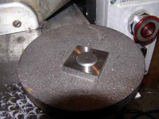
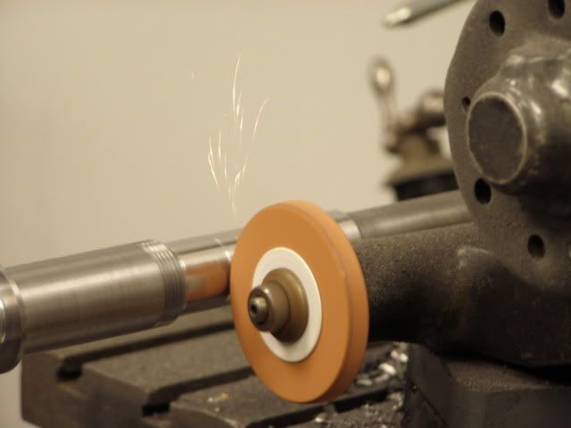
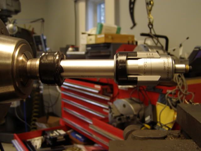
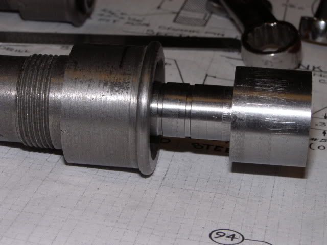
This will be my first model engine build, and rather than something simple, I thought a more challenging project would be right. So the casting arrived and appear to be nice material. Having turned some crap chinese cast iron back plates, I didn't know what to expect from these castings, the seller said they were cast USA but who knows. The first thing was to check out the flywheel, mounted it in the Monarch and give it a spin, the material cut beautifuly, nice finish no divots. After squaring up the surfaces, it was put in the drawer with the other iron lumps.
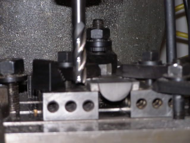
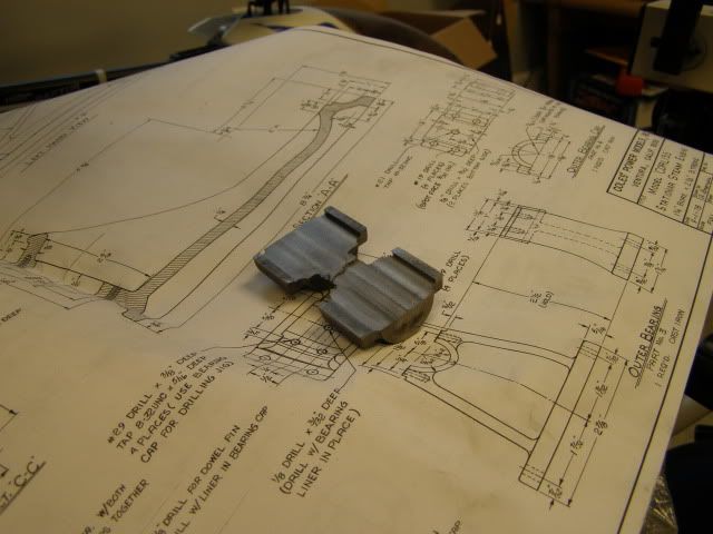
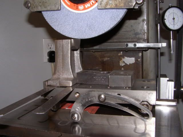
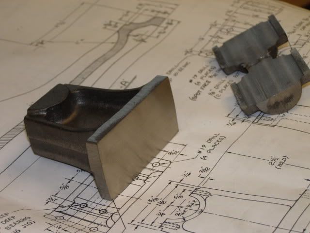
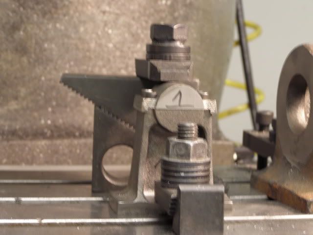
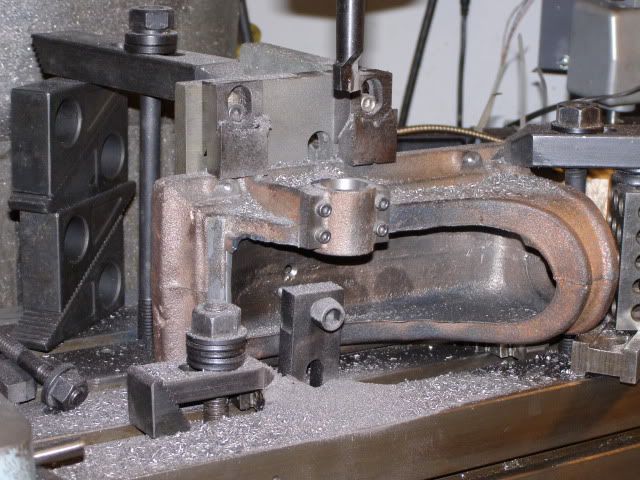
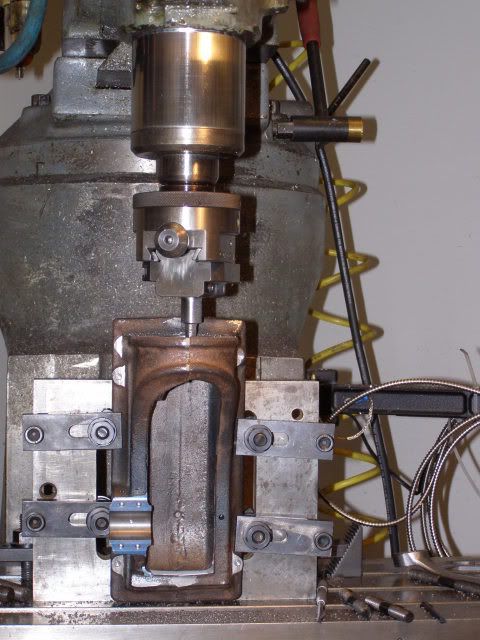
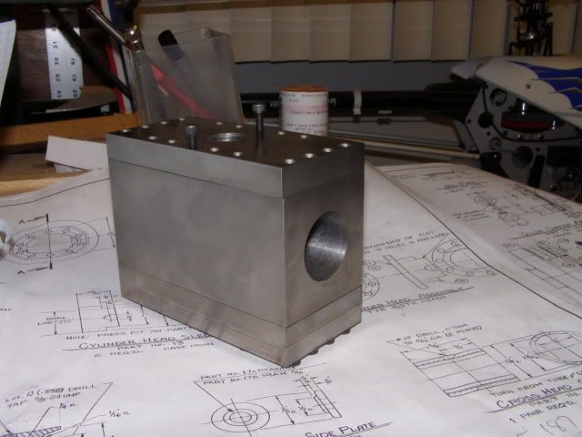
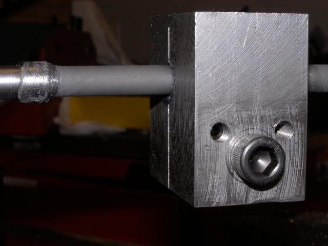
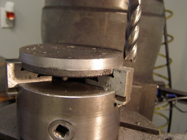
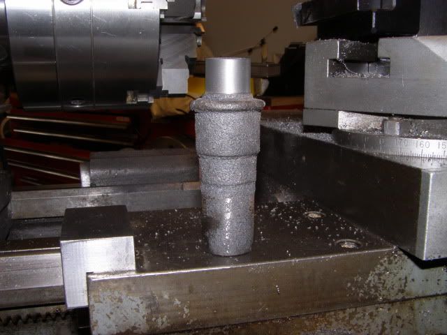
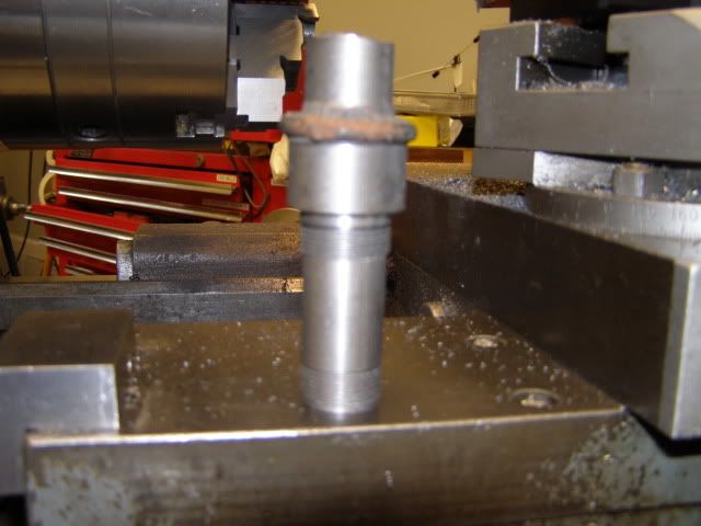
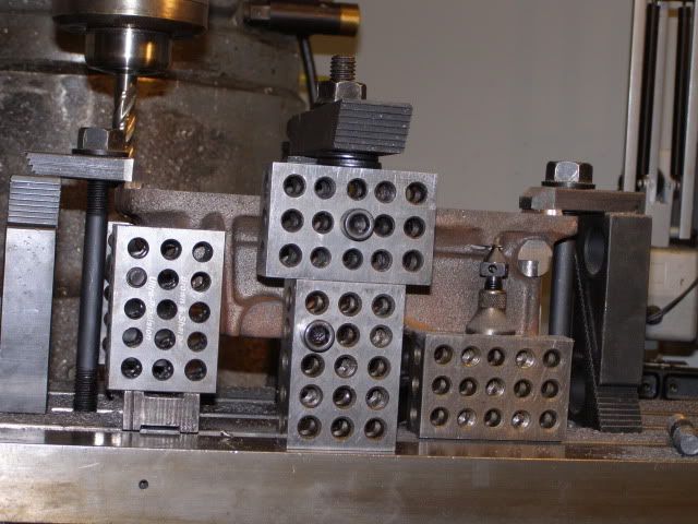
The Crankcase was next, the bottom was real rough with flash, so it was mounted about level using some cast in features that appeared to be even R/L. after trimming, that it was mounted bottom down and shimmed to bring the 4 mounting bolt bosses level, They were then spot faced, this would would serve as the datum to bring the bottom to size. The bottom now milled to size. These are the hold downs used for that operation, each end was held until final size, then a center clamp used to allow machining of each hold down area
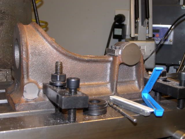
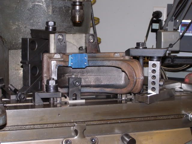
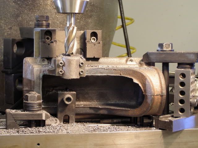
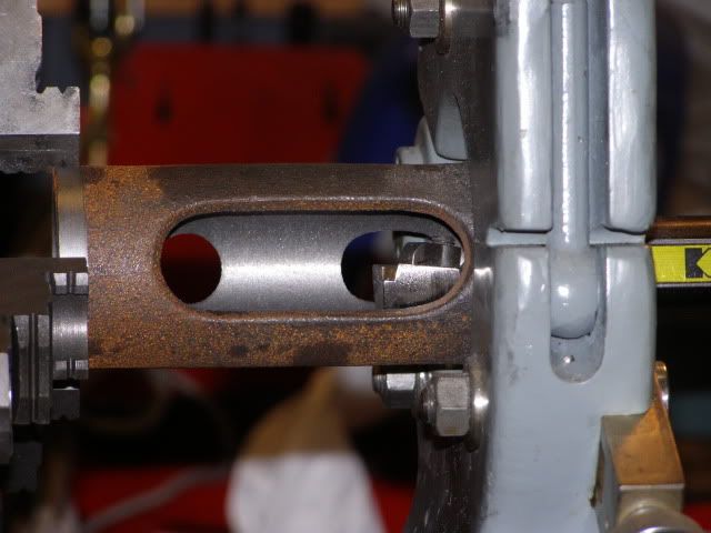
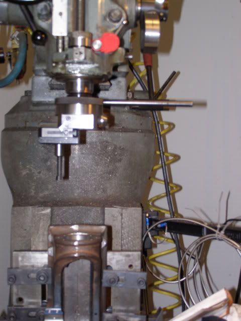
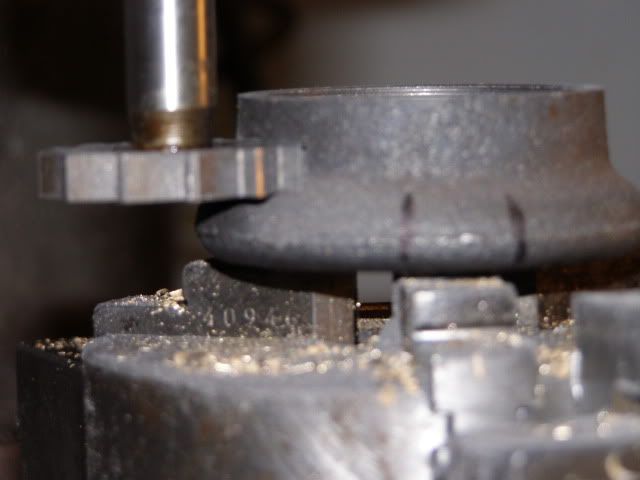
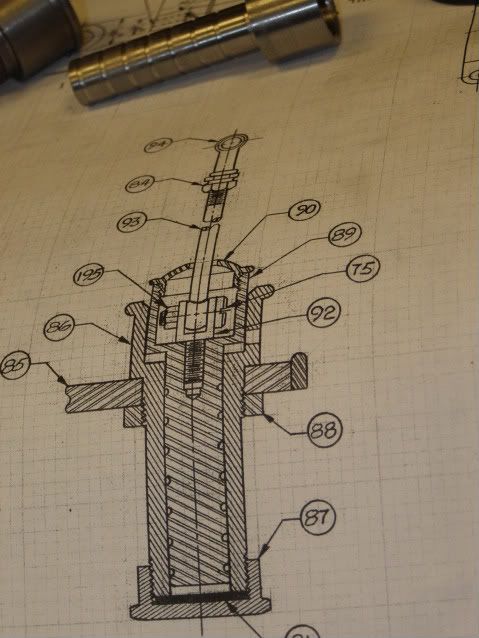
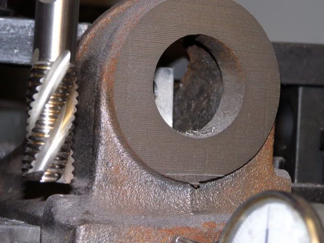
The drawing showed a center datum point positioned under the crankshaft centerline and all dimensions from that, so I centered the pillar for the crankshaft in X and the parting line of the casting is Y, before I drilled, picked a couple of the base mounting bosses check the measurments and things looked good. Proceeded to drill the mounting holes, main bearing cap holes all good, then I started facing the mount for the crosshead cylinder, at the point where the casting transistions from straight to the bead part of the casting, there is supposed to be a .060 area, nope all gone and the face is still .020 long, measured enough times and ways to know its what is there. Heres a shot of the face in the rough.
 ]
]
More later.
The Crankcase was next, the bottom was real rough with flash, so it was mounted about level using some cast in features that appeared to be even R/L. after trimming, that it was mounted bottom down and shimmed to bring the 4 mounting bolt bosses level, They were then spot faced, this would would serve as the datum to bring the bottom to size. The bottom now milled to size. These are the hold downs used for that operation, each end was held until final size, then a center clamp used to allow machining of each hold down area
The drawing showed a center datum point positioned under the crankshaft centerline and all dimensions from that, so I centered the pillar for the crankshaft in X and the parting line of the casting is Y, before I drilled, picked a couple of the base mounting bosses check the measurments and things looked good. Proceeded to drill the mounting holes, main bearing cap holes all good, then I started facing the mount for the crosshead cylinder, at the point where the casting transistions from straight to the bead part of the casting, there is supposed to be a .060 area, nope all gone and the face is still .020 long, measured enough times and ways to know its what is there. Heres a shot of the face in the rough.
More later.