Building one of Rudy's steamers

Home Model Engine Machinist Forum

Help Support Home Model Engine Machinist Forum:

This site may earn a commission from merchant affiliate links, including eBay, Amazon, and others.
It's a beauty, not much to do now, don't rush, you'll be there soon.

Nick
 
Should have just smoked the shaft with a candle in the first place.

Dean,
What's that about smoking the shaft?? Is that a solder resist method? Really enjoying (and learning from) this thread.
Dennis
 
You're doing a lovely job Dean - great progress :bow:

And like Dennis asked ?

Regards, Arnold
 
Mike, Tony, Dennis, Nick, Arnold; Thank you again guys, for your kind remarks and encouragement!

Nick, I've never been in much of a rush. That's why it takes me so long to get an engine done. ;)

Dennis and Arnold, by smoking the shaft, I meant use a candle flame to get soot on the part where I didn't want the solder to stick. Candle soot has a little grease in it, along with the soot. It will often keep solder from flowing to the part that is smoked. Like Dennis suggested, a solder resist.

There are other things people use to do the same thing. Maybe some are more effective. I come across one now and then, but I forget them. I need to write that stuff down..

Dean
 
Dean. Have you ever tried drawing a 'solder flow containment dam' with a soft lead pencil? I used this method with good results in the past to solder and braze.

Usually I forget and just roll the dice and regret. :big:

-MB
 
Hi Dean, I have a friend that does a lot of brass work. He uses a yellow ocher pigment to coat the parts he doesn't want solder to flow into or on. He gets it at the art supply store. I haven't personally used it but I have seen his builds and pictures and it works great.
gbritnell
 
some good tips there guys. we should all be producing neatly soldered joints soon then :big:
 
Metal Butcher said:
Dean. Have you ever tried drawing a 'solder flow containment dam' with a soft lead pencil? I used this method with good results in the past to solder and braze.

-MB

I've never tried that, MB. It's one of the ways that I've heard mentioned, but keep forgetting. Thanks for bringing it up! I have pencils!

George, thanks for the yellow ocher tip. Does your friend use just the dry pigment, or do you mean the oil paint that comes in a tube?
Thanks again.

Dean
 
Gosh Dean. You're really moving along. I can't believe how far back I was.
Fantastic thread. I am really enjoying it and learning a lot.
I appreciate all the great details as well as the additional tips from the other members.
Great brass work.

I noticed a holder (rods and brass fittings) that was holding a DTI about 3 pages back. Did you make that?
 
Hi Zee. Thanks a lot for your comments on the thread!
I'm glad to see the tips from other members, too.
You'll note I put in some of my goofs...

If this is the DI holder you mean, yes, I made it.
dithumb.jpg


Hit the link at the bottom of this post, and you will find it on that page somewhere
near the bottom. There's a short write-up for it, if you want to check it out.


Did a little work on the cylinder heads today.


216.jpg


They're mainly brass round things. Not LRT's, really. Medium round things.
Depending on your point of view.

Chucked up a piece of round stock, drilled and reamed where necessary.
Fun using the carriage feed on the Atlas to get this stuff down to size.
I might get spoiled.


217.jpg


Then, part 'er off, and make another one, similar, but different.

It's easy parting off stuff on the Atlas.
I'm gonna get spoiled...


218.jpg


Then flip the pieces and shape up the other ends.

Gosh, this was easy on the Atlas.
I'm spoiled!
...and too tickled to get any work done!


219.jpg


That's all that got done today.

Tomorrow will be hole drilling day, putting the mounting holes in the cylinder for the heads,
and if I don't goof off so much, maybe I'll get a little more done.

The new/old lathe actually distracts me, like when I was a boy with a new bicycle.
Then, I couldn't keep my mind on my school work. It's kinda like that. Silly.
Guess I'm still just a boy.


220.jpg


That's it for progress, today. Here's the "so-far" shot.

Thank you all again, for looking in on the thread.

Dean

 
Thanks Dean. Not just a tool...it's a good quality looking tool.

No cutting fluid when parting? Because it's brass?
 
zeeprogrammer said:
Thanks Dean. Not just a tool...it's a good quality looking tool.

No cutting fluid when parting? Because it's brass?

Thank you, Zee.
Yes, because it's brass.

Dean
 
Dean,
She's looking like a steamer. Keep the photos coming.
Dennis
 
Careful there Dean. That Taig might get a tad jealous and eat the next part or three you try to make on her... Hell hath no fury like a machine tool scorned....

:D
 
Really nice Dean. Is it all going to be polished or painted?

Nearly there!

Nick
 
Thanks Dennis!

Mike, I'm so attached to that little Taig... Nothing will take its place. And she knows it.

Nick, a little paint, lot of polish, and even a piece of, eh, wood.


Thanks for checking in, guys!

Dean
 
Dean, your moving along nicely!

In a previos post you mentioned paint, polish and eh, wood. Eh, wood? Do you hate working with wood the way I do? I don't get along with the stuff at all, and it seems to hate me. I use little touches like that to make my builds a little more attractive.

I'm anxious and can't wait to see your final picture post and video!

Humor; But don't go overboard with the "bling!." I don't need the competition! ;D

-MB
 
Wood?? :-X Pah!

I see there is a minimal amount of wood on the engine in your avatar! Wasted away at every opportunity!

Nick

 
Metal Butcher said:
Dean, your moving along nicely!

In a previos post you mentioned paint, polish and eh, wood. Eh, wood? Do you hate working with wood the way I do? I don't get along with the stuff at all, and it seems to hate me. I use little touches like that to make my builds a little more attractive.

I'm anxious and can't wait to see your final picture post and video!

Humor; But don't go overboard with the "bling!." I don't need the competition! ;D

-MB

Thanks MB!
Yeah, "eh, wood". I don't get along with it either, but it will make a good chicken coop, or a nice warm fire. 'Bout the most I get out of wood is splinters.
I'll never be a carpenter, that's for sure, anymore than I'll ever be a ballerina.
Just better at working in thousandths than in eighths, I guess.


Nick, sounds like you're in the same boat with MB and me.
That hunka tree under my avatar engine is just to keep the flywheels from draggin'!


Another slow day in the shop, but still a dab done. Dragging a bit today, coming down
with something. Probably caught it from Mike (twmaster). We hang out at the same forums..


221.jpg


This will be the gland for the cylinder head that carries the piston rod. A piece of 1/2" thick
brass was milled down to the called for 3/8", and chucked in the four jaw to be turned down
and drilled/reamed, as in the above picture. After that, it's removed from the chuck, and the
waste piece hack sawed away.


222.jpg


Then it's three jawed to clean up the larger flat on the other end.


223.jpg


The piece needs to have a couple of holes for the screws that will hold it into the bore in
the cylinder head.

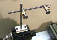
I have a simple stop pin indexing disc mounted to the drive pulley of the lathe spindle.
The piece has to have the holes on the center line of the flange. To get it lined up with one
of the indexing holes in the disc, the stop pin is put into one of the holes to lock the headstock,
then the chuck is loosened just enough to let me rotate the gland. I used a 1-2-3 block and
small square to get the top edge of the flange on the gland parallel to the lathe bed. Then the
chuck is re-tightened.

This looks kind of awkward, with only one hand holding everything, but normally would be
done with two hands. My other hand is holding the camera, of course.


224.jpg


Here, you can see the indexing disc and stop pin. I made this disc in the shop, but they are
available for purchase made to fit this lathe.

The holes will be drilled with an auxiliary spindle mounted to the cross slide. The center line
of the aux spindle is the same height as the C/L of the lathe spindle. It's also made so that
when its square to the cross slide, it is parallel to the spindle.

The gland has a 1/8" reamed hole through its center, so I put a 1/8" dia piece of drill rod in
the chuck to locate the aux spindle, then cranked the cross slide over to give the proper
distance for the holes in the flange.


225.jpg


After the holes are drilled in the gland, it was swapped out for the lower cylinder head, and
the matching holes for the gland were drilled. The aux spindle was left in the same spot as
for the gland to drill the two inner holes seen in the picture.

After the two inner tap holes are drilled, the cross slide is cranked out to put the remaining
holes in the outer bolt hole circle. When this is done, the upper cylinder head is put in place
in the chuck and holes on the same pattern are drilled. Then the two cylinder heads are used
to locate their mounting holes in the cyinder. And then, tap, tap, tap. Every other hole in the
bolt circle of each head gets tapped, and the two smaller holes for the gland, and the eight
mounting holes in the cylinder. Sixteen 2-56 holes, and a pair of 0-80's.


226.jpg


Here, things are being checked for fit. All these socket head screws in the heads and gland
will be swapped out for hex screws just as soon as I make them. The empty holes seen
here are for dummy cap screws. They show through in the space between the heads, but
lagging goes in there, so they wont be visible. The dummies will show on the outside, to fill
in the blanks between the real mounting screws. They're "pretend". Or, faux.
Genuine faux screws.

Thanks for checking in!

Dean
 
Boy that thing is coming along great Dean. I don't think Rudy had that amount of refinement on this project when he started it. It looks so good in the bare metal state it would almost be a shame to paint it. Keep up the great work.
gbritnell
 

Latest posts

Back
Top