Building Fred

Home Model Engine Machinist Forum

Help Support Home Model Engine Machinist Forum:

This site may earn a commission from merchant affiliate links, including eBay, Amazon, and others.
Nice Arnold.
I can understand wheels getting stiff from loctite...but the assembly warped? What would cause that?
 
Ah man Arnold, you do have the patience of a saint (and I'm not saying which one ::) ) to overcome all of the tribulations such as these. Well done and I do so enjoy watching as you progress through this build. I have confidence that this will turn out to be a real winner. BRAVO!

BC1
Jim
 
Hi Arnold. Glad to see another episode on ol' Fred!
We all have a hard day of it now and then. I know you'll get it sorted out.

On using aluminum for the rigging of parts to be soldered;
Aluminum conducts heat like mad, and will draw the heat out of your work piece until it's saturated. You know what happens next.
Steel will not absorb heat as fast, and will make a better jig in that respect. But, then you have to be careful not to solder the work piece to the jig.
You may already know that stuff, but someone may find it useful.

It's a great thread. Arnold and Fred.

Dean
 
Rob, Zee, Jim, Dean - thank you for checking in :)

Rob, thanks very much mate ;D; I'm getting used to those 10BAs now; anything smaller I can try :big:?

Zee thanks! The assembly was made weeks ago already and loctited; it was running very smoothly in the frame. Attached is a C-O-C :hDe: of the assembly; might help to picture it. When making it originally, the center shaft ran all the way through, and was cut out from between the wheels and webs after everything had set. The loctite came loose where indicated with my fiddling yesterday, and as a result the "center" shafts that go out from the wheels through the bushes in the frame is out of alignment. I'll just completely disassemble and re-do it.

Jim, thank you for your confidence. One thing I have learned over the years is that it does not help to toss toys when things go wrong; just pick up and carry on and learn from the process :) I think I'd be bored dead if unexpected things didn't happen.

Dean, thank you :) ; yes, I didn't want the parts to stick to the jig and I wanted the solder to flow in and fill the back edge between where the bend is in the angle and the bottom of the upright. In this case, there was definitely too much aluminium, and I think I was over-eager with the torch heat as well ;) I also forgot I was using the higher temperature silver solder I have; If I went for the lower temp solder, I wouldn't have had the problem - I think!

Regards, Arnold

wheelassy.jpg
 
Arnold,

Whenever I make a built-up crank like that I only depend on the Loctite to hold everything in position while I drill through and install pins, either solid or roll pins.
(I learned to do this when my Poppin crank disassembled itself after a lengthy run at an exhibition.)

If your soldering jig is something the solder will stick to (e.g., steel), try smoking the relevant area. An acetelyne flame is often used but I've used a candle flame or an oil lamp with too much wick exposed.

I've read, though never tried, typewriter correction fluid will also prevent solder from attaching. However, who still has a typewriter?

BTW, congratulations on being one of the ten English speaking people on the planet who use 'loose' and 'lose' properly. It's a very select group. :)
 
Ha!

My dog got loose, but I didn't lose it.

That makes 11.

Dean
 
That's a loose interpretation if ever I saw one, much more of that and I'll lose the plot completely!
 
mklotz said:
Whenever I make a built-up crank like that I only depend on the Loctite to hold everything in position while I drill through and install pins, either solid or roll pins.
Thank you Marv. Yes, from Dave's build log, that's exactly what he did - after his assembly was dropped and came apart. I considered it. I could not find 3mm drill rod for the shafts locally, so all the shafting is from piano/music wire. I didn't want to try and drill it for pins, as I am not sure whether a normal HSS drill bit would do the job. Another concern would be the drill wandering and breaking in the brass middle section once the piano wire is encountered.

If anybody knows if it is possible to drill the music wire for the pins, that would be a great help.

Annealing the piano wire is also an option, but I don't know how likely it is to warp. On the other hand, silver soldering the assembly might also cause warping...

I do have some 4mm silver steel; turning a sufficient length of it down to 3mm is a bit daunting still. But maybe it's time I tried my traveling steady ?

I REALLY need to set up a computer in the workshop for quick reference back to the tips. Dean also suggested the candle smoking on his thread; I even quizzed him about it... :-[ I have tried the error correction fluid; that worked to an extent, but started coming off at heat, and the flux seemed to still neutralise it a bit. Some experimentation is definitely in order!

And one for the loose cannons ;) - after I had a good laugh!: First there was 10 (some translation), then Dean made it 11, so that means Tel made it 100 ? (I'm a bit binary minded - only 2 brain cells)

Regards, Arnold
 
arnoldb said:
:-[ I have tried the error correction fluid; that worked to an extent, but started coming off at heat, and the flux seemed to still neutralise it a bit. Some experimentation is definitely in order!


Regards, Arnold

You were probably using today's politically correct water based stuff - Wite Out works a treat, but it has to be the old spirit based stuff
 
Thanks Tel, yes, I was using the latest shop bought stuff - "they" just don't make it like "their parents" used to, do they ?

Dang, and the compiler picked up a syntax error - Thanks Vernon

Regards, Arnold
 
Really nice set of cylinders there arnold. I had one of those cross vices once but it broke. I didn't think much off it at the time, probably because I thought I could mill with it (I was young and stupid) but now it looks quite useful for drilling.

Nick
 
Merry Christmas everyone!

Thanks Nick :) - Yes, that cross-vice would be useless for milling, but in the drill press it is a really handy tool. In fact, I very rarely remove it; only if I need to drill something bigger than what it can handle, or that is awkward to clamp in it.

On to Fred ;D
This morning, I disassembled and cleaned the cranks/wheel assembly and cut a new piece of piano wire for the main shaft. Then cleaned everything very well, and assembled with flux on all the shafts. I took some time to clean off excess flux from where I didn't want it - on the shafts where the big ends connect and outside the wheels . Then using the oxy-butane welding set, with the flame set to an orange smoky flame, I gave everything a quick once-over - left a black deposit on most everything. Then I turned the gas up to a nice blue flame, and silver soldered it with tiny dabs of the rod, using the flame heat to draw the solder. Worked a treat :) - had very little excess to clean off, but everything soldered up really well. I can kick my own butt - I didn't take photos.

Then dumped the assembly in citric acid to pickle. While waiting for that, I made the new 2mm longer con rods.

This afternoon I cleaned up the wheel assembly. The pistons were a bit tight in the cylinders as well, so I removed the O-rings for now.
Then reassembled the whole lot and did a trial run on 5 psi compressed air.

[youtube=425,350]<object width="425" height="344"><param name="movie" value="http://www.youtube.com/v/D_2njB1ykxE&hl=en&fs=1"></param><param name="allowFullScreen" value="true"></param><param name="allowscriptaccess" value="always"></param><embed src="http://www.youtube.com/v/D_2njB1ykxE&hl=en&fs=1" type="application/x-shockwave-flash" allowscriptaccess="always" allowfullscreen="true" width="425" height="344"></embed></object>[/youtube]

Looks like it'll work ;D - has good torque at 5 psi, and with increased pressure, I can barely stop the wheels.

Next up, some boiler making....

Regards, Arnold
 
It certainly does look like it will work!
Good work, Arnold. Runs very nice, and the reverse valve works great.

Merry Christmas!

Dean
 
Ooh! Ooh! Now doesn't that look great! It seems to run extremely well without the O-rings. Should go a treat on the track under steam pressure.

BC1
Jim
 
Merry Christmas, Arnold.
A run like that makes a nice Christmas present. Thm:
Gail in NM

 
GailInNM said:
Merry Christmas, Arnold.
A run like that makes a nice Christmas present. Thm:
Gail in NM

And Happy New Year. Looking good. :bow:

Best Regards
Bob
 
arnoldb said:
I can kick my own butt - I didn't take photos.

Please take pictures next time. ;D I have my own technique but am willing to learn new.

Looks great Arnold. Can't wait to see the build pics on the boiler.
 
Dean, Jim, Gail, Bob and Zee - thank you so much for checking in, and your kind comments :)

I was actually surprised the engine ran that well; It's still leaking air a bit from the bottom cylinder heads, so I'll have to make gaskets for them, and I didn't even use packing nuts and packing on the con rods - still have to make those as well... The spring on the reverse valve is a bit soft; I had a bit of leakage there as well, so that will need a slightly stiffer spring :) - but all-in all, a good result, and a good Christmas present!

Zee, today I took more photos ;D

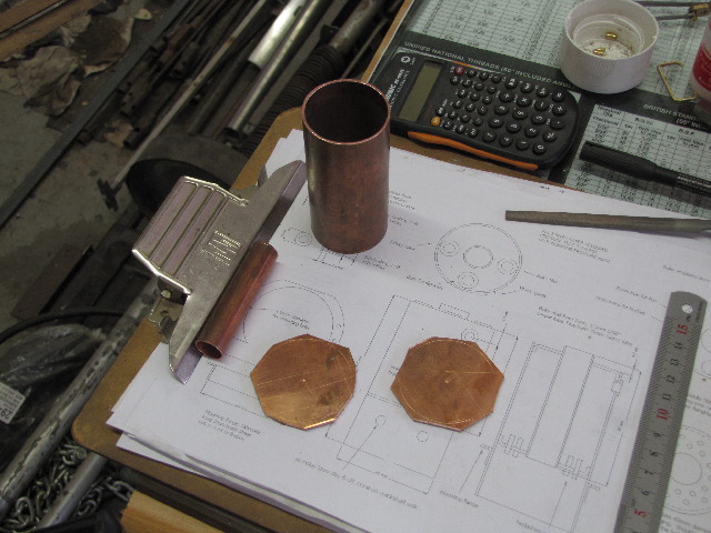
This morning I started with bits of copper. I have never really worked with this metal, so this is pretty much an all new experience for me. A piece of 42mm tube 1.5mm thick for boiler shell, a piece of 15mm tube for inner tube, and two pieces of 2mm thick copper plate for the boiler end caps; roughly sawed to shape:
s0295.jpg


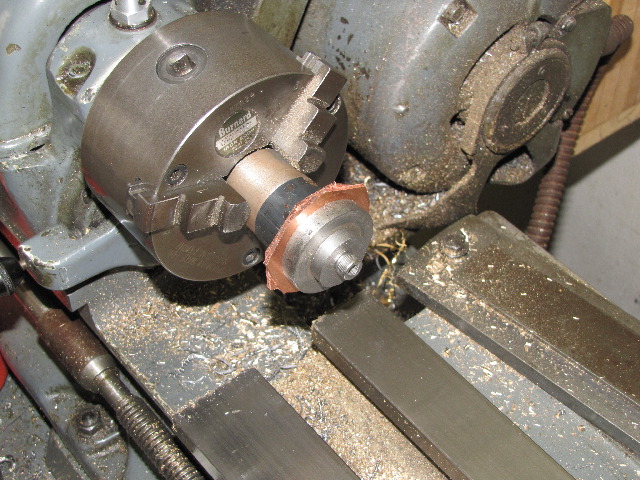
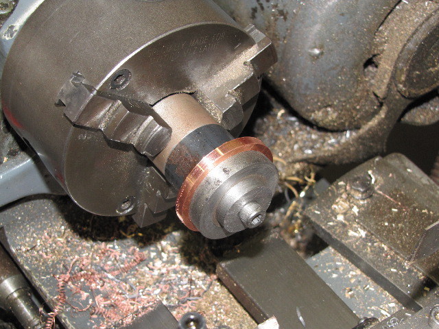
I drilled 6mm holes into the centers of each bit of plate, and screwed them on a rough mandrel using available bits & bobs in the lathe to machine to shape:
s0298.jpg


The copper was all gummy to machine dry, even though I sharpened up the cutting bit pretty well for the job. So I tried a couple of drops of my favourite cutting/drilling/reaming fluid for each pass; that helped a LOT and made the chips come off nicely, with a decent finish:
s0299.jpg


Then I annealed the discs again, ready for forming:
s0300.jpg


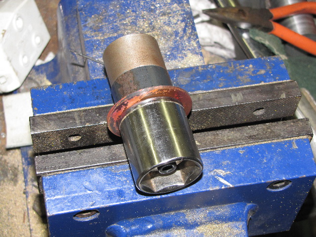
All clamped up for forming; I knew I'd find a use for those cheap sockets I have laying around ;D - this one is the exact size required for the ID of the end cap; saved me the hassle to turn a form tool from good stock!:
s0301.jpg


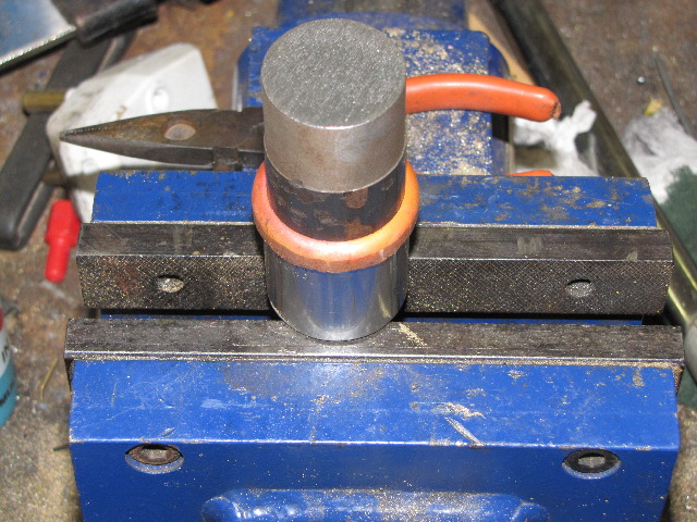
Formed - I used a smallish hammer to get it to around 45 degrees formed on the side, then used a 4lb (sorry ~ 2kg!) hammer to just bash it down while revolving the lot the whole time. I thought I'd have to stop and anneal the cap again, but didn't need to.
s0302.jpg


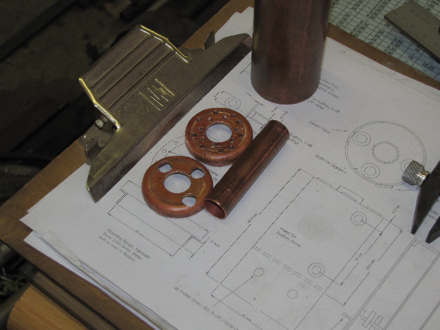
Same process followed for the other end cap. I then drilled the center holes out to 13mm on the drill press and drilled holes as needed for the hedgehog spikes in the bottom end cap and for the bush mounting holes in the top cap. All the holes came out "triangular" instead of round - horrible stuff to drill - even with cutting fluid. To get the 8mm holes for the flanges to shape (i.e. round), I just used a hand reamer. I don't have a 15mm drill or reamer, so just chucked the end caps and bored the center holes to size:
s0303.jpg


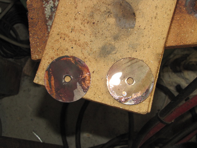
End caps done; can anybody spot the "deliberate" mistake ? :
s0304.jpg

While drilling the holes for the hedgehog pins, I drilled one in the wrong place :Doh:... resulting in uneven distribution. I'll just call it a "Design Feature" for now ::)

Then I turned up and threaded the required bushes from phosphor bronze (what a pleasure after working with the copper!) and was basically ready to clean everything and start soldering together.

There was something wrong though; that "funny" feeling in my tummy was telling me to hold up a bit. So I sat, thought, went through the plans, thought a bit more, and remembered Rich's (Firebird) boiler build -Thanks Rich!. I forgot about the alignment for the water level gauge. (And while typing this up, and having re-read Rich's build part way to get the link, I also realize I didn't leave the parts in the pickle for tomorrow!)

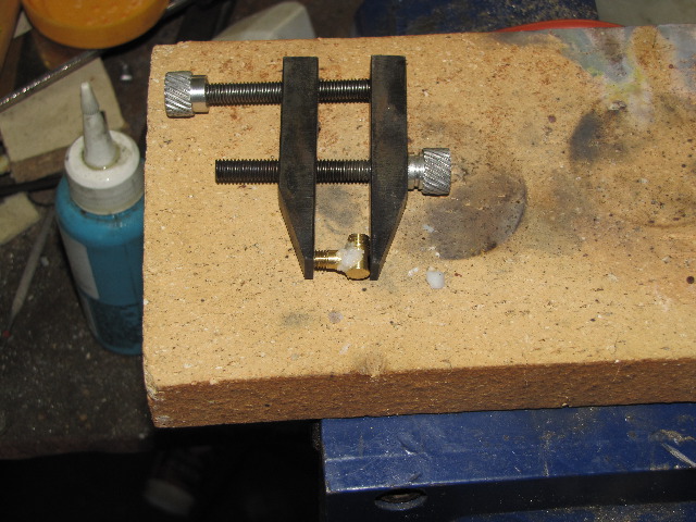
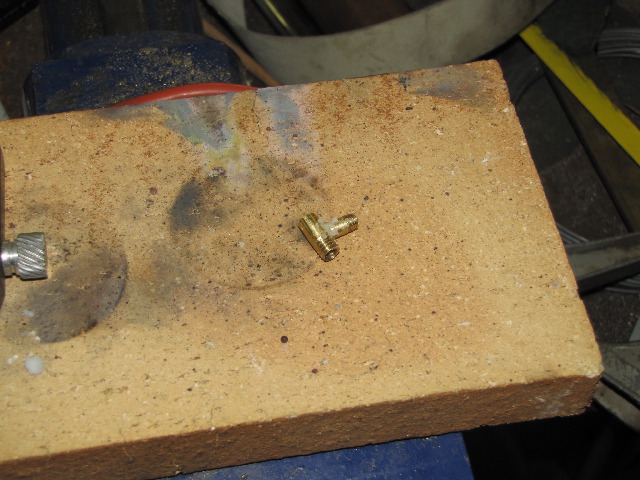
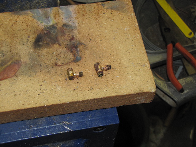
So I started on the bits & pieces for the guage glass; simple turning & threading of bits of brass rod - I'm really glad I made those tailstock die holders!, though I wish I had invested in M5 and M6 Fine taps and dies as well; would be much better suited to this purpose. Next two photos shows the parts fluxed up (maybe too much!) and ready to be silver soldered:
s0309.jpg

s0310.jpg


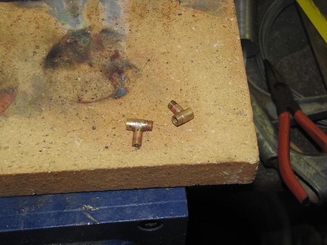
All soldered up; still too much solder applied though! :
s0311.jpg


After about 30 minutes pickle in some citric acid:
s0312.jpg


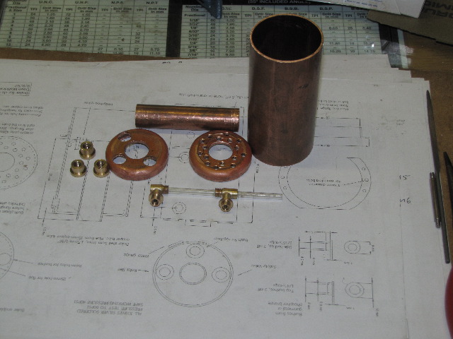
The net results of today's work on Fred:
s0313.jpg


Regards, Arnold
 
Not bad for a day's work, Arnold! I wish I could achieve that much in a day ;D

Keep those pictures coming! I'm enjoying the ride ;D

Gordon
 
Back
Top