Building Fred

Home Model Engine Machinist Forum

Help Support Home Model Engine Machinist Forum:

This site may earn a commission from merchant affiliate links, including eBay, Amazon, and others.
Thanks for checking in everyone :D

Jim (M) - I'll take some photos of the adapter ring & post for you tomorrow evening
Zee, thanks ;D - No pressure to finish it then :big:
Dean, oh yes - million times better; I hate fruitcake ;D
Jim (BC1) - you should hold those little plates on your own finger to appreciate them - Rob did a stunning job!
Ariz - thank you. No I don't own a mill yet. Fortunately, the old Myford is a very versatile machine. If things go to plan though, I'll have a mill by May next year.

I should have some more progress to post on the loco tomorrow evening as well, as its a public holiday here in Namibia tomorrow ;D

Regards, Arnold
 
Some more progress on Fred today ;D - I love public holidays!

First up, JimM, as requested - some shots of the drill spindle adapter - the top ring of grub screws tightens up on the drill spindle, and the bottom ring on the reduced diameter just below where the morse taper ends and the jacobs taper for the chuck starts. Remember, I put the chuck on the jacobs taper using heat. I should really put shorter grub screws in the section that connects to the spindle... :
s0202.jpg

s0211.jpg

s0212.jpg


On to Fred...
Started off with marking out the port block:
s0195.jpg


Dave says to cross drill the port holes first, then stick brass pins in the holes, then drill the passages in the block - the brass pins are to prevent deflection/bite-in when the passages reaches the port holes. I did it the other way around; I don't have suitable brass pins, but I do have a lot of 2mm bronze brazing rod. This is tougher than brass, so could still cause deflection on the deep passage holes, so I drilled the passage holes first, and then the port holes. Some deep drilling on the lathe - my cheep 'n cheerful drill press is not accurate enough... :
s0196.jpg

s0197.jpg


Next up the port holes & pivot hole - for this the drill press is good enough, as these holes are not so deep. Notice the brazing rod pieces sticking out of the passage holes:
s0199.jpg


Bottom section of port block done; notice the half-drilled notches in the pins where the ports meet up (the one on one end just barely :-[) I wasn't overly concerned about getting the pins out after drilling, as the brazing rod is pretty tough - they came out with a couple of to-and-fro wiggles with a pair of pliers to loosen them:
s0200.jpg


Next up, flattened the cylinder faces on some 1200 grit W&D on a glass plate (the tapping chart is below the glass plate):
s0201.jpg


The top part of the port block was just turned to size in the lathe & parted off. Then marked out for the inlet & exhaust ports as well as the "through" ports that meet up with the reversing valve. - Drilling the ports:
s0205.jpg


After that, I started on the threaded steam inlet on the side, and promptly made a mess-up of that by over-threading and thus stripping out the threads. Fortunately the exhaust side was not done yet, so I switched around and re-did it - successfully this time. The exhaust needs (in my case) a 3.3mm hole, so I turned, drilled & soldered a brass bush in the misthreaded side for the exhaust - see red circle in picture. It came out OK, so next up, I used a 2mm center drill to "stretch" the passage connections (they don't align up - according to the plans); Dave mentions filing some fillets to do this, but the needle files I have is a bunch of junk, so I used the center drill; crude yes, but effective. Also, there are some machining grooves left from parting off - I left them, as in my opinion they would help wick the solder through and isolate the ports when soldering. The other face is as smooth and flat as I can get it.
s0206e.jpg


Next up, I turned & threaded the stud that works to keep the reversing valve seated, screwed it into the block, and put the top of the block on; the stud helps with alignment of the top part of the block to the bottom. As the stud was in place, i used some spacers and basically locked the top part of the port block to the bottom; then clamped the whole lot by the spacers in the vice, and soldered it together:
s0207.jpg


Final result after getting rid of excess solder - some tricky finger-manipulation to close and open holes, and blowing by mouth into the port block makes me think that everything that must be sealed is, and that the passages were not blocked by solder.:
s0208.jpg

s0209.jpg


So that's progress on Fred until the weekend :)

In case some of you were wondering what the story is with the bunches of small drills lying around... I recently spent a bit of money on several each of the different small sizes, but they are all in one plastic bag currently, so I had to sort them around to get what I needed. Earlier this week, I caught our accountants emptying a safe & chucking boxes full of old 3 1/4" floppy disks in the garbage. First off, they got a firm reprimand from me about just chucking "data" in the trash (I'm responsible for IT security ::)) - so they promptly handed the whole lot to me to dispose of "responsibly". My young assistant was in a foul mood and grumbling about wanting to break something, so I gave him the floppies, which he happily destroyed (picture a young lad jumping up and down on a pile of disks - then with a pair of scissors and a vengeful grin - you got it ;D)
I kept the containers; nobody wants them as floppy disks are now brothers of the dodo. Tomorrow I'll go and "rob" my bank of a roll of the free zip-log bags they give out for coins - these bags fits nicely in the old floppy containers, and I can get the small drills et al sorted :big: :
s0191.jpg


Regards, Arnold
 
Nice one Arnold Thm:

Great thread :bow: :bow: :bow:


Regards Rob

 
Thanks Arnold, I'll be knocking one of those locking rings up at the weekend - it even looks simple enogh to be within my skill range :)

Cheers

Jim
 
Great work thus far Arnold! Fred is going to be a grand old man some day!
 
It's coming along well, Arnold. I'll be glad when the weekend gets here, so we can see more of your build.

Dean
 
Progessing well Arnold :bow: enjoying the thread

Have fun

Stew
 
Rob, Jim, Mike, Zee, Dean & Stew - Thank you for checking in and your kind responses :)

Jim, go ahead & make it - there is nothing like practice to build confidence, and, while the adapter is simple to make and need not be all that precise, I'm sure you will learn from the process :) - and don't put yourself or your skills down - we ALL had to start somewhere, and continue learning as we go along. Just work at it and take what I'll call the "Zee Test" once in a while and compare your current skills with what you did 6 months ago, and you will be surprised :) (Thanks Zee; it works for me!)

Some more work on Fred's bits & bobs....

First up, cut a piece of brass flat bar and marked out the top section of the reversing spool valve:
s0218.jpg


Hacksawing to rough shape - a lot of filing followed, but I did not take a photo of the end result:
s0219.jpg


Some brass turned to diameter & laid out for the bottom section of the spool valve. I used a 1mm center drill to just dimple the front of the stock to get the center point, then compasses to mark out the radius. A light scribe with the cutting tool tip (has to be dead on center) by cranking the cross slide marks the first cross line, then, taking advantage of the myford's flat ways and a square, rotate the chuck with the line vertically square and mark again with the cross slide:
s0222.jpg


Then drill the 2mm center hole, and part off using the shank of a broken 1.6mm drill bit in the tail stock to catch the workpiece:
s0224.jpg


Made a little jig for the drill press; just some offcut mild steel slightly wider than my toolmaker's clamp; drilled a 2mm hole part-way through it & stuck a bit of 2mm brazing rod in the hole & clamped in the drill vice. The spool bottom's center goes over the pin, and I clamp it with the toolmaker's clamp. A 2mm center drill is put to use to drill curve approximations in the workpiece:
s0228.jpg


In use:
s0229.jpg


And done; a little filing required still... at the top of the photo is a partial piece of the top of the valve after filing that I forgot to photograph earlier:
s0230.jpg


Next up, I turned the end of a bit of ~5mm aluminium down to 2mm for a tight fit for the spool valve's top and bottom parts. This is for alignment while soldering them together, without getting everything stuck too much to the pin. A trial check before soldering:
s0232.jpg


Some 0.5mm solder rings & pieces put on the top part - if you look carefully, you might also see 6 light punch marks around the perimeter to keep "just" a little clearance for the solder to flow between the 2 parts:
s0233e.jpg


Other part was put back on top, and I just heated the whole lot with a butane torch. When the solder started flowing, I pressed the parts together with a heavy piece of mild steel placed on top, and let the lot cool. End result (too much solder :-[ ):
s0237.jpg

I then spent some time with a scribe & drilling bits in a hand-held chuck to clean out the excess solder manually.

Next up, it was on to the big ends. Some brass bar - long enough to make both big ends centered in the 4-jaw and turned down on one side; I then drilled & tapped the end M3 for the 3mm stainless steel connecting rod.
s0238.jpg


Lazy rotter that I am, I then just fit the collet chuck & reversed the part for doing the other end. This could easily spell disaster, but my cutting tool is nice and sharp, so no problems. Best would have been to use the 4-jaw again and just spend the time to center everything... :
s0239.jpg


Next up was drilling 1.4mm holes for threading for the big end bolts. The myford's a bit slow for drilling these holes, and the pedestal drill, while capable of reaching the speed needed, just not accurate enough. What to do? I have drilled a couple of thousand of holes in PCBs with my Dremel and it's small press; not entirely accurate either, but might just do the job. So I mounted the parts in the myford's milling vice and gave things a go with the Dremel in it's stand:
s0240e.jpg

Worked a charm :)

Today was a real sizzler here; at 15:00 it was 36 deg C in the shade - got a shot of Zorro the swarf magnet trying to cool down a bit :) - just checking if anybody reading this is still following :big: :
s0241.jpg


I used a slitting saw to slice off the end caps of the big ends; much less work than trying to saw & file to size:
s0242.jpg

I had to spend a couple of minutes searching for the first one slit off through the swarf behind the lathe :-[... - the second one was prevented getting flung away by stopping _just_ short of it coming off, manually breaking it off & filing away the left-overs.

Rob (Thanks Mate!!! :bow:) sent me some 10BA taps. These are worth more than gold to me, so I first (crudely, but effectively) made a tapping guide and tap holder to tap the big ends from HRS I have lying around. Clamped the workpieces in the Myford's milling vice and went for it, with very nice results. First photo shows the setup, guide & holder. Next is a close-up of the result:
s0244.jpg

s0243e.jpg


Finally, the results of today's work... Not much to show, but most satisfying :)
s0246e.jpg


Regards, Arnold
 
Looks great!!! My pouches aren't allowed in the shop:eek:(
 
Hi Arnold

Great job :bow: :bow: :bow: :bow: i like the way you made the reversing valve Thm:

Regards Rob
 
The 'Zee Test' eh? Cool.

I thought the use of the machinist clamp was interesting. I made one early this year when I was starting out. I've never used it and have wondered on more than one occasion how I would. I appreciate the idea.

The 'reversing spool valve'...why did you make it as two pieces and solder it together?
 
Arnold, yet another splendid display of metal working. :bow: Very nicely done indeed. I can appreciate the method of which you produced that valve, ingenious it is now.

BC1
Jim
 
Looking good, Arnold. Keep it coming!
Dennis
 
Another good day in the shop, Arnold, and it looks like you're having some fun.
The punch marks in the valve.. never thought of that. Everyone has a trick to
share here. When I saw all that solder though, uh-oh. It looked like quite a bit!
I'm glad you were able to manage the clean up in those little slots.

Thanks for the snap of your pooch. I have one about that size. She's the reason
I vacuum the shop floor every day. My shop is in the spare bedroom, and she
wanders around at night.

Thanks for keeping us up to speed on this neat loco.
Full steam ahead!

Dean
 
Thank you for checking in guys :)

Zee, I could have made the valve as one part, but it is fiddly for me, as I have to set up the lathe for milling, and then have to battle with the dividing head and a lack of rigidity on my setup. I don't have a rotary table; If I had one, I would most likely have made it as one part.

Everyone else who commented on the valve construction - thank you, but I cannot take the credit for thinking of doing it this way; the original plans actually shows this method for making it :)

Dean, as to the punch marks, quite a few HMEM members have made reference to the method in their posts in the past; so I'm just using a trick learned from the forum as well :). The pooch is quite good in the shop; doesn't even complain about getting swarf brushed out. He's just one of three I have; the other dog is good in the shop too, but the ***** is banned; she steals tools and hides it out in the yard - that is if it can't be chewed up.

On to Fred; didn't do a lot today; just finished the top cylinder covers and the 2 pistons:
s0253.jpg


Regards, Arnold
 
Hi Arnold,
Completely off topic, but what breed is you pictured dog?
Regards,
Gerald.
 
Hi Gerald - don't mind OT :)
He's a salt & pepper miniature schnauzer.
Regards, Arnold
 
Some more progress; I wanted to have the loco running on air by tonight, but a tool for tightening hexagonal fasteners was carelessly projected into the mechanical processing plant...

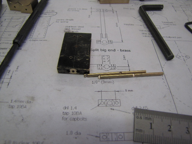
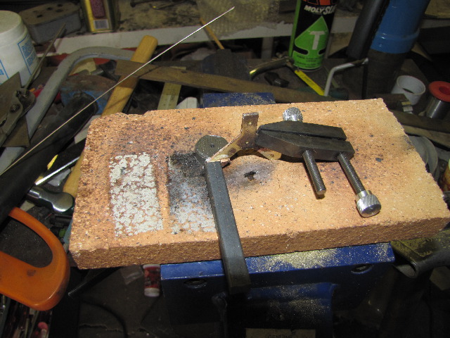
On Thursday evening I made the 2 con rods from stainless steel - threading one end (to get rid of the last bit that wasn't threaded properly, I just used the edge of a small half-round file to make the undercut after doing this thread):
s0257.jpg


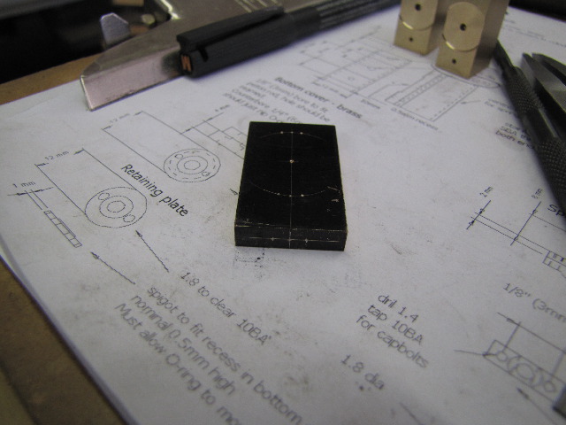
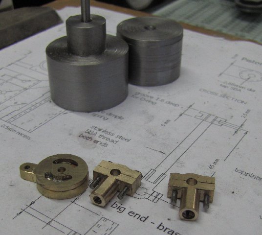
Saturday I made the bottom cylinder heads. Here I deviated significantly from the original plans. The originals show a simpler solution, but would be more difficult to disassemble for maintenance later on. I opted for cylinder heads that could bolt on - after checking that adequate clearance was available for these, and traditional stuffing glands. Digging around available stock, I decided to make each head out of 2 parts to minimise stock wastage

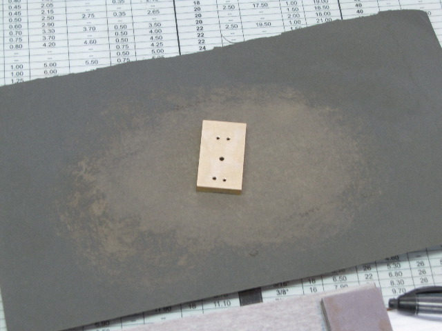
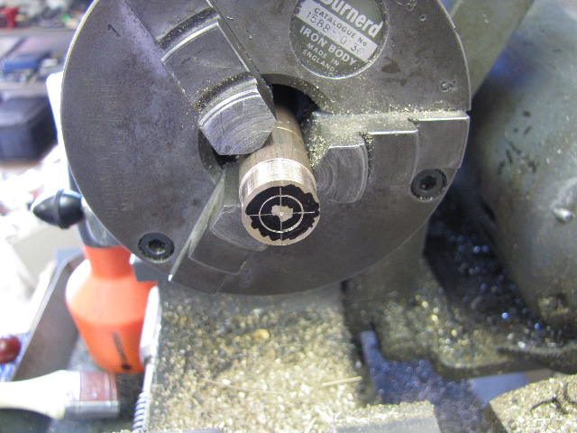
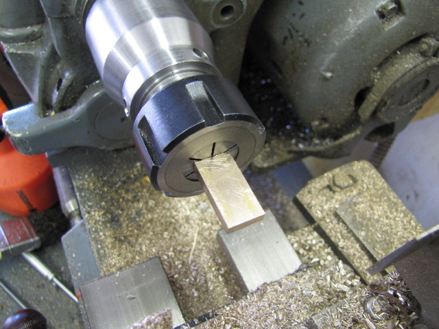
First up, machine the "inside" face of one, with a register to accurately locate on the cylinder head:
s0260.jpg


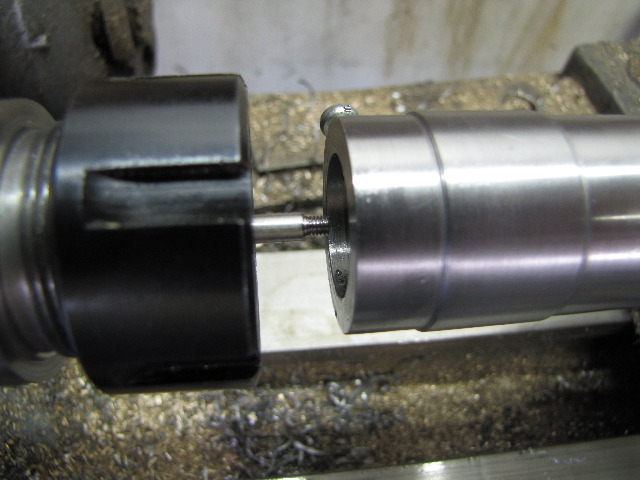
Grabbed the register part in the collet chuck after both were done in the 4-jaw, and faced to thickness with light cuts; there's not a lot getting held in the chuck! :
s0261.jpg


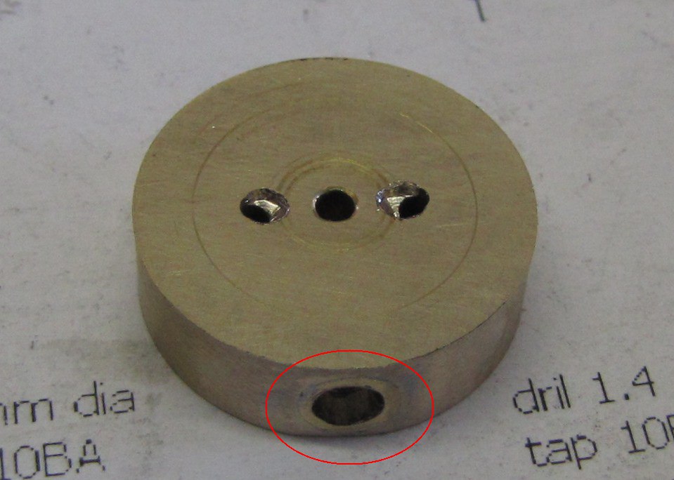
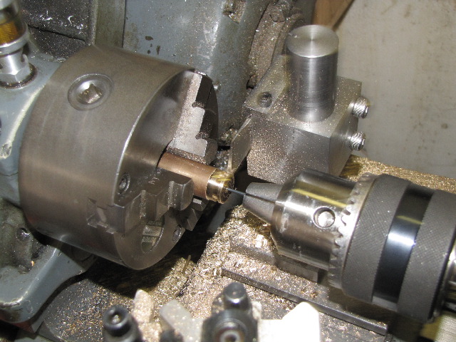
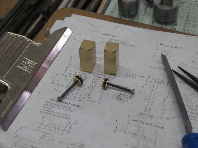
A bit of a lapse in photos followed; I drilled & reamed the some brass threaded rod I have to 4mm for the inside of the stuffing glands. Then drilled part-way to 5mm & threaded to M6. A "modified" m6 cap screw was used to cut the thread to final depth, as I don't have an M6 plug tap. The outside of the rod was then turned to a tight fit for the 8mm holes I made in the cylinder heads earlier. Parted off, pressed into the cylinder head, and repeated for the other one.

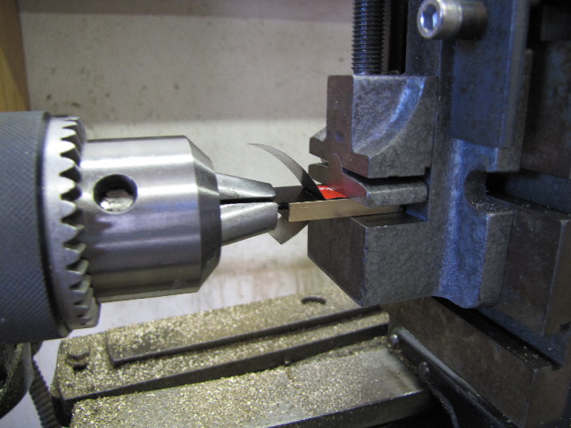
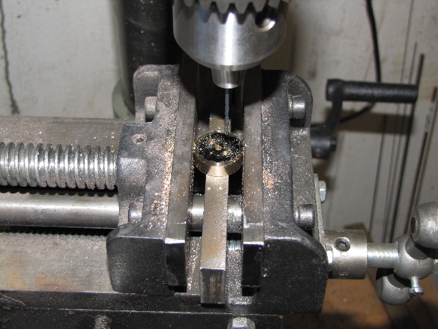
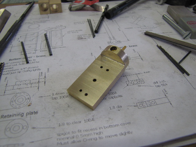
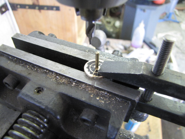
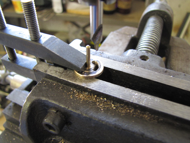
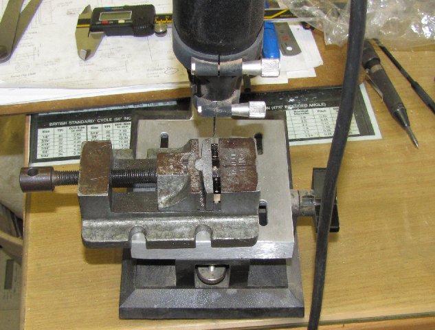
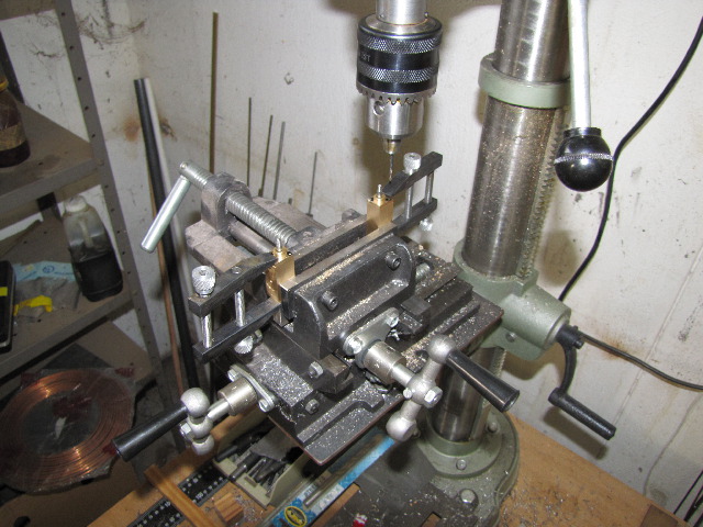
I decided to go the studs 'n nuts route to bolt the heads to the cylinders; the studs to be loctited into the cylinder, so instead of faffing around with a 1.4mm tapping drill for the 10BA studs, I went with 1.5mm; my drill press chuck can clamp 1.5, but not 1.4. Toolmakers' clamps keep the cylinder heads in place while drilling:
s0262.jpg


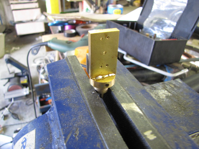
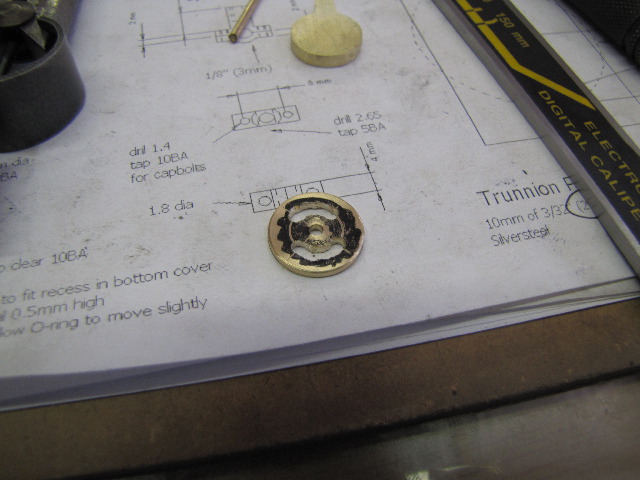
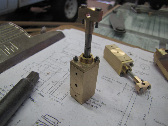
All bolted up; the side of the cylinder head on the port face side is intentionally shorter; I don't want it running against the port block.
s0267.jpg


I wanted to carry on past this on Saturday, but social life made a call & off to a BBQ I went; that's also why I didn't update last night...

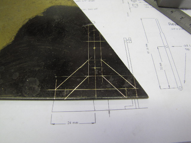
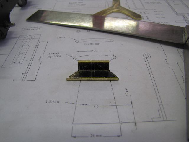
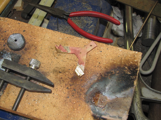
This morning, after recovering from a very late night out, I started on the engine mounting. 2 weeks ago, I found some brass plate offcuts at the place I get stainless steel from; I put a corner of a triangular piece of 2mm plate to use:
s0268.jpg


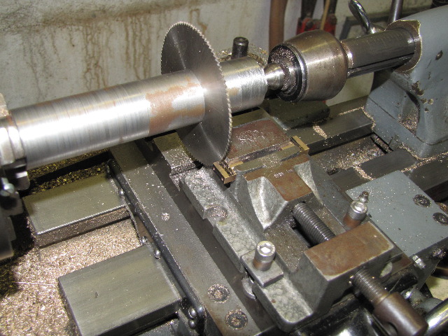
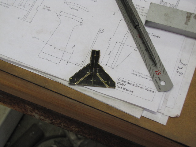
After some free-hand bandsawing:
s0269.jpg


And some time & sweat with a file:
s0270.jpg


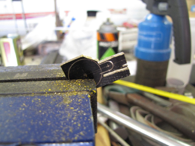
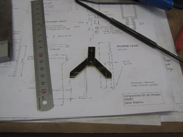
This piece of plate was nice and soft, so I marked out the mounting feet on a flat piece, and used a hammer and the big vice to make it into an angle:
s0271.jpg


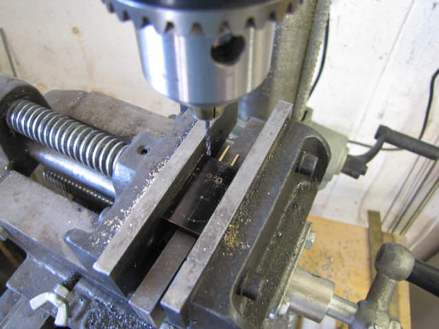
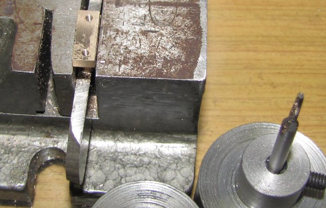
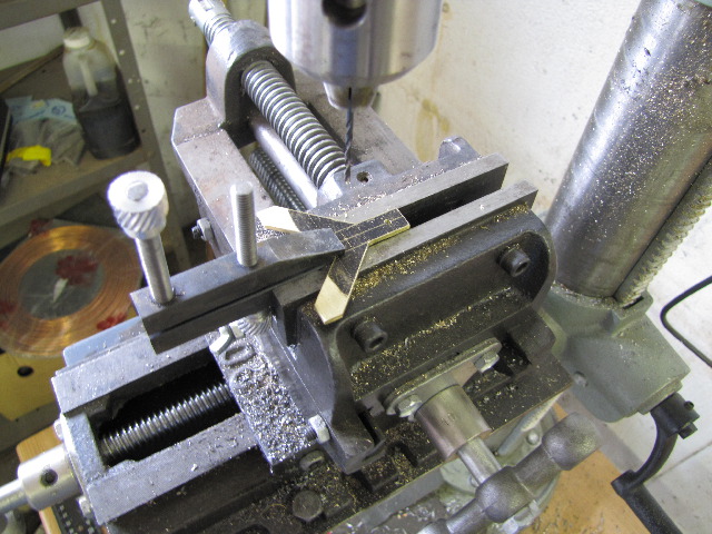
Once again using the toolmakers clamp for drilling an awkward-to-hold piece:
s0274.jpg


Now comes a bit of a booboo...
Having made the engine mounting & it's feet, they needed to get soldered together. No soft solder for this one, silver solder is needed for a high-strength joint.
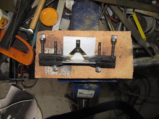
With the back edges of the feet a bit round from bending and difficult to keep square, I decided to use a piece of aluminium angle to keep everything together and nice and square, and to let the silver solder flow onto the "round" part to make the mounting nice and flat. It looked so good all set up and fluxed, ready for soldering:
s0276.jpg


Used my oxy-butane kit to heat up one side; flux bubbled, flowed & I needed "just" a bit more heat for the solder.... then the ally called it quits:
s0277.jpg

Sorry; poor photo; I was just a tad annoyed. Might have worked with thicker aluminium, might not...

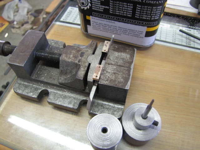
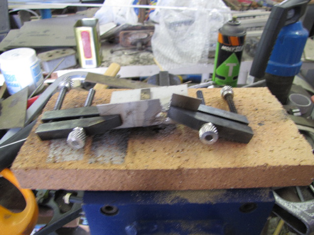
So I left everything, including myself, to cool down, cleaned the parts up again, and used bits & bobs to hold things in place and re-did the job:
s0278.jpg


Dumped the mounting in citric acid for 1/2 hour - came out OK; I overdid the silver solder on the one foot, as it moved while doing it. I'll clean the excess off later and neaten up the mounting:
s0279.jpg


Next up, marked out the mounting holes on the loco frame for the engine mounting; lots of calculations needed off different sheets of the plans to get correct measurements, but finally got it. Used a square to make sure things stay in alignment, and the 2mm drill bit finger-twirled through the mounting holes to mark the spots through the paint.
s0280.jpg


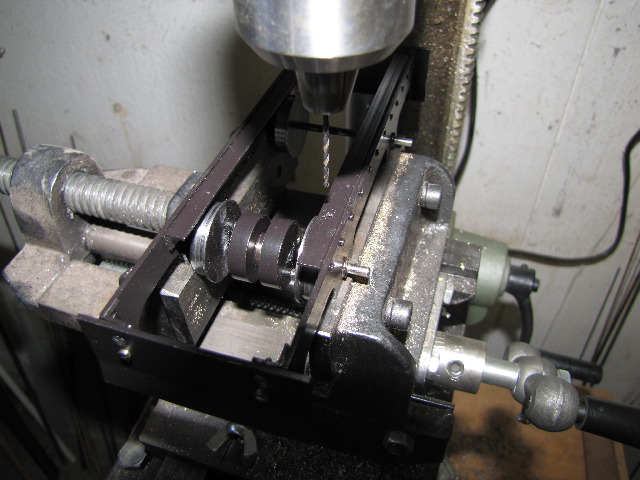
Drilling 1.6mm holes for M2 tapping on the marks after punching. I supported the frame on the vice jaws, and held on firmly. Drill press set to 1500 rpm, and a good positive feed used, as I don't want a repeat of the stainless angle work-hardening like I had earlier in the project:
s0281.jpg


The tapping guide I made for the 10BA taps works well for the 2mm taps as well, so just tapped the holes after drilling; using all three taps in sequence.

Next up, I calculated & measured the correct end of the port block for drilling & tapping the mounting holes. I stuck some masking tape on the port faces to protect them in the vice while drilling the holes; with the drill press depth stop set so I would not break into the steam passages on the inside. Tapped these holes as well, and to get to depth, I ground the tip with the broken teeth off the 3rd tap in my old M2 set, and used it to thread to bottom on the holes :) - never throw away "abused" taps! - Sorry no photos again...

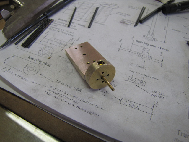
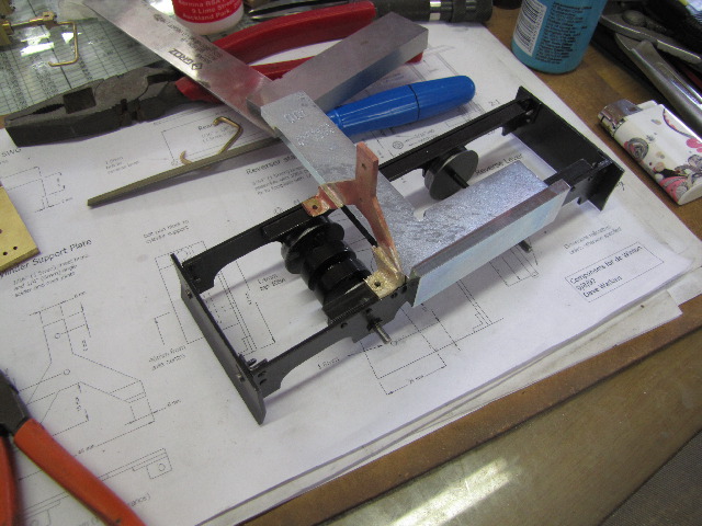
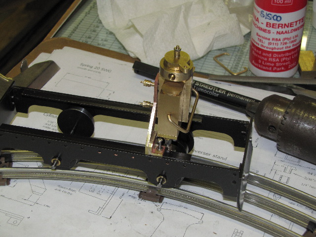
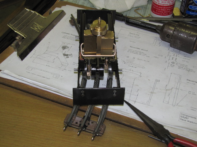
Mounted everything up for a look-see & to see where problems might (DID) arise. Lots of screws to shorten/make, and parts to give a final finish to still left here, but tests first:
s0282.jpg

s0284.jpg


Now the problems started...
When turning the engine over by the wheels, it was still very stiff; I felt the pistons were stiff in the cylinders earlier; primarily because of the o rings, and I hope that will wear in properly. Couldn't go full-throw to the bottom of the cylinder stroke; checking, I found that I must have made a mistake somewhere, and that the port block is mounted about 1.5mm too high. Top of the cylinder stroke with the big ends disconnected has adequate clearance, so I'll make new con rods, 1.5 mm longer; easier than to re-do all the mounting holes!.

And then the real spanner in the works hit... After dismantling the engine, I just gave the main drive wheels a spin, and they were stiff and wobbled! - never did that; was running very smooth up till now. Closer inspection, and the loctite had come loose on the crank pins, and the assembly warped. So, I need to disassemble the crank assembly and drive wheels and re-do it. This time, I'll silver solder it. Oh well, more practice :)

Regards, Arnold
 
Hi Arnold

Fred is coming along great :bow: :bow: :bow: :bow: :bow: :bow:

Regards Rob
 
Back
Top