Building a twin cylinder inline i.c. engine.

Home Model Engine Machinist Forum

Help Support Home Model Engine Machinist Forum:

This site may earn a commission from merchant affiliate links, including eBay, Amazon, and others.
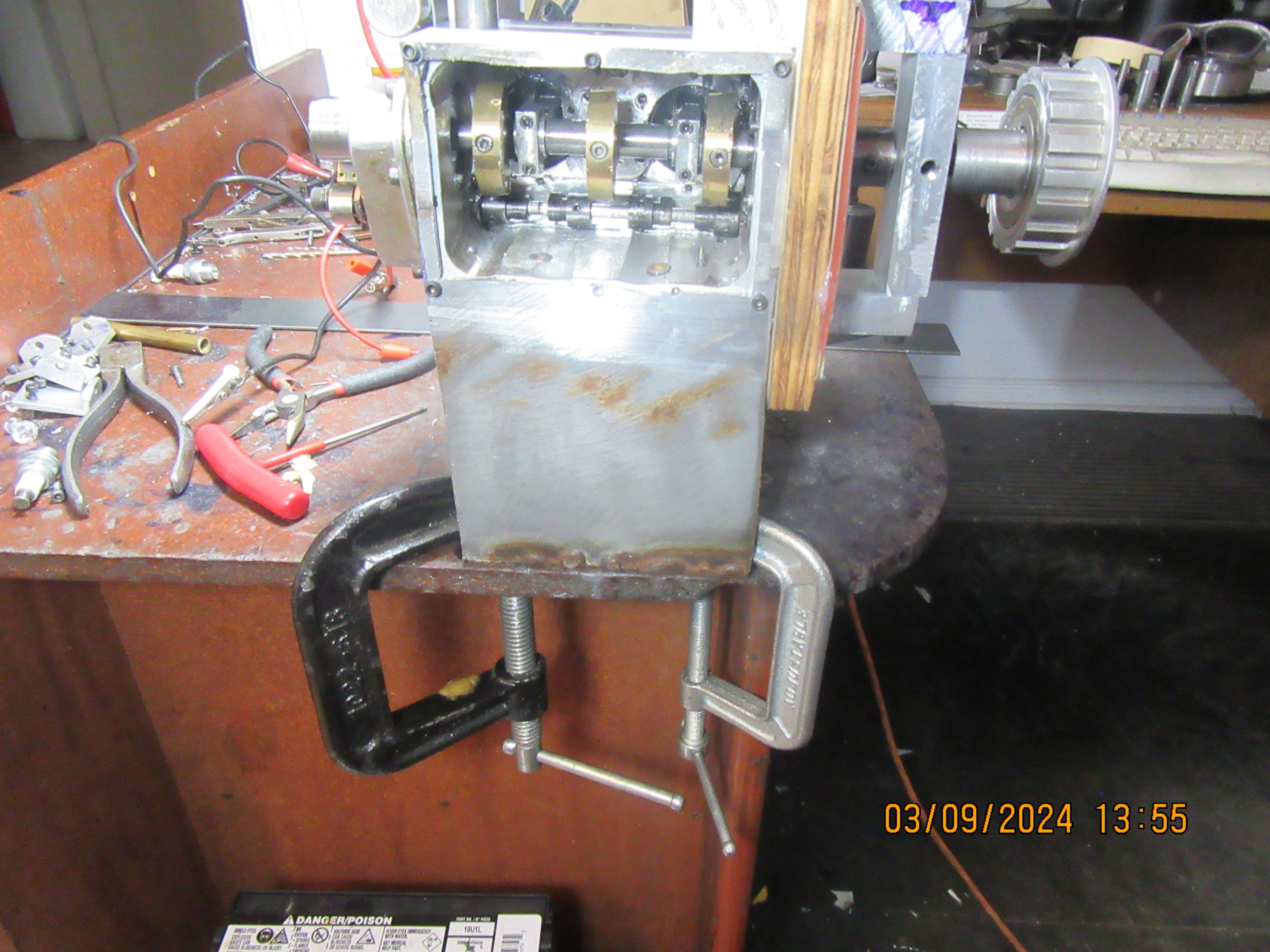
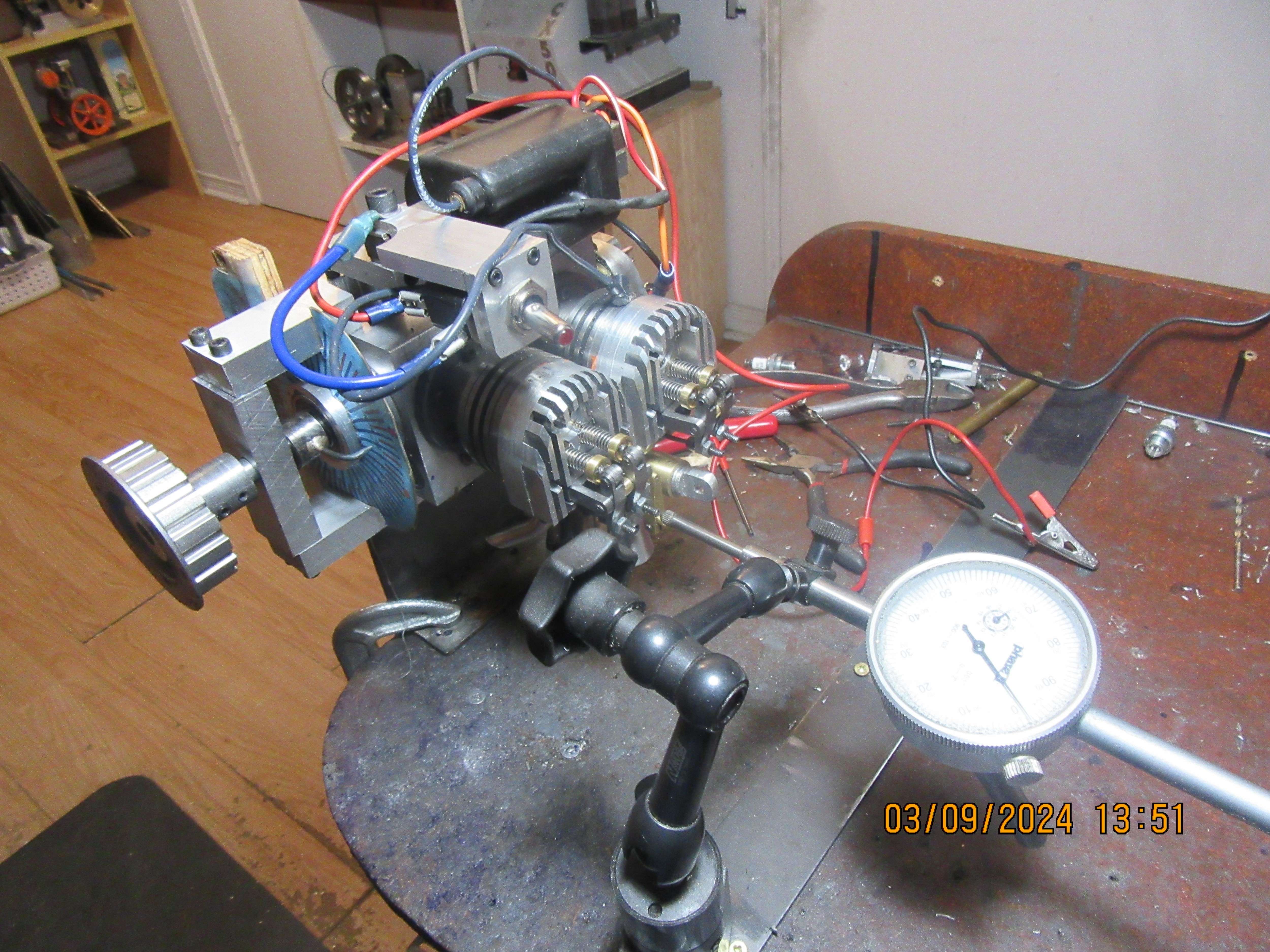
The old cams which were made with a flank radius are out!!!. The new cams with no flank radius are in. What a nasty, nasty job it has been. All of the rocker arms are rocking their little brains out when I turn the crankshaft. Now, once again I am ready to set my valve lash and cam timing. Setting the valve lash is not really a big deal. Setting the cam timing is. I haven't got there in my head yet, but I need to figure out a set up where I can put a dial indicator on the rocker arm to tell when it begins to be influenced by the cam, and yet still have access to the underside of the engine to spin the individual cam segments until they begin to influence specific tappets. This is where life would be a lot simpler with a one piece camshaft with lobes on it. I THINK that I have to mount the engine so that the cylinders are horizontal, which allows me access to the rocker arm side for my dial indicator but also gives me access to the inside of the crankcase to adjust the individual cam segments. I'm going to stop, have a coffee, and figure out just how I'm going to do that.
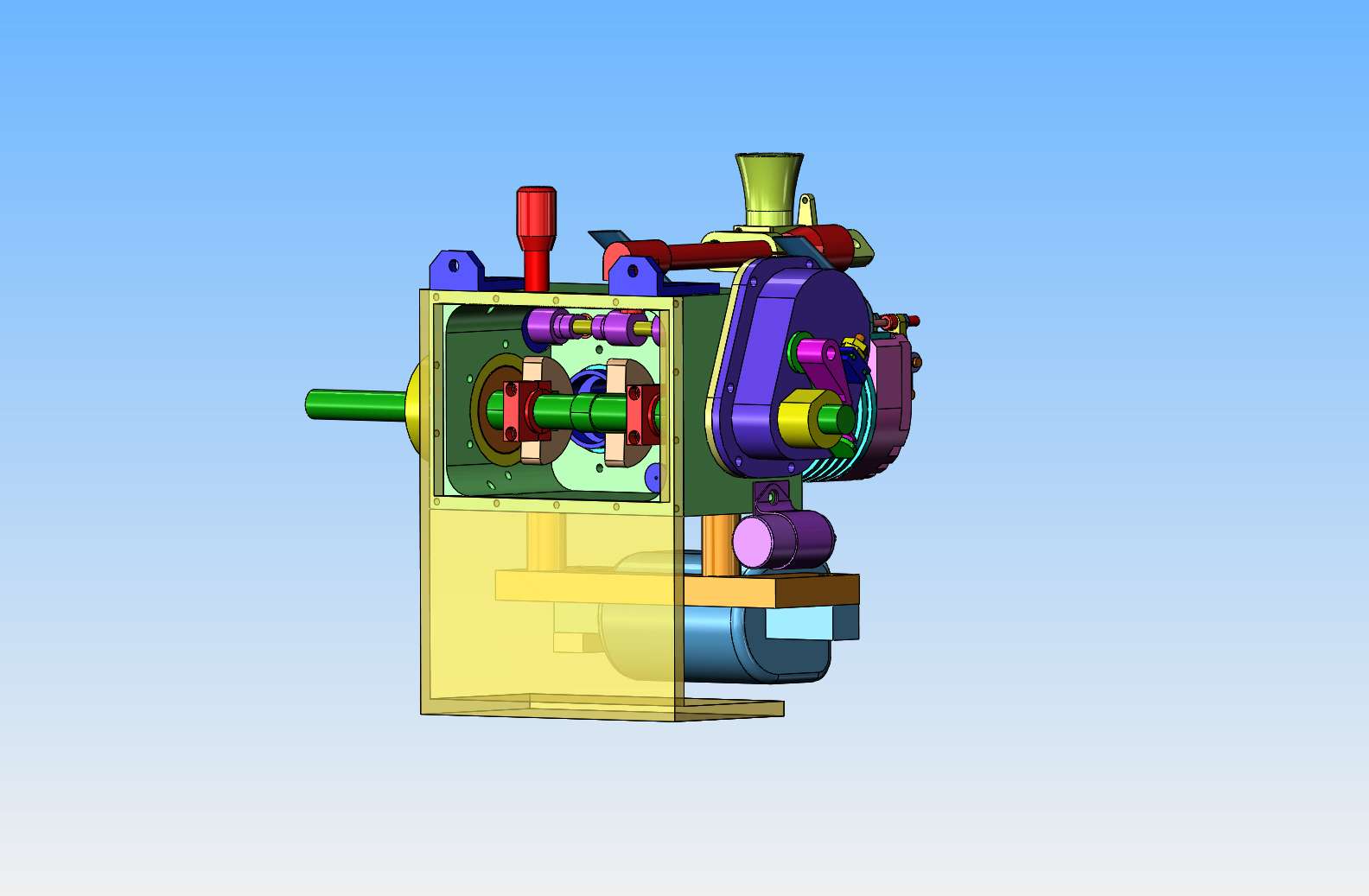
 
I can design an order of magnitude faster than I can build, but I'm going to make a fixture like this. The orange bracket will screw to my tabletop and to the engine, using the sump bolt threads. This gets the engine up on its side so I can get at the individual cam segments. Lots of room on the other side to set up my dial indicator.
a9opQ3.jpg
 
Brian, a suggestion. Make a simple fixture to hold the shaft. Supported just on the ends. Mark the shaft where each of the lobes go and slide them on the shaft. Go on line and search 'protractor ' and print it out. (Degree wheel) Glue it to a piece of card stock and glue it onto the end of the shaft. Give yourself a pointer, registration mark. Now set up a dial indicator (plunger type) lock the first lobe in place, set your indicator so it has .010 travel to zero and line up your pointer to the degree wheel. Now rotate the camshaft to the proper amount of degrees and rotate the second lobe to where it shows zero on the indicator and lock it in place. Repeat. This should be a lot easier than trying to do it in the engine. Whatever you have the indicator mounted to slide it along the base of the fixture to keep the indicator at the same axis reference.
 
George I mentioned this on another forum. You can just hold the shaft in a rotary table and use that to set the cams as per the drawing, Malcom who designed the engine shows it being done in the article and this is me using the same method for another engine. Easy now with the flat flanks

20190921_133055_zpspcdc4gtc.jpg
 
You're right. I just didn't know what equipment Brian had available.
 
Okay!!--In the world of wild and wacky set ups, this may win a prize. First thing I did before any of the set up was to set the valve lash so that there is 0.005" clearance between the rocker arm and the end of the valve stem when the tappet is not up on the cam. Did this once for each valve. Then, as fortune would have it, I found an old fixture that was used many years ago for something else, and it worked great for getting the engine mounted with the cylinders horizontal. This gave me great access to the individual cams. I screwed a strip of mild steel to my desk top and that gave me a good place for my dial indicator with a magnetic base. The degree wheel (blue and red) was attached to the engine block, and the pointer attached to the crankshaft. Now I can turn the crankshaft to however many degrees I want before or after top dead center of the piston (or bottom dead center). That crazy looking fixture which sets just outside the pointer has a set screw in it so that when I turn the crankshaft to some specified number of degrees, I can lock it there.
So---I turn the crankshaft to so many degrees before or after top or bottom dead center, lock it in place, then turn the specific cam I want until I see the dial indicator begin moving. At that point I tighten the set screws in that cam, and then move on to the next cam for a repeat.
z2HWIr.jpg

G1boi2.jpg

tW0dQj.jpg
 
Well---the good news is that although the set-up looks rather unorthodox, it works very well. The bad news is that I have managed to thoroughly confuse myself. It's not a problem to set the valve timing on the first cylinder. For some reason it's much more difficult/confusing to set the valve timing on the second cylinder. I ended up writing little notes to myself about what sequence of events followed the timing of the first cylinder. I'm sure that if I think on it long enough it will all come clear to me. At some point later today or maybe tomorrow I'm sure it will make sense and then I will bolt on the bottom sump cover. I did receive the o-rings to seal the ends of my "see thru" gas tank earlier this week. I am very close to being able to start this engine.
 
Make a note of the degree wheel readings where the first pair are set. Rotate CRANKSHAFT one full turn and set second pair to that same readings.
 
Engine is timed and all is reassembled. Had a slight leak at one end of my see-thru gas tank, but a disassembly of the leaking end and a new o-ring stopped the leak. Engine is firing as it is rotated by my electric starting table but not running on it's own yet. I won't be posting any more now until engine is running.
 
Elvis has not left the building!!! I am currently troubleshooting the engine and waiting for the first run. The intake manifold that fed two cylinders and used a single carburetor did not want to seal against air leaks, so finally I made up two individual intake manifolds and used two Traxxas carburetors. (These Traxxas Pro-15 carburetors work fine on my single cylinder engines with the same 1" bore.) I have things to a point where one cylinder is firing consistently but the other cylinder is not firing. I have went to a larger diameter flywheel and that helps, but doesn't quite do the trick. Today I used my new compression tester to check compression on the cylinder which is firing, and the compression tester is registering zero compression. I will post more as the troubleshooting progresses.---Brian
 
On cylinder #1, when both valves are closed, cylinder is holding 60 psi from air compressor. This is a variation on the old "Blow yer guts out" theory, where I blew into the end of the yellow line by mouth to check the cylinder for air tightness. I have also tested the new compression tester separately with pressure from the air compressor and it does work. This proves to me that the valves are sealing and the piston ring is sealing. Now I have to figure out why the pressure is not registering on my compression gauge.
qJVLGQ.jpg
 
This is a new one on me. The hook up shown above holds 60 psi without leaking down. When I hook up the compression tester and turn the motor over with my electric starting table, it is not moving the needle in the gauge off the pin. The cylinder has a relatively small volume, about 1" dia. x 1" stroke, but even when I roll the motor over several times, it isn't registering any pressure build up on the gauge.
 
You have the line from your compressor disconnected when watching for leaking down, right? Otherwise the regulator is doing exactly what it is intended to do, hold pressure at 60psi regardless of the airflow.

As a test, hold a valve open during your leak down test, does the gauge drop to zero?
 
Does the compression gauge have a working check valve?
Does not appear to be one in his leak down test setup. Possibly there is one (brass) at the cylinder head but if so it is in the wrong location for leak down tests.
 

Latest posts

Back
Top