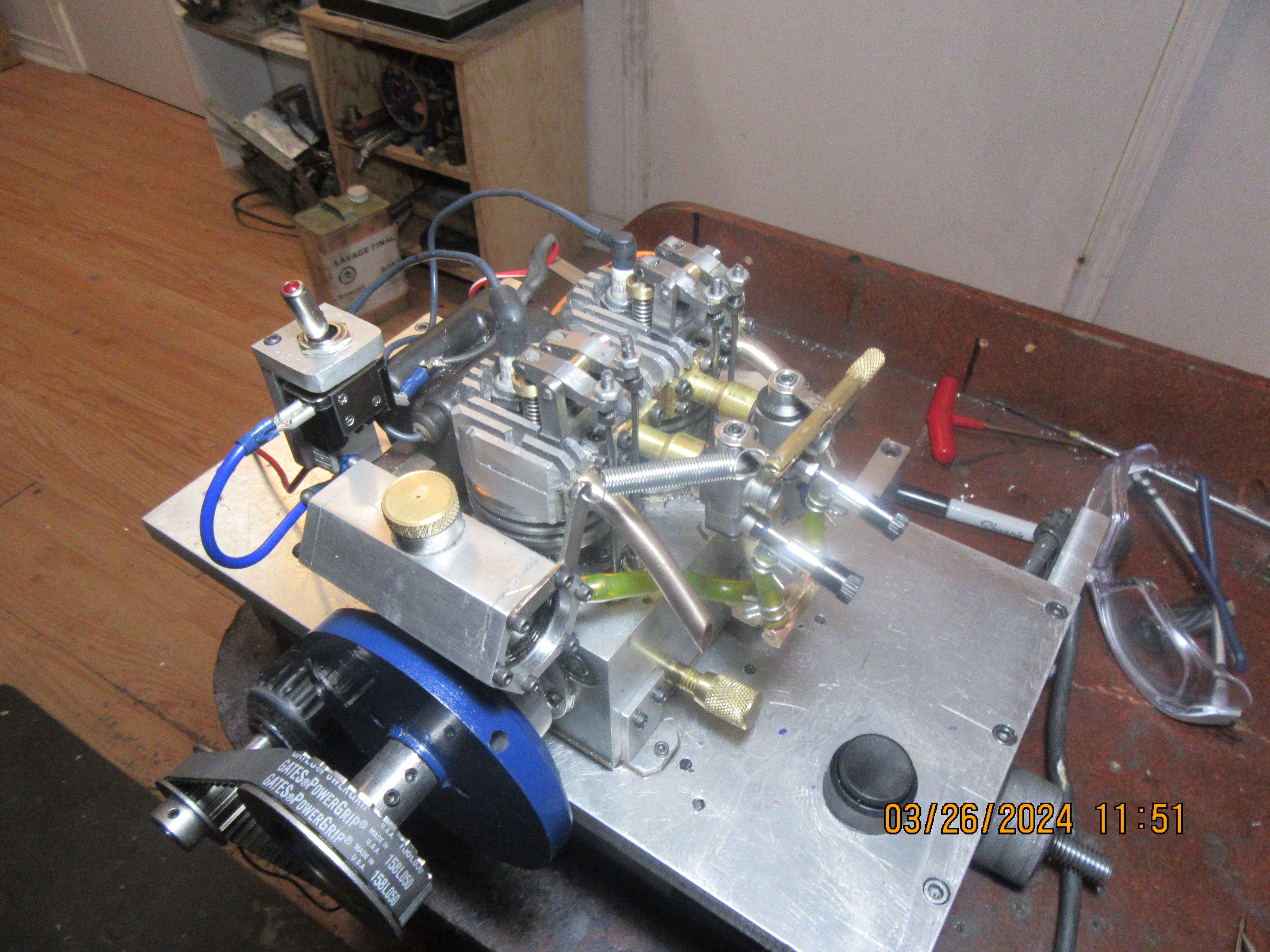
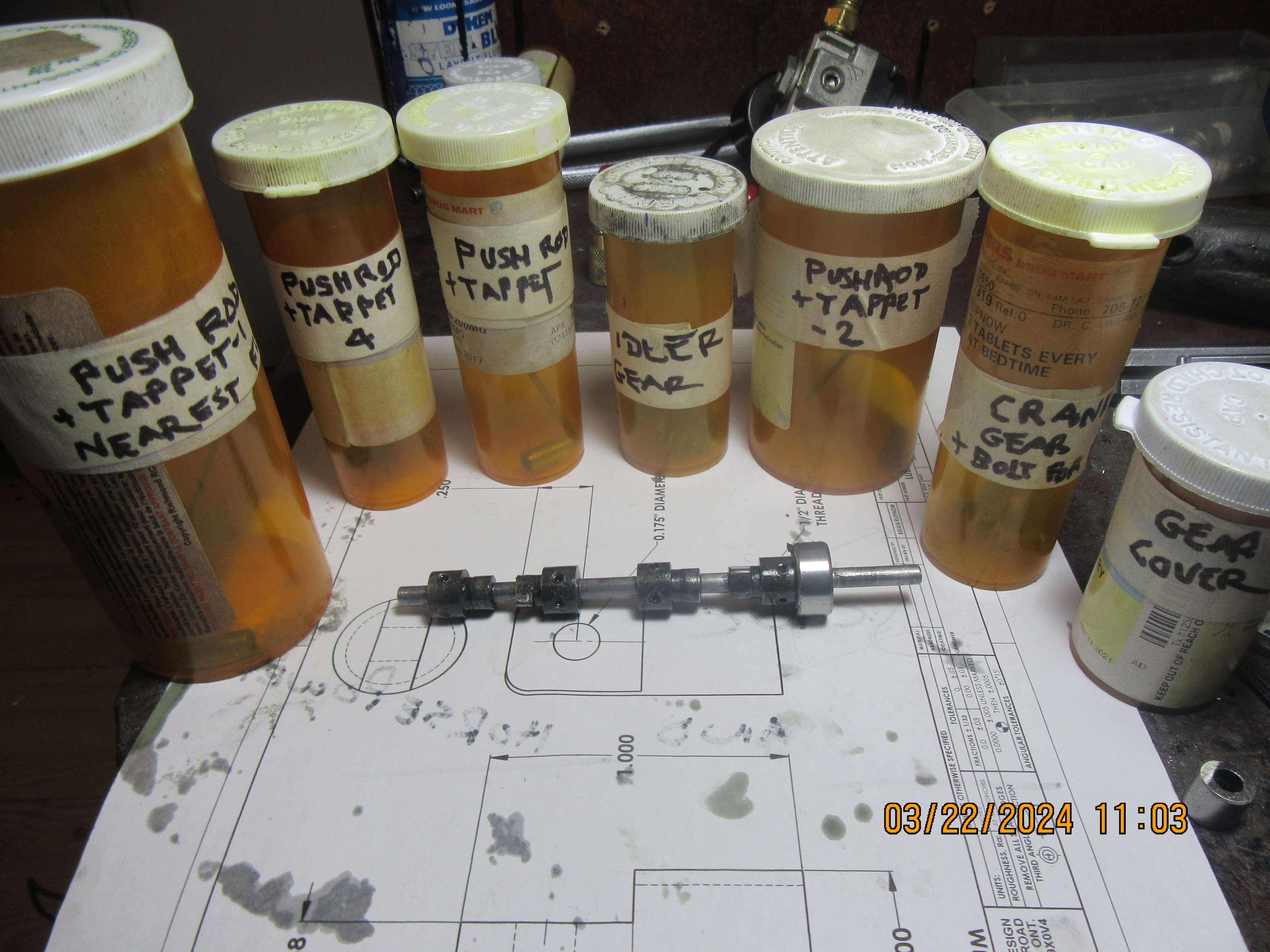
So----The engine is finished. This build has carried me thru January, February, and March. It started out as one carburetor feeding a single manifold that spanned between both cylinders. As the engine evolved, I couldn't get the single manifold spanning between both cylinders to seal properly, so the cylinders were fitted with one carburetor each and a single intake manifold each to get away from the sealing problem. Some confusion on my part lead to having to ask for some help when setting up the individual cams on the camshaft, and I feel that I have indeed learned something new. I never was able to come up with a 12 volt coil that had dual outputs, so I "borrowed" the 12 volt coil of my dual opposed cylinder engine because I know it works. I made a new style of gas tank based on one that Andrew Whale from the U.K. built, with glass ends and I like it very much.---I can now see at a glance if the engine has ran out of fuel or not. Only one problem remains, and that is that I can't get the damned engine to run!! I will continue pecking away at things until I have a runner, and then I will probably post the engine drawings for sale. Although this engine was base on Malcolm Stride's engine, the Jaguar, it has a different bore, different stroke, different ignition and different lubrication system. Thank you all, readers, for following the build.---Brian Rupnow--26-March--2024