Building a 120mm rotary table

Home Model Engine Machinist Forum

Help Support Home Model Engine Machinist Forum:

This site may earn a commission from merchant affiliate links, including eBay, Amazon, and others.
Good heavens man, and you're doing this on the fly? My hat is off to you, that is some fabulous looking work with some equally fabulous results. Well done! Thm:

BC1
Jim
 
Arnold, thanks for letting us look over your shoulder. This has to be one of the most impressive projects I've seen in quite some time.

Best,

BW
 
Arnold,

Or should I say Vern(ier). ;D

Absolutely wonderful, gobsmacking stuff, HATS OFF to you. :bow: :bow: :bow:

Best Regards
Bob
 
Arnold, like the others I cannot tell you how awesome I think your home made R/T is. Magnificent.

I also really like that stamp holder you've made. Good excuse to retire my Chinese stand and relegate it to stamping work down the pike.

:)
 
Sam, Tel, Dean, Zee, Both Bobs and Mike, thank you all very much for your comments - I feel slightly overwhelmed! ;D

Dean, I practiced a bit first on some scraps. Funny thing though; it was easier to get better looking numbers on the cast iron than on the aluminium; maybe because it has a bigger diameter. Oh yes - one letter; one knock! I have one "slightly doubled" 2 from a double knock :-[

Mike, I nearly used the drill stand visible next to the punching setup - but I just couldn't. It's a good quality drill stand and was my only "drill press" for many years, and has an aluminium base, so I don't think it will stand up to hammering. As to the "Chinese" stand you have, I'd be hesitant as well - I'm not entirely sure it will stand hammering on it, but on the other hand, they are so cheap as to be nearly "consumables".

Well, not much to report for today; I spent most of the day getting to my mill's spindle (I finally could after getting those circlip pliers!), disassembling it, cleaning everything thoroughly, and re-assembling and adjusting the bearing pre-tension. No photos of the process though; my hands were too dirty to use the camera :big:.

And boy-oh-boy, what have I been missing out on! Once adjusted and re-assembled, I played around with bits of scrap to see how much of a difference the cleaning and adjustments made, and I was totally surprised! MUCH better cuts, and MUCH improved finishes, even when cranking at a good clip. A difference between night and day.

One of the scraps of HRS I practiced on became the two locking clamps for the RT. After testing the flycutter on some scrap I decided it was worthwhile to jump in and fully flatten and square up the side on which the RT will be used in the vertical position. Standing on edge it was close to, but not fully square, and I ended up using a 0.05mm feeler gauge plate to shim it to clamp it down nice and square. More "no photos", but I took a short video clip while starting a flycut on the surface. If you are prone to seasickness, please do take some Dramamine or ginger first; I was holding the camera in my right hand and cranking the table with my left hand:
http://www.youtube.com/v/UywqSxgYfik

Then I drilled and tapped the top of the base M6 to mount the locking clamps - here is a view of the flycut face and one of the clamps mounted; the other one is on the opposite corner of the table:
normal_IMG_1374.JPG


So, not much to show, but a whole lot gained, for today's bit so I'm confident that I can now start on the T slots in the table for the next step :)

Regards, Arnold
 
You won't have any trouble with the Tee slots Arnold, I cut the ones on the little 3" I made with a crude, home made cutter and they came out just fine.


rotary #1.jpg


rotary #2.jpg


Ditto to what Tel said, Arnold.
I do not find T slots difficult. Mine were cut with a cutter I made from drill rod, and my table is HRS.

Shopmadecutter.jpg


With a factory cutter in CI, you should have no trouble. Just do as someone mentioned, and mill the
"start slot" a little deeper than the T-slots will be.

The fly cut side looks very nice!

Dean

 
Dean, when you guys talk about a "T slot" cutter, are you using a standard "woodruff keyway" cutter or do they make actual t-slot cutters.


Arnold,
I've got to tell you...Have you ever picked up a book and couldn't put it down?

I'm sort of new around here, and I noticed this thread awhile back but never took the time to read it. I finally started reading this around 8pm California time last night but couldn't finish due to needing some sleep. After my 12hr shift today and obligatory wifey time I headed straight back to this thread because I guess my learning curve was still hungry for more.

Thanks so much for the presentation and details.

I have no plans to build a rotary table but the methods and pre-planning you documented will serve many of us for the myriad oddball situations we'll come up against as this hobby unfolds.

So...How do you plan to stop the BP oil well leak? Hope to see that thread soon :bow:

Regards,
Rich
 
putputman said:
Dean, when you guys talk about a "T slot" cutter, are you using a standard "woodruff keyway" cutter or do they make actual t-slot cutters.

As Dean said Arv, they are a purpose made cutter. A true Woodruff cutter won't work 'cos they have a little projection with a centre in it at the bottom. The reason? They (w/r cutters) are still classified as a tool for the horizontal mill and have the centre for outboard support.
 
Tel, thanks ;D . I like that little 'un you made :bow:
Thanks Dean ;D - that flycut is the best finish I have to date achieved on the HRS without resorting to files & emery!

Rich, thank you :) ; welcome to HMEM and you're welcome ;) I don't know about that oil leak though; my first thoughts was a ton of explosive dropped down there to blow those shafts shut, but that may not be a good idea ???

Arv, Like Dean & Tel said.. and the one Marv linked to looks nearly identical to the one I have, except mine is slightly smaller and metric.

I'll wait till next weekend to do the T-slots; evenings are a bit short, and I'd like to finish them off in one session with a fresh start. So things on the build will be a bit quiet this week...

Regards, Arnold
 
Well, I have spent zero time in the shop for the last two days. This afternoon after work an urge to cut some metal overwhelmed me.

I decided to make the thumb screw to operate/retain the eccentric. Originally I was going to make it from some scrap HRS bar, but I decided to make it match the handwheel assembly, and opted for an aluminium unit, with a length of 5mm threaded rod screwed and loctited in:
normal_IMG_1375.JPG


The thumb screw went so quickly that I wasn't satisfied... I had an itch and it needed scratching.

So I decided to start setting up the table for machining the T slots. I've thought through and visualized the machining steps for cutting these slots over and over in my head, and nothing seemed out of whack. First I placed the rotary table roughly in the spot I wanted it for machining, and cranked the mill to roughly center it below the spindle. I took careful note of the direction I was moving the handwheels and zero'd those. Then I cleaned the mill table thoroughly, put a piece of paper below the RT, and with a bit of 16mm silver steel (to match the deep hole in the RT center) gripped in the mill's collet chuck , I lowered the quill to center the RT and locked the quill:
normal_IMG_1376.JPG


With the RT held on center from the mill spindle, I then used an engineer's square against the side of the RT base I flycut in a previous post to get the RT base square to the mill table - flipping the square over while checking, as well as checking from both edges of the mill table. This is not a very precise method - it would have been better to use a DTI to test, but I felt this was one of those jobs where "good enough" is, well, good enough. T-nuts are not all that precise... , especially if I made them!

Then I clamped the RT base down solidly on all sides, set the RT and it's handwheel to zero degrees, locked the RT table with it's own clamps, and as an added safety precaution, added an additional clamp on top of the table. I don't want anything to budge. I also scribbled down all the necessary readings, directions of feed, and a couple of things to check regularly while machining on a bit of paper:
normal_IMG_1377.JPG


Maybe I should have stopped there, but the temptation was too big. I decided to go for the first cut... a new 8 mm slot mill, mill set to it's lowest high speed range, 2.5mm depth of cut, and at the start something felt wrong; way too much vibration, and the milling bit wasn't really cutting well... Normally I slow down when this happens, but I had a "gut feeling" that in this instance I was going too slow... I've started to trust that "gut feeling". So, next speed up, I started feeding slowly, and things went much better. Then I started cranking the handle a bit more quickly, and everything came together; I had nicely shaped chips coming off and no heat that I could detect ;D The first pass done and with a nice finish as well:
normal_IMG_1378.JPG


After 3 more passes at 2.5mm DOC and a last pass at 1.8mm DOC, I was down to depth ;D:
normal_IMG_1379.JPG


The swarf magnets and my tummy was insisting at that point to have dinner, so I stopped there, with the needed settings added to my list of notes.

Regards, Arnold
 
Arnold,

Its to bad there is not a "Tool of the Month" catagory.

SAM

 
Nice Arnold. Sounds like it went well (or even better than you expected)...congratulations.

Are you sure you're not just showing us a bought thumb screw? ;D
 
SAM in LA said:
Arnold,
Its to bad there is not a "Tool of the Month" catagory.

For that same reason it was changed to "Project of the Month" ;) ;)
 
Thank you very much Sam; I consider that an extreme compliment ;D. I'm not sharing my build to win an award though; I'm sharing it in the hope that someone might find useful bits in it, just like I have found a LOT of useful information from other people's posts - it's the best way I can think of returning the favour.

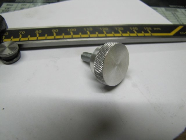
Carl, thank you ;D - Yes, it did go well; much better than expected! - Thank you! OK, I'll admit it... :-[ I bought the thumb screw from a local company called AMESS. I like supporting the underdogs, so I gave this upstart company a try; the service level can definitely be improved, but the rates were reasonable; apparently they use scrap to make bits 'n pieces. The name reminds me a bit of my own workshop... When I asked, the proprietor told me the name comes from "Arnold's Model Engineering Supply Services". Not many Arnolds involved in engineering here in Namibia though... AMESS's marketing strategy and business sense seems to be a bit of a mess though... ;)

Helder, thanks for checking in ;)

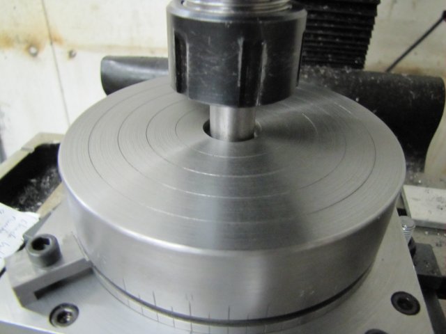
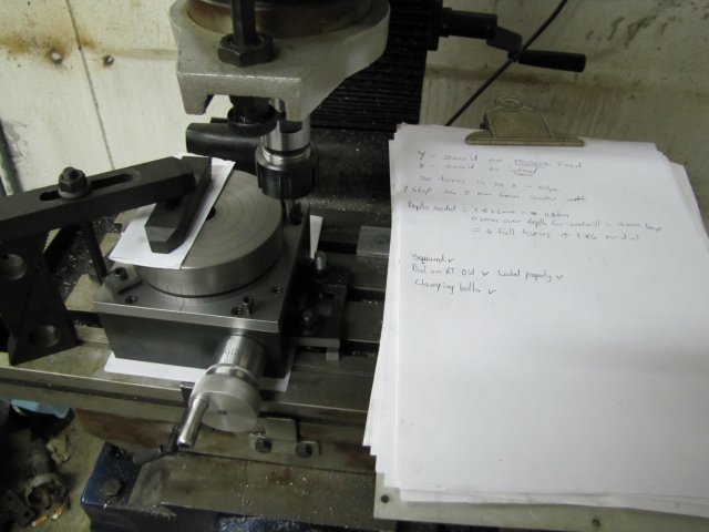
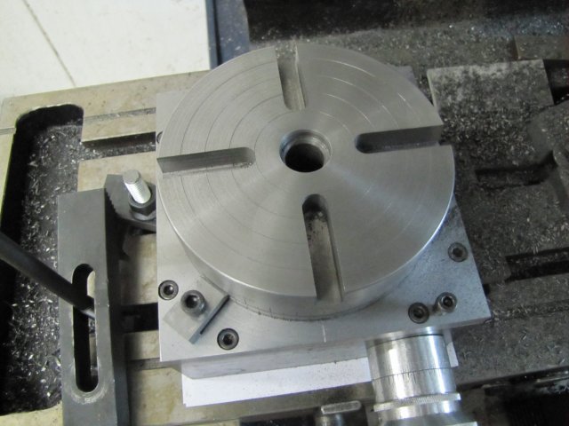
I rushed home from work this afternoon! And finished milling out the centers of the T-slots - without rushing. I followed the check list I made and the readings I jotted down to the last drop - including checking between each slot that nothing had come loose from vibration anywhere. On cutting the third slot, I had a bit of a scare; at one point the milling sounds started sounding different from the previous slots - and the feel on the handwheel was "less positive" for lack of a more "tactile" description - so I punched the emergency stop, and checked everything through again. I found that the drawbar had worked slightly loose. I try not to over tighten the drawbar on my mill's MT4 spindle; well, I'd under-tightened it, and the collet chuck had come loose in the spindle... Fortunately I caught the problem in time, and just re-tightened the drawbar; I could not even see any abnormality to the slot caused by the chuck coming loose, so I carried on. The result:
normal_IMG_1385.JPG


Finishing the three slots left after yesterday's one took me less than 45 minutes to do, and I was feeling both alert and relaxed at that point, so I decided to push on. I changed to the T-slot cutter. To find zero on the Z axis after changing the cutter, I unlocked the feed wheel, and used the drilling arms to lightly pull down the quill to the point where the cutter touched a piece of paper on the RT. Then, without locking the Z feed wheel, I cranked it to zero (in down-feed direction to compensate for some backlash) and then locked it on, and used it to reverse the quill. My mill's Z feed is not zero-able otherwise... I guess I'll be making another zero-able handwheel in future!:
normal_IMG_1387.JPG


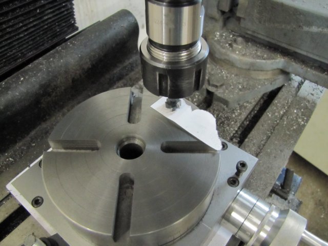
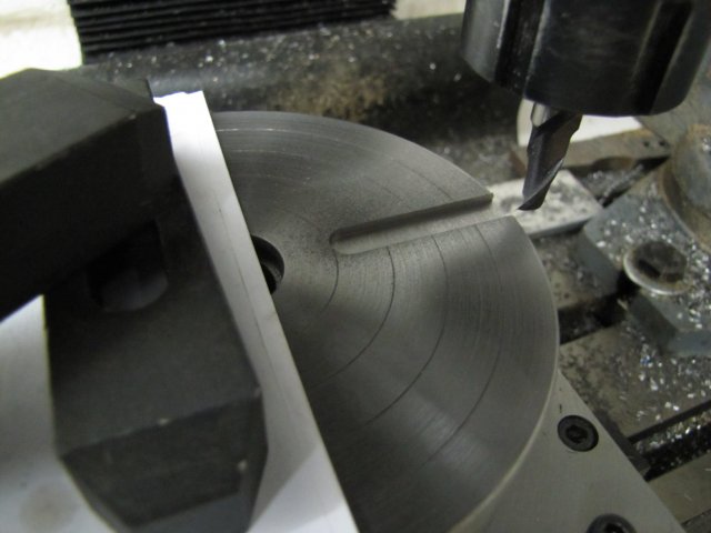
My T-slot cutter's diameter is too small for my exact requirements, and it also cuts a slightly too high undercut for the slots. I wanted the slots on the RT to match my Myford's slots, and I had to have a compromise. Well, if I made the cutter myself that would not have been necessary, but with the bought one it was. With the smaller cutter diameter, I had to offset the cuts to get enough undercut on both sides, rather than finishing in one pass.
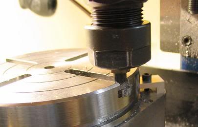
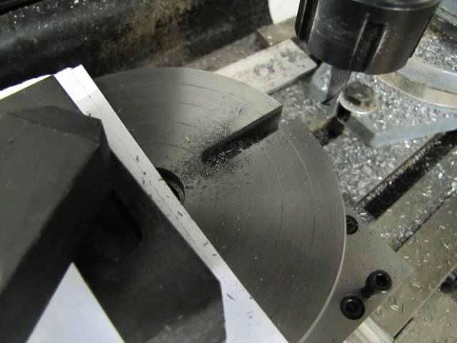
For one pass, things were A-OK; I could feed in on the Y axis and do the pass with a nice conventional cut. The opposite side was a problem; I would be climb-milling. I dug in with the first cut, and to try to get a conventional cut on the return on the opposite side, I tried back-feeding on Y while at the deep end of the cut on X. Things just did not feel right, and the cutter was "complaining"... So I reversed the Y back-feed, brought the cutter out on X and tried the climb cut with two passes on Y. It worked with a slow and steady feed ;D - and I finished the first T-Slot:
normal_IMG_1388.JPG


The other three T-slots were formalities, except the last one... I had to keep telling myself to "Keep it steady; don't rush; pay attention" on the last cut; it seemed to take forever but was at the same speed as the others!
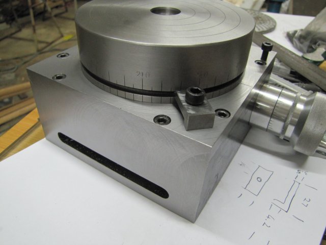
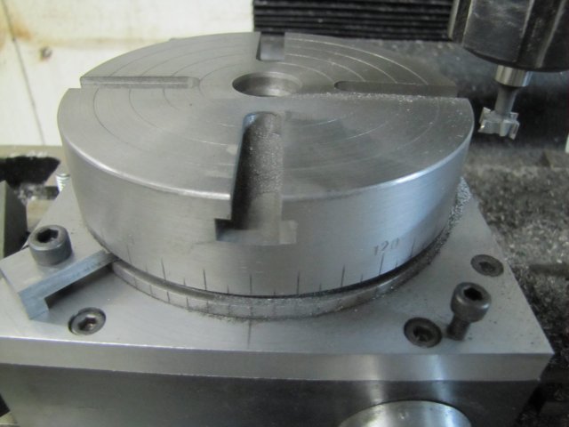
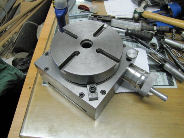
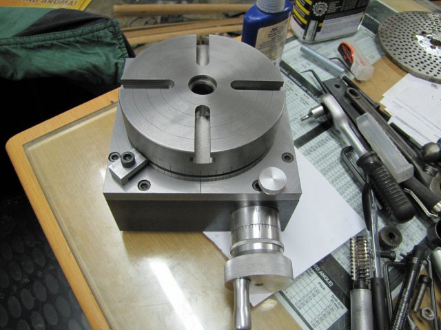
Everything came out well though, and this is the result (with the "shop bought" thumb screw added ;) ):
normal_IMG_1389.JPG

normal_IMG_1390.JPG


For those who swallowed the obligatory Dramamine or ate a bit of ginger:
[ame]http://www.youtube.com/watch?v=7PitwaclZT4[/ame]

The RT is now pretty much operational; I will still finish it with a bit of lapping like Dean demonstrated in his build, as well as add a couple of other "touches". In fact, I'm pretty pleased with the outcome up to now, and with not much left to go wrong, I broke out the VSOB and had a good glass of Chivas on the rocks to celebrate ;D - My apologies if this post was a bit "under the influence" :-[

The "chuck adapter" for the RT to take my lathe chucks will still be quite a bit of work though!

Regards, Arnold
 
Arnold. That is magnificent. Bravo on a truly inspiring piece of work!
 

Latest posts

Back
Top