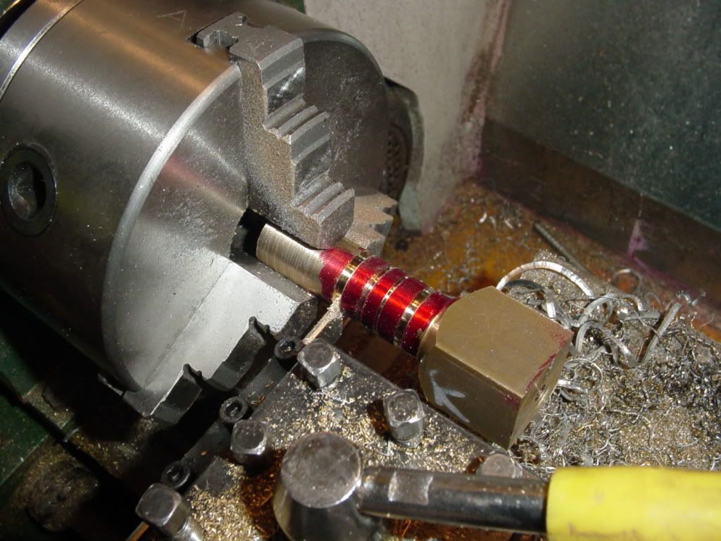
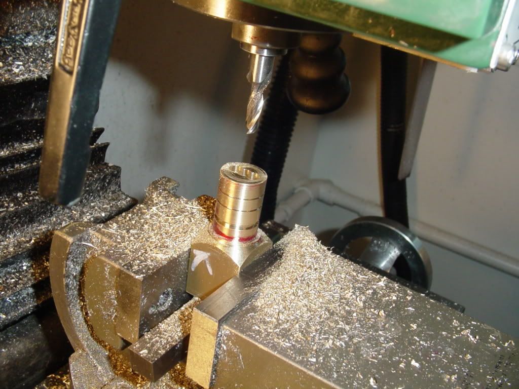
This is something I forgot to show in my detail drawing.--A couple of grooves to hold lubricating oil, about 0.015 deep by 45 degrees on the cylinder. (in this picture I have parted the square end off and clamped the round part in the 3 jaw chuck.)
Now here is the part I like--Since I still had the square shank left on one end after parting off, that gave me something to hold in my milling vice. I set it up in the vice and milled the slot and it was nice and secure.
Brian, now I will have to up my life expectancy to 189 years just to keep up with your project that I would like to do, been doing copy and paste, thanks again for sharing your knowledge and skills, that is going to a cute engine, thanks again, Lathe Nut
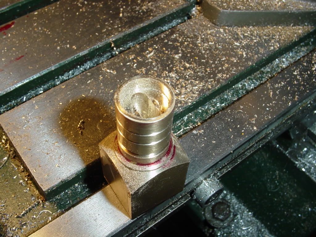
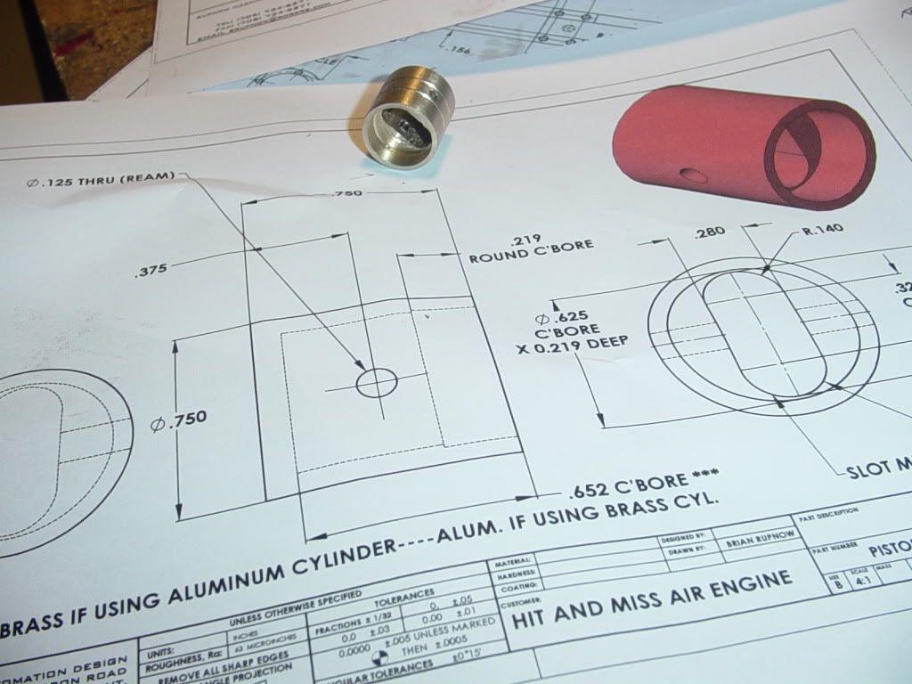
Now we have a finished piston. This is a complete reversal of the standard "Brass cylinder and aluminum piston". What was my reason for doing it this way?---Only that I had brass and aluminum in stock to build it this way, and didn't want to spend money to buy more material. From an engineering viewpoint, probably its better the other way, because an aluminum piston weighs much less, therefore would have much lower reciprocating inertial force, but for these little demonstration engines, I doubt it makes any difference.
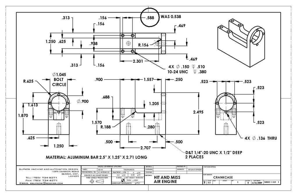
I just found a mistake on the crankcase drawing. (Yeah, I do make mistakes!) The hole centers for the bearing blocks should be 0.588 not 0.538 as previously posted. This drawing is updated---I will fix the download later .---Brian
Excuse my question...very little experience...but what is turning the part? Is there a pin or something on the end of the part that the chuck jaw is against?
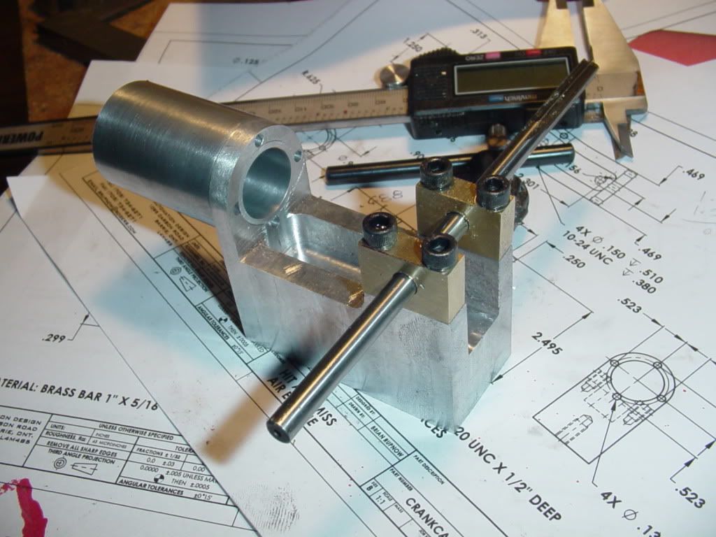
And for this afternoons offering---a pair of brass bearings. It was while drilling and tapping the crancase for these that I discovered the mistake in the previous post. At least I got lucky and discovered the error in the hole spacing on the crankcase BEFORE I drilled and tapped it!!! Glad I didn't drill and tap the crankcase first and THEN go to make the bearing blocks.
Excuse my question...very little experience...but what is turning the part? Is there a pin or something on the end of the part that the chuck jaw is against?
Zee--I wondered if anybody would pick up on that!!! Yes, when I centerdrilled the end which sets closest to the chuck I put a 0.125 hole in one corner and stuck a peice of 1/8" x 1.5" stl. rod in it. One of the chuck jaws riding against the side of the pin turned the part. That is my secret trick for avoiding having to change to and use my 4 jaw chuck.)
No, I haven't deburred anything yet. All my tooling is well used (read that as dull to really dull), and it pulls a horrible burr on aluminum. When I get a peice off the mill, I set it up in my workbench vice and flat-file all the offending burrs so that they won't give a false reading in a further set-up, but the sharp corners will remain untill I get to the "cosmetic" stage of the project. They are not really as sharp as they appear in the picture--not to the point where they would cut my hand. I will eventualy use some medium emery cloth to "break" all the sharp edges, prior to polishing.
I visited your site... it is really sad that this recession had left you without works to do... but at least we have this well documented engine here to see
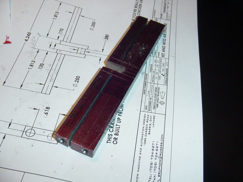
I am going to try something new and rather terrifying---machining a crankshaft from solid. I have these two instruction sheets prepared by Chuck Fellows, and since this is a relatively simple crankshaft, I will try it and see what happens.
This engine is going to be one of my summer projects. I had intended to integrate the Fellows and Superfast plans but, after seeing your fine work, I'll be using your plans.
I printed some of the plans out last night and they are truly professional. Like you, I prefer to have a complete picture of what I'm going to build before I start and your plans are very comprehensive.
My thanks (and a karma) for your hard work and your willingness to share so freely.
Marv---For someone like myself to get a karma point from a man as knowledgeable as you are about all things mathematical, I consider it a great honour. Thank you. (And thank you kindly for the karma point!!!)---Brian
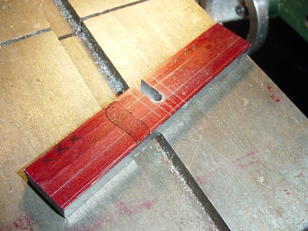
So---This afternoon was a brand new learning experience for me. After reading as much as I could from those who have boldly gone before me, I set out to machine a one peice crankshaft. I followed Chuck's guide drawings, and layed the crankshaft out on a peice of 3/8" x 1" cold rolled steel barstock, then drilled and sawed out the center. The 3 x's are there so that I take all of my measurements from the same side of the bar during layout.
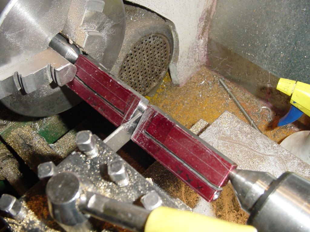
Then it was over to the lathe and mount the bar between centers to turn the connecting rod journal. If you look at the end closest to the chuck, you can see that I have a peice of 5/8" round stock with a 30 degree taper turned on the end of it to become my "center" in the chuck. I was able to slide the end of the bar between 2 of the jaws, and that was what actually made the part turn. I found it VERY SCARY to cut that journal with the cut off tool stuck out about a mile as shown in the picture.---and Oh, Yeah---I made the crankshaft 1" longer than I needed so that I could cut off the ends with the center drill holes in them and still end up with the finished crankshaft the correct length.


")