Brian Rupnow build--Hit and Miss air/steam engine

Home Model Engine Machinist Forum

Help Support Home Model Engine Machinist Forum:

This site may earn a commission from merchant affiliate links, including eBay, Amazon, and others.

Brian Rupnow

Design Engineer
Project of the Month Winner
Joined
May 23, 2008
Messages
15,005
Reaction score
8,302
Location
Barrie, Ontario, Canada
This might end up being a long thread. I started it over on the "Break Room" under the heading "Hit and Miss Steam Engine???"
http://www.homemodelenginemachinist.com/index.php?topic=5150.0
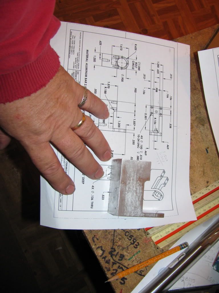
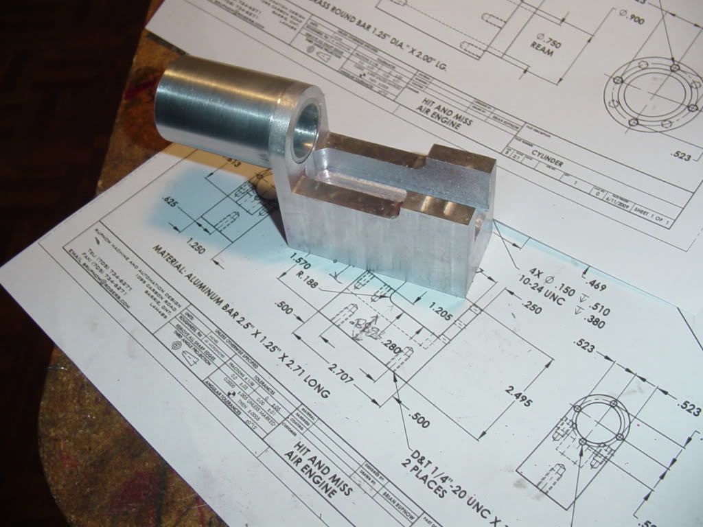
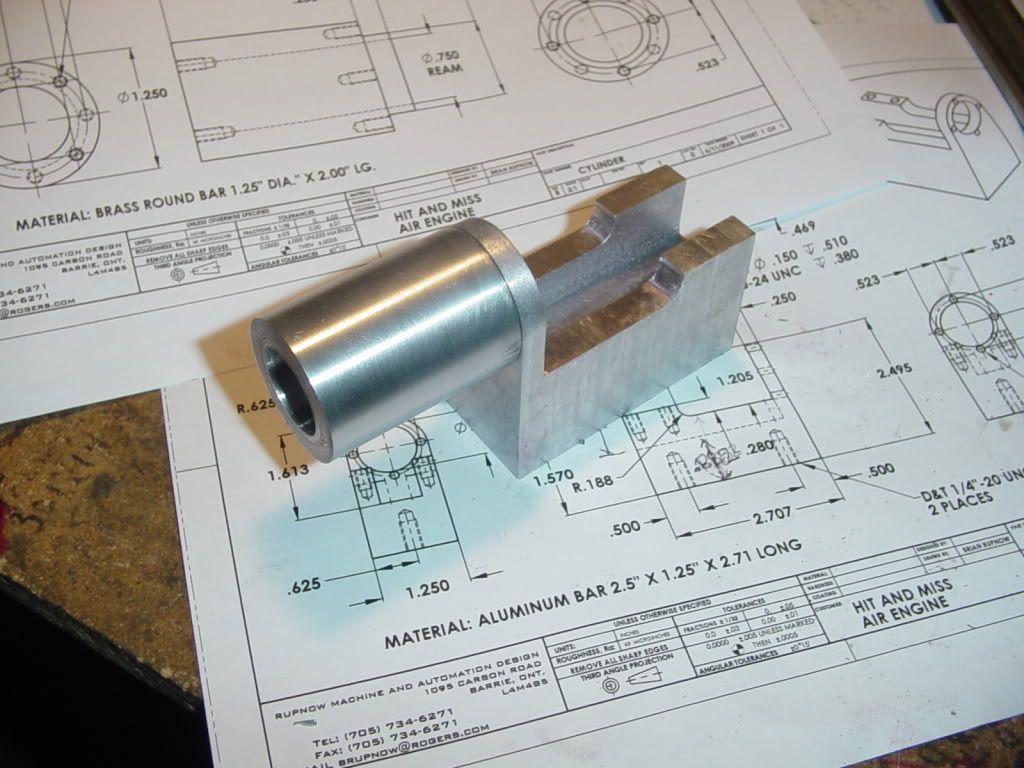
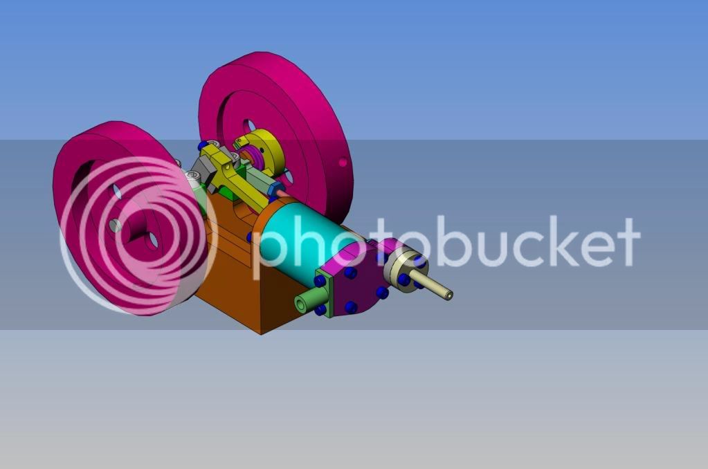
Then drew up mechanical details and posted them in the download section.
http://www.homemodelenginemachinist.com/index.php?action=tpmod;dl

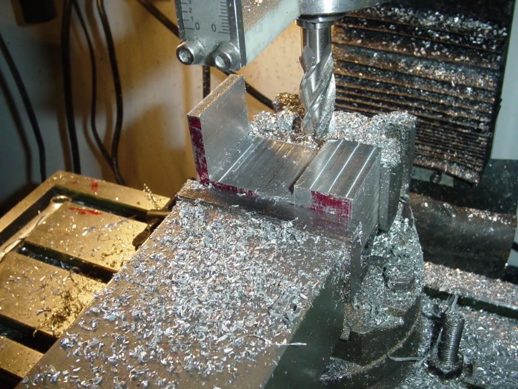
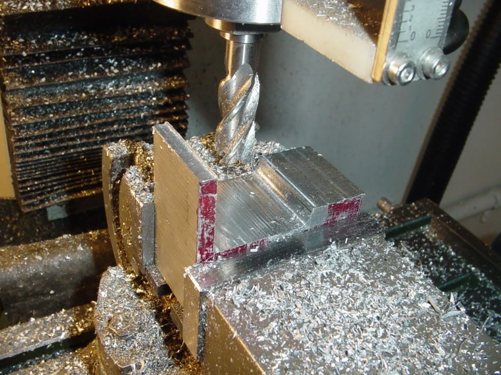
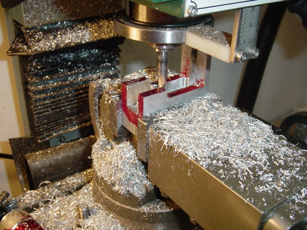
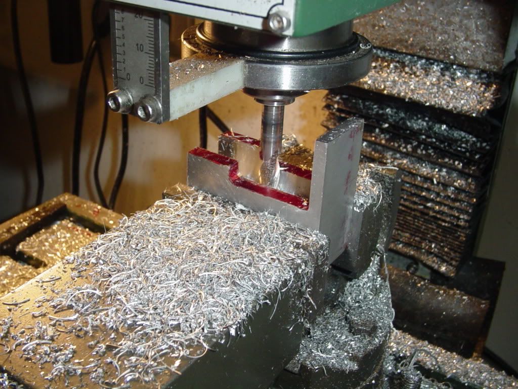
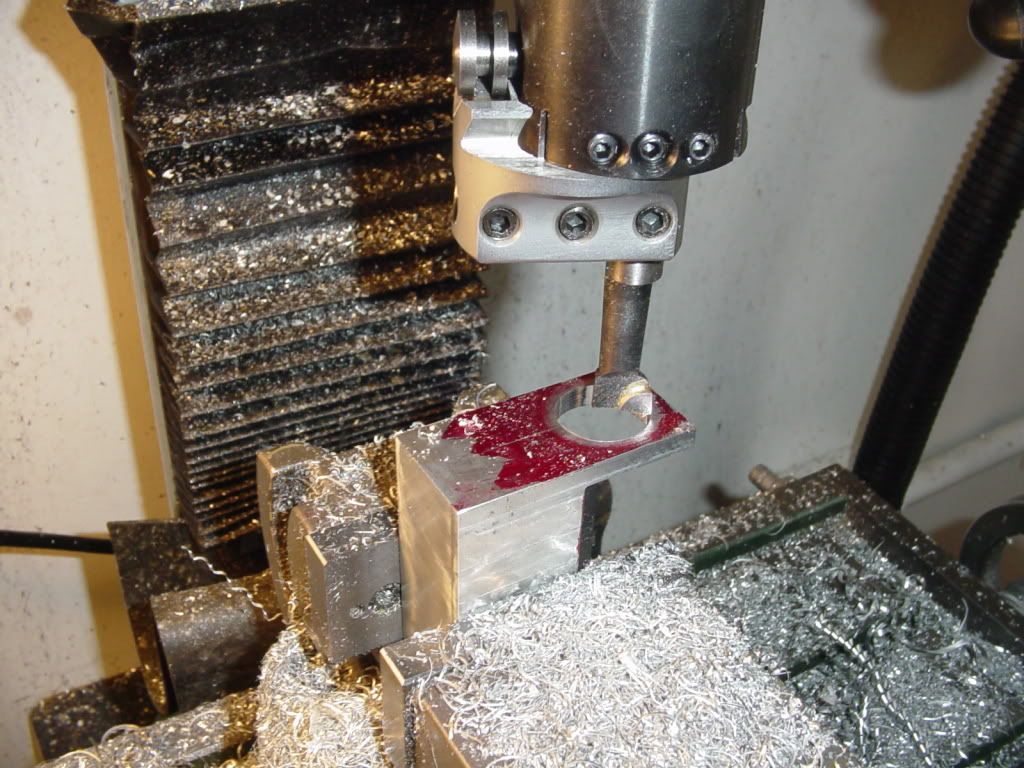
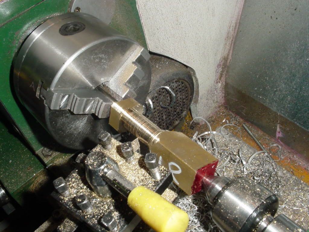
And today I started whittling out parts.
ISOVIEWHITANDMISSAIRENGINE.jpg
 
Brian,

Welcome back to swarf makers inc. :bow: ;D

Best Regards
Bob
 
Thanks Maryak---Here we have the crankcase roughed out on the bandsaw, (the radiused was put in with a 3/8" drill thru) ---and a bit of blatant advertising.
BUILD-2002.jpg

BUILD-2003.jpg


Welcome back to chip making. Looking forward to the build. I enjoyed your "Beam Engine" build a very much.


Ron
 
I didn't plan on doing this untill fall.---But---sadly, there is absolutely no engineering work available to fill up my days. This damned worldwide recession has everybody terrified to spend any money on new machine development. My hotrod (my other hobby) is finished, so there is really nothing to do on it. I will thrash away at this untill some real work comes along to take up my time. (Sure am glad I've got a rich wife!!!)
 
So today I undertook the first step in actually machining the crankcase. I used a 5/8" diameter 4 flute end mill and milled to the lines that were scribed when I layed the crankcase out. I snuck up on the lines, then measured with my vernier caliper when I got real close to the line, so as not to cut beyond the line.
MILLCRANKCASEPROFILE001.jpg

MILLCRANKCASEPROFILE002.jpg
 
Son of a gun! This thing is small. (but bigger bore and stroke than Elmers engines.) Thats the one thing about designing in 3D--Its hard to get a "feel" for how big or small something is from just the 3D cad model. I know that in my "full size" machines that I design, I have a "full size" model of a man which I insert into the assembly model so my customers can get a sense of "how big" the finished machine will be.
SMALL002.jpg
 
Good start, there, Brian. I like the looks of the drawings in the background, too!

Chuck
 
Thanks Chuck. Your little engine has inspired a lot of great builds. I know I have seen builds by you, Putputman, Superfast, and Brent, and probably there are others that I haven't seen. I hope that my "standard of workmanship" can come close to those who have gone before me. Hopefully with the plans I have done up and put in the download section, there will now be even more now. Again, my thanks for being the originator of this great engine.---Brian
 
Here we are putting the slot in the center of the crankcase. I got this far and realized that A--I don't have a 5/16" end mill to get the 0.156 rad called for on my drawing, and that B--I had a 3/8" end mill but it was too short. (I've had that problems in other areas as well, but thats another story---). So--as usual, I cheated. I used my 3/8" end mill (which ends up giving me a .188 rad instead and I slid a 0.34" long spacer into the collet before I put the endmill into it, to make the endmill long enough from the collet shoulder to the end of the endmill. This is probably a horribly dangerous and inadviseable thing to do. but it solved the problem, and it worked well.
SLOTINCRANKCASE002.jpg

SLOTINCRANKCASE003.jpg
 
Nice start! One day I'll build a hit-n-miss...

Brian Rupnow said:
...I know that in my "full size" machines that I design, I have a "full size" model of a man which I insert into the assembly model so my customers can get a sense of "how big" the finished machine will be.

I guess that's the little guy on the back of your business card?
 
It's really starting to look like an engine, don't stop now! :big: What's wrong with the center hole on your boring head?

Your drawings look great, the fact thay you do this stuff professionally really shows. :bow:
 
vlmarshall said:
It's really starting to look like an engine, don't stop now! :big: What's wrong with the center hole on your boring head?

Your drawings look great, the fact thay you do this stuff professionally really shows. :bow:

I don't understand what you mean about the center hole on the boring head.
 
Oh, just that you weren't using it, and have the boring head cranked out a good distance. Is there an operational reason for it? I'm guessing that, like some heads I've seen, the center hole is a different size.

Just an offhand question, really, I'm always looking to learn new things.
 
Okay, a perfectly good and logical question. The last time I used that boring tool was to bore a much larger hole. This time I grabbed it, put it in the collet, and screwed it in untill it fit the 3/4" clearance hole that I had drilled in the part. I never even thought about using the center hole, -----but put that one down to a "Seniors moment".
 
This evening I've been making the piston. I have no idea whether I'm going about this correctly or not, but its working, so it must be okay. I have a peice of 1" brass plate about 4" square, so first I cut a 1" wide strip off the side, center drilled the ends, set it up between centers and turned it to 0.75" dia. (You can't see it but there is a center gripped in the 3 jaw chuck.)
PISTONMACHINING001.jpg
 
Back
Top