Brian builds Atkinson Engine

Home Model Engine Machinist Forum

Help Support Home Model Engine Machinist Forum:

This site may earn a commission from merchant affiliate links, including eBay, Amazon, and others.
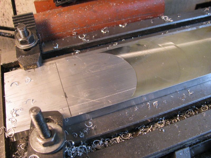
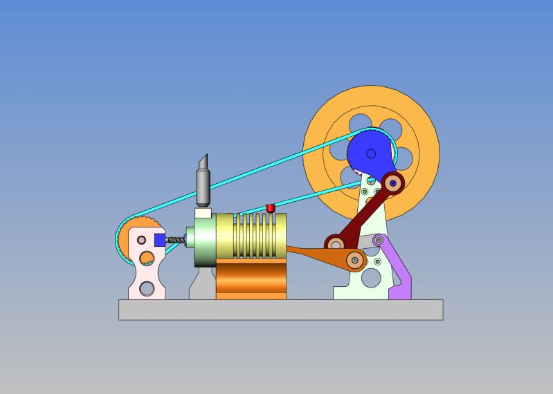
I have made a somewhat arbitrary decision to go with a 5" diameter flywheel instead of the 6" one in Jan Ridders plans. Why?---Because I happen to have a peice of 5" diameter x 1" thick brass that cost a small fortune left over from my Donkey engine build. I will leave the web a bit thicker than Jans plan, to add some mass. My rational is that if it works that way, I'm ahead of the game. If it doesn't work, I will buy a 1" length of 6" o.d. x 5/8" wall steel tube and shrink it onto the o.d. of the brass. I have made many flywheels with aluminum centers and a brass outer ring and they worked fine and looked good.
ASSEMBLY--OVERALL-SMALLFLYWHEEL.jpg
 
Brian,

I've followed your posts since I signed on in 2008. Your drawings and build pictures are truly top drawer stuff. And I agree that what we do is for our own enjoyment -- it's a hobby and the hours put in are supposed to be for our own relaxation.

Yeah, we both have noticed that the number of posts per day have fallen off big time since the switch. Really too bad there is a lot of talent out there.

Can't say as I've ever contributed much other than the occasional comment. I have made several engines over the past six years and I guess it's about time I posted the build sequence for at least one of them.

Keep up the good work

Ernie J:)
 
Tomorrow I hope to make a start on two of these main flywheel shaft supports. They are approx. 2 3/4" wide x 6" tall, and are 10mm thick. (0.394"). I have purchased a peice of 3" x 1/2" aluminum flatbar and tomorrow I hope to have an adventure in flycutting to reduce them from 1/2" to .394". I have very limited experience with flycutting, and the set of 3 flycutters that I bought 4 years ago all have brazed carbide lathe tools as cutters, which require that I run my mill in reverse. I bought a peice of 5/16" square HSS yesterday, and hope to grind my own tool which will allow me to run my mill in its normal rotation. I get much better finish results cutting aluminum with HSS than with carbide. Normally, to reduce material thickness I use a 4 flute 1" diameter end mill, but of course it leaves "tracks" a minimum of 1" wide, which have to be filed or sanded out after the fact. I'm hoping that with a 1 5/8" radius "sweep" of the flycutter that I can cover the entire face of the 3" bar with one pass.
CRANKSHAFTMAINSUPPORT.jpg
 
Good luck with the flycutting. It is something that I need to do more of as well. I can only think of one time I set up to do it...
 
This is a big OUCH in the wallet!! The plans call for all ball bearings on the shafts, and I ordered them yesterday from Canadian Bearings

Unless they are exotic sizes or grades, that does seem quite expensive just looking at what you have laid out in the pic. I've used this company in the past & they shipped reasonably to Canada USPS if requested if memory serves. It might take a week, but with a bit of foresight still worth it. See if your sizes are there just for comparison.

http://www.vxb.com/Merchant2/merchant.mvc
 
What about roughing the stock with the endmill and then a finishing pass with the flycutter?
.
Thats not a bad idea Kvom. Thats about 7 passes at .015" deep x 3" wide=021 passes. I don't know how deep a cut I can take with a flycutter as opposed to a 1" endmill. I think my maximum depth of cut with the endmill is about 0.015"
 
This morning I put in the counterbores for the camshaft bearings, and the boring Gods were with me.-Not too loose, not too sloppy--a good (lucky) result. I completed the shaft which I made 1/4" diameter in the center to suit my 1/4" reamer which I will use when I make the two cams, but both ends were turned down to work with the 6mm diameter ball bearings. I also made up the spacer which fits between the bearing and the toorhed pulley (which I don't have yet.) You can see some of the "gore" marks left by using a carbide boring tool to scallop the sides of the end stands. Thats why I prefer to work aluminum with sharp HSS. I will have to sand those marks out. I will try not to use carbide tooling when cutting aluminum fron now on. It does look like Jan Ridders drawing, so I am pleased with the result. Now----On to the fly cutting saga----
camshaftandspacers001.jpg
 
An alternate option for the camshaft bearing placement would have been a sliding fit held with green loctite, and using the shaft through the bearings to ensure alignment while the loctite cures.

I have very good results boring aluminum with carbide inserts; those brazed bars are less than ideal.

For finish cutting with a flycutter I tend to use a DOC of about .003-005" in any material. I suspect that with aluminum you can take a fairly hefty cut. I'd still rough with the endmill.
 
Last edited:
Just beginning to mess around with a newly ground flycutter. What becomes apparent immediately is that my mill is badly out of tram. That cutter should be cutting a full circle all the way around the center of the spindle. Its not---as you can see, the cutter is only contacting the material on the right side of center of the cut circle. I have had suspicions for some time that something wasn't quite right. Now I know. Perhaps my next adventure will be tramming the mill---Something which I haven't done before.
MILLOUTOFTRAM001.jpg
 
I took Kvom's advise and hogged away the majority of material with a 4 flute 1" diameter end mill. (lots of cranking),.020" advance on the quill for each pass.) I left about .010" of material in place for fly cutting. The fact that my mill is out of tram may have some effect on the ultimate smoothness I achieve by flycutting, but you can see the numerous "tracks" on the surface of the milled plate left by the 1" end mill. It should be better when flycut---We'll know in about 1/2 an hour.
HOGGING002.jpg
 
So there we are, with a flycut surface. Its not the "mirror finish" that I have often heard refered to, but its miles ahead of the tracks left by the 1" endmill. I'm sure that with the mill trammed properly, the finish would be a lot smoother because of a "burnishing" action by the cutting edge of the tool as it passes over areas already cut but that may be just speculation.
FLYCUTTINGFINISHED001.jpg
 
It's really surprising that after several years this is the first time you noticed a tramming issue. It's probably not out by much because otherwise the round endmills would leave a scallop cut, and a .001" edge can usually be detected by fingernail. With a good tram the fly cutter will leave circular marks both coming and going. And to be consistent end to end the cutter needs to exit the end of the stock completely.

Does your mill have a power drive on X? If not, it can be hard to get a consistent fly cutter finish without a constant feed rate.

No power drives on any axis. I have been suspicious about the tram because when drilling with long drills I can see them kick sideways a bit when entering a cut-----Something that it never did before untill about 3 months ago. I have used this little mill pretty hard. if it is out of tram, I suspect that the 1/2" ball nosed endmill I used to scallop out my popcorn style cylinders from steel roundstock for my Donkey is the culprit.
 
This doesn't show up particularly well, but here is what is happening. Since both flywheel shaft supports are identical, I have milled then both to the correct overall size. There are 4 "cosmetic" holes thru each support, so I have drilled and tapped two places #5-40 on the center of two of the outermost cosmetic holes in one support, and put #5 counterbores in the other plate. I will bolt them together for all drilling and machining operations, then seperate them and open up the tapped and counterbored holes to the finished size. By doing this, I am ensured that both plates will be identical, and cut my machining in half.
FLYWHEELSHAFTSTANDS001.jpg

FLYWHEELSHAFTSTANDS002.jpg
 
All thru-holes are drilled and counterbore for bearing is added in near side part. You can see in this picture how the holes are drilled at inside corners to give a nice radius after the sawcut for the profile are made.
FLYWHEELSTANDS-1001.jpg
 
After all the holes are drilled and the c'bore added to one side, the parts are flipped over in the mill vice. I machined a stub arbor in my lathe which was a "precision fit" into the thru hole at the top of the supports. To align the part under the spindle I cranked the x and y axis around untill the stub arbor would slide into the hole without binding. Then I removed the chuck, put the boring head in place, and c'bored this side for its bearing. Then with the two parts still bolted together I walked it over to my vertical bandsaw and cut away all the excess material,staying about .040" to .060" outside the scribed lines. Now I will clean everything up by milling "To the line". I haven't yet decided whether to mount things on my rotary table to finish off the round top or to "eyeball it on my vertical belt sander.
flywheelstands-3001.jpg

flywheelstands-3002.jpg
 
New guys---And old guys--Don't be shy about stopping buy and saying hello on this thread. So many of my old friends have left that I feel like I'm posting in a vacuum here. For long time machinists, I'm probably posting too much information. For newbee machinists, perhaps you haven't reached this stage in your machining abilities, but hopefully I am showing you some ways to do things. I am by no means a "master machinist", as I only bought my lathe and mill 4or 5 years ago. -----Brian
 
Brian

I am still following your build avidly and am amazed at the rate you do things. I enjoy the detailed descriptions of how you do things. Keep it up.

Vince
 

Latest posts

Back
Top