Ball Hopper Monitor - Casting Project

Home Model Engine Machinist Forum

Help Support Home Model Engine Machinist Forum:

This site may earn a commission from merchant affiliate links, including eBay, Amazon, and others.
I read somewhere that the FORD logo Henry Ford used on his cars wasn't his signature, but a commercially available font. Perhaps the Monitor logo also used a commercial font? You might find a match by searching for fonts from that era. Personally I don't think you need to search for anything better. The logo you have produced looks great.
 
The Monitor logo is one of those things where the longer you look at it, the more subtle things you begin to notice.

I suspect it may have been done with a pinstripe brush, the way the line thickness varies.

The person who made that logo had a very deft hand, that is for sure.

.
 
I’ve collected Monitor engines for 35 years or so. I have some info in pdf form that I can email you if you like. Contact me via pm or find the Monitor engines group on Facebook. I’ve uploaded a few things there.
First off, all vertical engines, 1-1/4 to 7 horsepower, are model VJ. That stands for Vertical, Jump Spark. Jump spark is an archaic term for spark plug ignition. Monitor HJ engines were Horizontal, Jump Spark. Monitor also built a series of heavy duty horizontal engines that are relatively scarce and feature make and break ignition. Those are known as heavy pattern engines.
The two horse short neck was the earlier of the two types. It has 22” diameter flywheels and the main casting is shorter by 2 or 4 inches. I can’t remember right now which it is.
Any how, engine number 2805 was the first long neck, built May 7, 1908. It had 24” flywheels and the longer crankcase, GB-1A. The main reason for the long neck was to reduce angularity of the rod and reduce cylinder wear. Horizontal engine have the crankshaft centerline below the cylinder centerline to do this whereas the verticals are not offset. The larger 24” flywheels just work better than the small ones.
Anyway, that’s all for now.
I’m up in Wisconsin and if you want to borrow my 2 horsepower long neck for the winter, we can talk. I have some original blueprints somewhere, too.
 
IMG_4252.jpeg
 
I’ve collected Monitor engines for 35 years or so. I have some info in pdf form that I can email you if you like. Contact me via pm or find the Monitor engines group on Facebook. I’ve uploaded a few things there.
First off, all vertical engines, 1-1/4 to 7 horsepower, are model VJ. That stands for Vertical, Jump Spark. Jump spark is an archaic term for spark plug ignition. Monitor HJ engines were Horizontal, Jump Spark. Monitor also built a series of heavy duty horizontal engines that are relatively scarce and feature make and break ignition. Those are known as heavy pattern engines.
The two horse short neck was the earlier of the two types. It has 22” diameter flywheels and the main casting is shorter by 2 or 4 inches. I can’t remember right now which it is.
Any how, engine number 2805 was the first long neck, built May 7, 1908. It had 24” flywheels and the longer crankcase, GB-1A. The main reason for the long neck was to reduce angularity of the rod and reduce cylinder wear. Horizontal engine have the crankshaft centerline below the cylinder centerline to do this whereas the verticals are not offset. The larger 24” flywheels just work better than the small ones.
Anyway, that’s all for now.
I’m up in Wisconsin and if you want to borrow my 2 horsepower long neck for the winter, we can talk. I have some original blueprints somewhere, too.

Joe-

Thanks very much for your Monitor information/knowledge base.

I will definitely be contacting you for more Ball Hopper Monitor info.

I have always wondered about the short/long neck variety.

There are so few people who own ball hopper monitors, and even fewer who have any historical or design knowledge of these engines.

I have seen some casting kits that were pretty nice, but all had 9" flywheels, which is a bit on the small side for me.

I really want to cast a ball hopper monitor in gray iron with 12" flywheels, and a 2.125" bore, and I have the foundry and material to pull that off.

I have paid close attention to the model engine ball hopper monitor engines I have seen, and I see a few corrections that need to be made, such as mounting the spark plug on the left side of the valve chamber, not on the front as seen in the 4hp kits.

I will send you a PM, and we will do some conversing.

Thanks very much for jumping in here with some good information.
I appreciate it very much.

Pat J

.

Edit:
Personal message sent to Joe Prindle.

.
 
Last edited:
I initially made patterns from wood, steel, linoleum, etc., before I became somewhat proficient at 3D modeling.

These days I am much better at 3D modeling, and I have the support of folks like JasonB, who has become superb at 3D modeling.

I have become so confident in 3D modeling that I purchased a Prusa XL, and plan on using that to make the patterns for this Baker Ball Hopper Monitor.

The Monitor has a lot of thin-walled parts, and the accuracy you can get from a 3D printed part is unprecedented.
I will be using 3D prints of JasonB's Frisco Standard helical gears, in a lost-PLA arrangement to cast those gears.

I really like manually making patterns in wood, but it has its limits with accuracy.

For complex patterns and accociated core boxes, 3D printing is the only way to go in my opinion.

Below is first sample print on the XL.
Complex model with no support structures required.

I think this printer will be ideal for printing the patterns for the Ball Hopper Monitor.
I am tempted to print full size patterns for a 4hp monitor, in pieces, on this printer.
Full sized flywheel pattern would be in four pieces for one pattern half.

.
r20230602_134745.jpg
r20230602_164259.jpg
r20230602_215007.jpg
r20230602_232734.jpg
 
The pattern on the right is about what the Ball Hopper Monitor flywheel pattern will look like.

Edit:
After checking my files, the flywheel on the right is the pattern I made for a ball hopper monitor.
I forgot I had 3D printed that.
I could reprint two pattern halves for the BHM flywheel at 12" diameter on the Prusa XL, but if the pattern below is 12", then I may just use that, since it is a pretty decent 3D print.

.
105014-rImg-3124.jpg
 
Last edited:
You might as well print it again with all the bosses, clamp lugs and core print, counter balance cutouts, etc rather than try to stick bits to that.

Wood can be just as accurate as 3D printing, just depends on what you use to cut the wood, these are all accurate including the core box


20201102_115747.jpg


20220426_171441.jpg


DSC04596_mLC7ir1syiQPgixbshuzKv.JPG


Also needs no further work to the surface unlike 3D printed ones which show the layers, just a quick blow over with a rattle can is all that is needed.

20220428_144411_cCT51NWJ2xs3TSfNQHs7Pq.jpg


Castings come out OK too

base.jpg


20210726_151502.jpg
 
You might as well print it again with all the bosses, clamp lugs and core print, counter balance cutouts, etc rather than try to stick bits to that.

Yes, this is true, and a good point.


Wood can be just as accurate as 3D printing, just depends on what you use to cut the wood, these are all accurate including the core box

Also true, and especially true if you have a CNC router.

Very nice pattern work and castings !

👍
 
Actually you could probably get a CNC gantry router with a larger capacity than than the XL for the same or less money that could be used for the larger patterns

Then with the money saved buy a 3D resin printer for the smaller parts which would give better surface quality than the XL. Add in some resin wax and you can do the really small stuff with lost wax method
 
Interesting comment about a CNC gantry router, what software would you use with that? Those wooden patterns are great!
 
Actually you could probably get a CNC gantry router with a larger capacity than than the XL for the same or less money that could be used for the larger patterns

Then with the money saved buy a 3D resin printer for the smaller parts which would give better surface quality than the XL. Add in some resin wax and you can do the really small stuff with lost wax method

There is much to be said for the CNC router, and the potential surface finishing it could provide.

On the downside a CNC router would create a lot of noise and dust, whereas my XL does not, and I run it in my office.
And some patterns would require gluing wood together, which is an extra step.
And then purchasing carbide bits when they get dull.

No doubt the CNC router is a viable method for pattern making; the question is "Is it right for me ?" (as they say in the pharmaceutical industry).

I have heard stories about the odors from the resin printers, and again that may not work well with my printer being in my office.
And I don't like handling fluids, at least for 3D printing.
I do handle resin for bound sand molds, but it requires wearing a commercial chemical respirator, which is rather a pain.
One person said my video sounds like Darth Vader is making molds; LOL.
Respirators are not fun to wear, especially in the heat.

I have considered the ceramic shell with wax, but that requires some short shelf life slurry, a burnout oven, sometimes a vacuum system, etc.

My hope is that I can use a hybrid lost-PLA method for the small parts, and get something near the quality of ceramic shell/wax without the hassle of that system.
I have seen some impressive lost-PLA results, but have not tried it.
I would use lost-PLA with bound sand, and perhaps do only a partial melt of the PLA, and then remove it manually.

Ceramic mold coat will give surface finish that rivals lost wax.

The XL will run quietly by itself unattended, and seems to be very stable as far as not bed-lifting, and recovering easily if the filament breaks, or if the power goes out.
The filament seems to have a long shelf life if it is kept in a sealed bag.
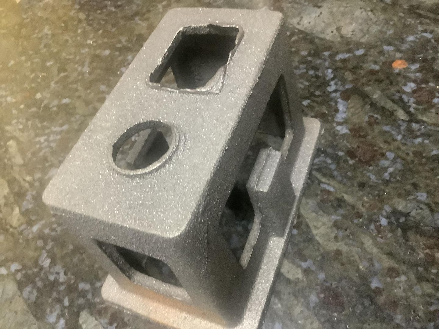
The surface finish on convex surfaces leaves a bit to be desired, but that is something I am experimenting with, to find a quick and easier solution than a manual fill/sand routine.

The polyester auto body filler seems to work pretty well, and is easy to sand with light effort, but still quite a bit of work.

I may try some sort of sputter gun that sprays out filler droplets, but that seems like a long shot, give that the filler starts to set up at some point, and will clog whatever it is being sprayed from.

I have another techinque I want to try with water-based filler on the dog, and perhaps that will be easy.

So I don't see getting away from the XL any time soon, if ever.
I do need to find a faster surface finishing technique.

.
 
Lee you could use something free like Fusion to do the CAM from a file exported from Alibre or just draw it in Fusion, the free one is good enough

Pat a gantry machine that uses a small woodworking router would be quite noisy but they can be had with small spindle motors, the water cooled ones from China are not too noisy, come with ER Collet end and with their high speed feed rates can go up and therefore run times reduced. I've not found dust to be too much of a problem when CNC cutting wood and no more that lathering on thick layers of bondo or dry wall filler to a 3D print then hand sanding would produce.

Most model size stuff could be done from solid, only the bigger parts would need glue ups but same can be said for the larger items that won't fit a 3D printer. For one offs solid timber is fine, as my patterns go to a foundry and are used multiple times then I tend to glue up the basic raw material as a form of thick "ply" which not only gives the part strength but also makes it a bit more stable if being stored in less than ideal conditions. There is also the option to use things like PU tooling board and other plastics.

I'm quite happy to leave my CNC to it and do something else or even go out of the house and as run time is likely to be shorter than 3D printing the same part I don't see time as an issue
 
I thought I would see how the different methods of making a pattern would affect timing.

This is a half pattern I did the CAD work for a couple of months ago, it is for a pulley to go on a Redwing and once machined would give a 3 1/4" dia pully. Pattern includes all draft angles, shrinkage and machining allowances.

He said the one side shown took 9.5hrs to print. plus some hand smoothing

I have just done the CAM in fusion and if I cut it on my CNC which has a max spindle speed of 5000rpm it would take just under 3 hours from a solid block of wood. This could go straight to casting

If it were to be done on a CNC with say a 20,000rpm spindle which is easily reached with a router or spindle motor then time would be 45mins, again straight to casting.

Redwing Print.JPG
 
I hear what you are saying, but I am set up for making 3D patterns with the XL, and so the die is set, for now anyway.

I have toyed with the idea of casting patterns in 356 aluminum, without filling the 3D printed pattern, and then buffing out the aluminum pattern with a sanding sponge, but the grooves can be surprisingly deep, and can't really be completely buffed out without digging very deep into the castings.

No doubt there are some advantages to the router system, if you are set up for that.

Ultimately I want to make permanent patterns in aluminum 356 for the ball hopper monitor, and perhaps make them accessible to some of the more serious builders.
I don't want to see another set of BHM patterns vanish into the ether, never to be seen again, and I don't really want to see another one-off casting like Myfordboy did, again with patterns that are never seen again.

And I am contemplating making match plates too, in aluminum, but am not sure exactly what those would look like.
The flask setup for bound sand is not the same as for greensand, and the traditional rectangular flasks are not necessarily used for bound sand, since that tends to be very wasteful.

It would be nice to have the runners and gates cast into the match plate, but then that would lock folks into that style of system.
The beauty of bound sand molds is that it is easy to cut the runners and gates after the mold sets, and if adjustments need to be made, then a permanent mold does not have to be modified.

I will work on some smoothing techniques, using the XL 3D printed dog as a test subject, and using water-based filler.
The water-based filler (sheetrock wall patching compound) is a temporary thing, since it will eventually start breaking off, but the idea is for the 3D printed pattern to only last long enough to make a permanent pattern in aluminum.
The test will be to smear on the wall patching compound, let it partially set, and then wipe it down smooth with a damp cloth, such as I have done with filling things like the Phoenix pattern.

.
 
As we have found recently with some of the Alyn Foundry patterns that were on match plates, different foundries use different size flasks so what matchplate fits one foundry's flasks may not fit another's so they need to be reworked.

The CNC, even a half decent gantry one can knock the patterns straight out of aluminium so no second guessing the initial shrinkage rate or surface prep and on my machine not a lot slower than cutting wood.

20220724_083912.jpg
 

Latest posts

Back
Top