Ball Hopper Monitor - Casting Project

Home Model Engine Machinist Forum

Help Support Home Model Engine Machinist Forum:

This site may earn a commission from merchant affiliate links, including eBay, Amazon, and others.
Looking at the Frisco Standard cam profile, it also has a broad flat top.

This puzzles me because I have seen some of these scale engines with rather pointed tops.
Perhaps I am looking at the wrong cam profile on some of the builds.
Could it be I am looking at the ignition cam with the pointed top?

.
FRISCO-STANDARD.jpg
 
The commercial engine cams all look to be symmetrical.

The Briesch Olds cam looks very odd, and asymetrical.

What is up with that?


The Galloway 1/3 scale cam is almost symmetrical, but not quite.

.
 
According to one motorcycle engine reference book I found, "Cam design is, in fact, quite a complicated business".

The slope of the lobe is going to affect the speed and accelertion of the valve.

Height of the lobe affects the amount of lift.

The width of the top of the lobe will determine the duration of valve opening.

The higher the acceleration of the valve, and I guess the higher the valve velocity, the stronger the valve spring must be to return the valve to the closed position.

A smooth transition would be needed to prevent slamming the valve open and shut.

The operating speed of the engine will affect the cam design.

.
 
Pat as I mentioned briefly in my previous post the cam's for engines with ignitors are very different to those with a spark plug as they need to move the pushrod in two stages one to close and then trip the ignitor and then the second to move the rod further to operate the exhaust. Both the Galloway and Frisco Standard and probably the olds use ignitors so you are not comparing like with like as the baker engines are spark ignition so the cam only needs to operate the valve.
 
Pat as I mentioned briefly in my previous post the cam's for engines with ignitors are very different to those with a spark plug as they need to move the pushrod in two stages one to close and then trip the ignitor and then the second to move the rod further to operate the exhaust. Both the Galloway and Frisco Standard and probably the olds use ignitors so you are not comparing like with like as the baker engines are spark ignition so the cam only needs to operate the valve.

Jason-

I missed that completely.
Still soaking it all in.

.
 
Here is the Frisco Standard.

It would appear that the larger cam operates the exhaust valve (the valve nearest the exhaust pipe), and the smaller cam operates the intake valve.

The igniter is operated by a crank on the top of the rotating valve rod.

I don't see any connections between the cam that operates the exhaust or intake valve and the ignitor, so that does not align with what you are saying.
It would seem the cams have nothing to do with the ignitor, other than being on the same shaft as the crank arm that operates the ignitor.
(Not my photos).

0809060028_JPG.jpg
0809060030_JPG.jpg


See 2:12 in this video:
The video can be seen better if you slow it down to the .25 speed.


Also see 0:12 in this video, and slow down to .25 speed.

It seems odd that the intake cam is significantly smaller on top than the exhaust cam.

The little cam at the top I think is for starting, and you use the lever I think to raise the roller follower.


Pat, I was talking about the majority of ignitor equiped hit and miss engines where a single pushrod operates both the ignitor and the exhaust valve such as the Galloway, Vertical R&V, IHC vertical and the Olds

You can see here the one rod doing both in image sbelow

Nothing odd about having different cam lift/duration between inlet and exhaust, watch any atmospheric inlet valved engine like the Monitor and you don't see much movement of the inlet valve, maybe 1/10th of what the exhaust valve opens.

IMAG2075_zpsc22e1f1f.jpg


DSC03486_zpsacibkx0j.jpg


PICT0311.jpg
 
Watch the valves on the Horizontal R&V I built you can see the exhaust valve has a lot of movement yet there is very little movement on the inlet. So on something like the frisco it would not need as much cam lift as th eexhaust.

 
This is the cam for an engine with igntor and exhaust valve both operated by the same cam you can see that not only does it do the exhaust but also "fires" the ignitor.

ignitor cam.JPG
 
That is interesting.

I am still not even close to having any sort of a comprehensive understanding of IC engines, but you have to start somewhere I guess.

I would guess that if the exhaust valve were actuated by pressure alone, it would not move very much either, but would probably move more than the exhaust valve.

I suppose that the combusted gasses take up a lot more volume than non-combusted air/gas mixture, and thus holding open the exhaust valve for a significant amount of time at an elevated position makes sense.

Any unrelieved exhaust gasses I guess would clog up the next combustion cycle, so I guess it is good to be generous on the release side of things.

For a steam engine, the release is somewhat early to make sure the pressure has time to be fully relieved.

.
 
Technically a single lever actuates both the ignitor, the exhaust valve, and the intake valve on a Frisco Standard, but that is a rotary motion, not a linear motion.

.
Pat as I mentioned briefly in my previous post the cam's for engines with ignitors are very different to those with a spark plug as they need to move the pushrod in two stages one to close and then trip the ignitor and then the second to move the rod further to operate the exhaust. Both the Galloway and Frisco Standard and probably the olds use ignitors so you are not comparing like with like as the baker engines are spark ignition so the cam only needs to operate the valve.

I need to see this in super-slow-mo, the two stage thing.

To be honest, I don't follow at all what you are saying.

The ignitor engines have symmetrical cams with a wider top, and the spark plug ignition engines also seem to have a symmetrical cam with a much smaller top.

The ignitor should trip as the side shaft is beginning its movement, and then when the roller reaches the top of the cam peak, the valve is opened, but still a symmetrical cam.

.
 
Last edited:
This is the cam for an engine with igntor and exhaust valve both operated by the same cam you can see that not only does it do the exhaust but also "fires" the ignitor.

View attachment 150526

The Galloway I think has the exhaust valve and ignitor operated by the same cam, but that cam is symmetrical.
Am I missing something?

.
 
The exhaust has to be mechanically operated, if you had it like an inlet valve it woul djust pe held shut as you want it to open as the piston rises which will just make the gas push the valve harder onto it's seat.

Some engines like the GADE had an opening part way down the cylinder which was completely open so most of teh exhaust gas went out that way at the bottom of the piston stroke, the exhaust valve just stopped the rising piston from presurising the cylinder and let the last bit of gas out which wa sthen at atmospheric pressure. Not sure if that Frisco has something similar as towards the end it shows a lot of hole sin the lower side of teh cylinder casting and what looks like exhaust smoke?

All the ignitor engines I have made have far from symmetrical cams, the Galloway is probably one of teh closest but as this drawing shows it is bigger on the right hand side than the left. I'll see if I have a video showing the push rod working on one of the ignitor engines. Spark plug engiens tend to just be a symmetrical cam with a fairly large radius lobe or even a flat

gal cam.JPG
 
It seems like the single-cam operating the exhaust valve only, and also operating the igniter, was a very simple way to operate small general service hit-and-miss engines in the early days of gas engine design.

Much like the D-valve in steam engine design, where a single eccentric operated both the intake and exhaust.

The D-valve had its limitations, due to the limits on being able to adjust admission and cutoff without negatively affecting release/exhaust, but it was a simple design to manufacture (quite sophisticated design really, and not what I would call simple design), and it worked very well for small engines, where efficiency was not paramount.

Overly complex designs may have advantages, but from what I have seen, it is the simple and robust designs that last over time, and that hold up under difficult working conditions.

Understanding the math behind the assymetrical gas engine cam design I think will be a challenge, but obviously all the events can be plotted on a graph, just as was done with steam engines.

Here is the Stanley steam engine valve travel vs ports plotted in Excel.
A picture is worth a thousand words as they say.

.
Displacement-Diagram-Stanley.jpg
 
If the cam only operates the exhaust then it is possible to use a simple eccentric but you need to leave a good gap between the rocker arm and the top of the valve and for a 4 stroke get the 2:1 gearing with something like an epycyclic gear. You can hopefully see here that the rocker moves a lot more than the valve as it is lifting away from th evalve when the valve is closed.

 
Found an old video of my Galoway showing the ignitor being tripped.

If you watch the push rod you can see it moves in stages which correspond to the various faces of the cam.

1. It moves quite rapidly to close the ignitor contacts as the piston is rising on the compression stroke
2. slows but still moving the ginitor until the hammer releases which causes the spark about TDC
3 starts to move again taking up the gap between rocker arm and valve while the piston is going down on the power stroke
4 carries on moving to open the valve as the piston rises again towards TDC letting the exhaust gasses out
5 Returns closing the valve and carries on the rest distance to the beginning during intake stroke

 
I am sure this is not the correct terminology, but I would call that a two-stage cam action.

To paraphrase what Jason has stated in my own words, I would say:

The roller (follower?) rolls up the ramp to the plateau on the left of the cam, moving the pushrod to position #1, which is far enough to trip the ignitor, but not far enough to open the exhaust valve.

The roller then rolls across the cam top, which has a shallow slope upwards equaling the same distance as is required to lift open the exhaust valve.

There may be a constant height on the top of the cam for the duration required for the valve to be open.

The slope on approach on the left and right side would need to be steep enough to give a clean fast action to the ignitor trip mechanism, but not so steep that the roller would have difficulty transversing up the face.

The slope on the right side of the cam is probably not critical, and should give a gradual closing of the valve without slamming it shut.

So now it makes me wonder about steam engines that had poppet valves.
I would think a steam engine with four independent poppet valves would not need an asymetrical cam.

The cam on an engine like the one Jason shows in his video would have to be accurately cut, else I don't think it would function, and/or the timing of everything would be all off.

That is why I don't like to build small engines; because there is really no room for error when you go small.

That is a clever mechanism for sure.

.
 
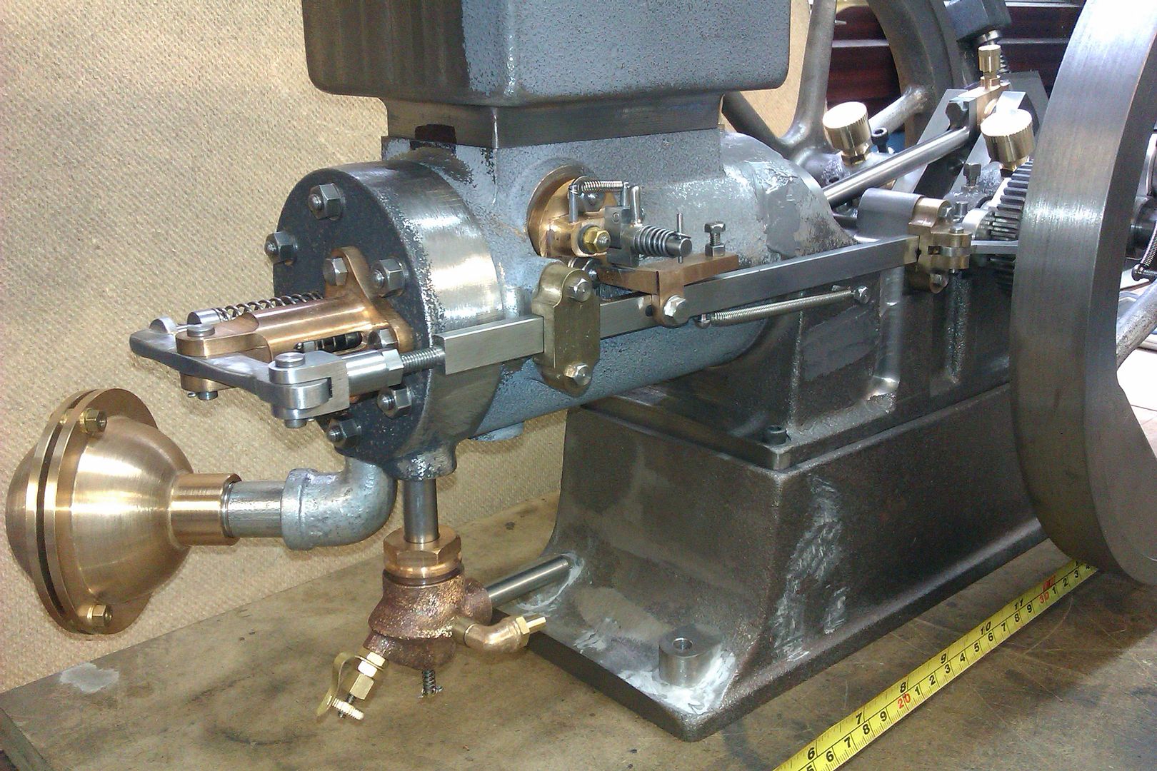
This photo really shows the two-stages better, and this is really two cams, with one superimposed on top of another.

You could actually use two cams for this, but I would guess they merged the two cams into one, since there was no overlap.

The cam protrusion on the right is the ignitor cam.

The cam protrusion on the upper-left actuates the valve.

Once the ignitor trips, the position of that actuator is irrelevant, since it trips clear of the horizontal shaft that the cam is moving.

Edit:
From the diagram, the shaft moves about 0.15" to trip the ingnitor (0.25 - 0.4).

The shaft moves another 0.12" to the point where the exhaust valve begins to open (0.52 - 0.4).

During 75 degrees and 90 degrees there is a steep slope, and so rapid valve movement.

At 105 degrees, the roller is up on the constant plateau section, at 0.625", and remains at this constant position until after 150 degrees.

After 165 degrees, there is another steep slope to close the valve quickly at about 190 degrees.

The curve between 190 and 345 degrees is just to provide a smooth transition between these two points, and could be flat, but that would hammer the roller against the cam as it would stop and begin contact, instead of remaining in constant contact with the cam.


Edit2:

You could actually use a trip mechanism on the exhaust valve, and push and lock it in the open position, and then trip it closed in the same manner as the ignitor.
This would tend to hammer the valve against the seat, but in a Corliss, the valves are opened to a point, and then tripped suddenly closed, with a dashpot under each valve actuator to absort the impact of the valve closing suddenly.
The sudden closing of the valve in a Corliss is for efficiency, since it allows the steam to expand after an early cutoff, thus using both the pressure of the steam, and the pressure that is maintained relatively well while the steam is expanding.

Edit 3:

The slope of the curve between 15 degrees and when the exhaust valve starts to open is just a way to blend gradually from one point to another without an abrupt change in slope.

.
104352-ignitor-cam.JPG
 
Last edited:
Back
Top