Balancing Engines

Home Model Engine Machinist Forum

Help Support Home Model Engine Machinist Forum:

This site may earn a commission from merchant affiliate links, including eBay, Amazon, and others.
mklotz said:
In a polar plot we have a distance r and an angle theta. We plot a point by finding the angle on the angular scale and then going out along that angle line a distance equivalent to r. The relations between x,y and r,theta are: r = sqrt (x^2 + y^2)

Yes, thats how kind of how I interpreted polar plots. In this case we have a table of data where each angular 'step' of crankshaft position has an associated X and Y centroid position. So a series of [Angle, X, Y] relationships.

Now I will volunteer my guess of a polar plot. Maybe this will be the lucky one! I find myself in a strange position of trying to 'guess the answer' here ;D I've attached Neils data & calculated R based on the square root equation. Then I plotted the [Angle,R] coordinates for 0-180 deg rotation & mirrored on the other side assuming it matches 180-360 deg rotation. (...in a high priced Cad program because apparently Excel does not offer polar plots). Does THIS help our balancing effort in any way?


2011-12-04_141509.jpg


2011-12-04_141335.jpg


2011-12-04_141451.jpg
 
I am going to have to try and simplify this problem, and maybe start with just a counterweight, and revolve it, then add an equal counterweight 180 degrees from it, then perhaps shift the angle between them.

Somehow, the plot would have to change to a vertical or horizontal line if I understand Niels correctly, when the balance is all either horizontal or vertical.

Pat J
 
Ok, here is my start of trying to figure out engine balance using Niels method.

I started with a plain crank with no counterbalances, and looked at the X, Y and Z coordinates for the center of mass (shown on the right) as I tried various positions and configurations.

I will add a counterbalance tomorrow and see what happens.

Pat J

Balance-01.jpg


Balance-02.jpg


Balance-03.jpg


Balance-04.jpg
 
It is more or less impossible to completely ballance any engine (although radials can get damn close).

In a single cylinder, if your crank ballance web matches the rotary imballance forces, then it does nothing for the forces generated by accellerating the non-rotating mass (piston and part of the conrod mass)

Maximum accelleration occurs at minimum velocity (ie TDC & BDC) and at approximately mid-stroke there is no accelleration (its about to change from acelleration to decelleration).

Adding ballancing mass reduces the vertical out of ballance at the expense of introducing a lateral out of ballance (but it does help).

The obvious way of dealing with non-rotating inertial masses is by opposing cylinders but even here they are not equal and opposite because of the finite conrod length. Additionaly this intoduces a torque couple because of the cylinder offsets which introduces a rocking vibration into the engine.

A conventional 4 cylinder in line IC engine suffers from this and in some cars this is countered by a rotating "countershaft" of eccentric masses running at engine speed to counter the remaining or introduced forces from the primary ballancing.

ballance.jpg


Above - my ballancing set up :-

A pair of stanley knife blades are near frictionless and the conrod is supported at the big end by a thin thread - obviously this method is only as good as the friction at the big end will permit so it is loose (not fully tightened) and lubricated.

Mount the whole affair on a zeroed scale - if the big end is heavy you can attatch a thin line and pull up - if its light push down.
The value on the scale gives some idea of the mass of material needed to be removed from the parralell portion of the webs (if heavy) or from the offset (if light).

By working up and down you can also see the hysteresis in value induced by the big end friction and you can average the result.

This setup moves to an imballance of about 2.5g mostly due to big end friction.

Sure this is a static ballance only but if its not statically ballanced its not dynamically ballenced either.

As per the above this method is ignoring the imballance created by accelleration forces.

I calculated the webs as per vector diagams suggested in the earlier posts.

Ken
 
Hi Ken
your pic does not seem to be working Mate
Pete
 
I can see Ken's photo.

That is interesting Ken, I will have to study that a bit more to see if statically balancing an engine produces a larger counterweight than dynamically balancing an engine.

Looking at the formula from the old book again:

W1 = [K*(W2+W3)*r] / X

We could rewrite it as:

X*W1 = K*r*(W2+W3)

or distance times mass equals K times distance times the sum of two masses.

I will think on it some more.

Pat J
 
The attachment shows a straightforward

m1*r1 = m2*r2 calculation

The mass on the left is the rotating mass of the conrod - weighed at the big end centreline whilst supporting (suspending) the small end, plus the big end pin (and any other varables such as the difference in mass of the steel pin vs the bronze webs etc.)

The mass on the right is calculated from the material density etc and the CoG - via a process of guesstimating and adjusting the width (marked "adjust") until it "ballances"

Ken


Dump_Model_2.jpg
 
A balanced engine is one where every reciprocating mass and every orbiting mass is offset by an equal mass moving in the opposite direction at the same velocity. I don't think that I ever posted this video, but here is a balanced engine. It is suspended only by the air line. The only unbalanced vibrations are torsional.


At slow speed, just before shutoff, some torsional vibration shows, which probably indicates one or more cylinders are lazy.

Jerry
 
BigOnSteam said:
Ok, here is my start of trying to figure out engine balance using Niels method. ...I will add a counterbalance tomorrow and see what happens.
Pat J

Pat, I think what you have shown is that the program is calculating the centroid properly.
Angle X Y Z pic
TDC 0 0 +0.1574 0 02
BDC 180 0 -0.1584 0 03
270 -0.1584 0 0 05

But recognize at this stage you have a situation of 100% rotating parts. The path of the centroid through 360 deg crank rotation would be a perfect circle. Balancing is relatively easy, put an appropriate counterweight on the opposing side until you get a new centroid of X=0, Y=0. You can choose a small mass at a long radius or a large mass at short radius, but the objective would be to make the circle path converge to a dot (I think).

But this is not quite an engine yet. There are no 100% reciprocating components (like a piston or wristpin) or partial recip/rotate components (like a connecting rod) which will make an irregular path. Thats where the fun begins. What I interpreted what Niels offered was a similar X,Y,Z centroid, but from ALL components. The question is then...what now?.

 
Ken I said:
... my ballancing set up .....Sure this is a static ballance only but if its not statically ballanced its not dynamically ballenced either. Ken

Im glad you provided this picture because it is indicative of what I have seen displayed in other model engine balancing articles. I notice that the piston & related 'reciprocating only' parts (ring, wristpin etc) have been removed from the assembly.

So does this satisfy the usual quoted balancing goal: "the counterweight must balance half of all reciprocating mass, plus all of the rotating mass"?
 
You “can” take a snapshot of an engine assembly with auto-cad type software, and determining center mass an engine assembly. But the information is not helpful for balancing – as only the crankshaft is in pure rotation.

To balancing an engine, you must determine the magnitude of acceleration forces, and also the direction in which those acceleration forces are applied to the crankshaft’s rod journal.

More specifically - the instantaneous piston acceleration can accurately be calculated as a function of crankshaft angular displacement, at a given rpm, using some rather involved linkage analysis calculations. This acceleration when applied to the mass of the piston, will give you the instantaneous linear force that is applied to the connecting rod. The connecting rod will then transfer this force to the crankshaft. It is this “force” that needs to be balanced out. The problem is that the direction in which the force is applied to the crankshaft changes significantly with respect to crankshaft rotation – as does the size of the force itself. Further compounding the problem is that the connecting rod will introduce its own acceleration forces into the system. Which like the piston, will significantly change in both direction and magnitude as the crankshaft is rotating. And if that wasn’t enough – the dynamic force effects of the combustion event will change the apparent mass-loading of the reciprocating components – thus if the engine is ideally balanced over the intake and exhaust stroke, it will be slightly out-of-balance during the compression and power stroke.

Thus there is no such thing a precisely balanced single cylinder engine. Even with the best achievable balance, there will always be a range of crankshaft rotation where the engine is a little underbalanced, and a range where the engine is a little overbalanced. However if done correctly, the out-of-balance acceleration forces will be minimized, and the engine will run rather smoothly.

Achieving “maximum” dynamic balance requires extensive engineering analysis. It is very time consuming, and is unnecessary for all but the highest of rpm engines. There is such thing as close counts. You can achieve a reasonable and acceptable dynamic balance using the following guidelines: the counterweight must balance half of all reciprocating mass, plus all of the rotating mass. Calculating the counterbalance mass is the easy part. The hard part for most folks is incorporating the mass correctly into the crankshaft’s counterweight design.

The auto-cad type software is an excellent tool for doing this. You can verify that your crankshaft (and only the crankshaft) has the proper counterbalance that you’ve calculated.

However unless the software contains dynamic linkage analysis algorithms, which it probably does not, you’ll gain nothing in finding the center-mass of the entire rotating assembly.

If you have the machinery to accomplish the task, you can physically attach the equivalent rotating-mass to the connecting rod’s journal, spin it up, and tweak the counterweight’s mass as needed to minimize the measured accelerations (aka, the fine tuning aspects of dynamic balancing). You still need a starting point for this process – in that the counterweights will be properly sized on paper, long before the crankshaft is even fabricated.

FWIW, single cylinder engines crankshafts are not typically dynamically balanced on a machine, because they cannot be "truely balanced". Multi cylinder engines can however be truly balanced via dynamic balancing – as is commonly done in the V-8 automotive and marine racing community.
 
petertha said:
So does this satisfy the usual quoted balancing goal: "the counterweight must balance half of all reciprocating mass, plus all of the rotating mass"?

Sort of - yes - but clearly that is a rule of thumb.

If you consider my photo with the smallend suspended the "Mass" of the conrod bearing down would be half if the conrod was symetrical (ie the small end was the same as the big end) but its not so more that half its mass is bearing down (in the photo) but that is the mass that is effectively being rotated out of ballance by the crank (this statement is not true for all angular positions due to conrod length) and along with any other rotating component - such as the big end journal must be accomodated.

If you consider all the moving masses to have two components, one rotating and one oscillating (again this is not stricly true either) then only the rotating forces can be ballanced - at mid stroke (or thereabouts) when the oscillating components are being neither accelerated or decellerated there is nothing in that component to ballance out - so additional counter weight (which might null out or reduce the accelleration forces at TDC or BDC) will be generating a force sideways - hence an out of ballance condition - hence my comment that any additional ballancing mass over static ballance (in a single cylinder engine) will diminish vibration in the vertical plane by increacing the vibration in the horizontal plane.

Having said that some overballance from static is beneficial - about half the reciprocating mass - imagine you have a vertical vector force of 1 but by reducing it to 0.5 you introduce a horizontal vector of 0.5 the new compound vector is (0.5^2)+(0.5^2)]^0.5 = 0.707 which is an improvement - so there again the rule of thumb of half the reciprocating mass.

With a single cylinder engine its always going to be a mess.

Ken
 
It will still not solve the problem of the single cylinder engine completely (impossible), but a balanceshaft can help quite a bit on a bigger engine. I have a 350 cc single as my winter motorcycle and vibrations are not a factor.

Here's a link to a simple explanation http://www.dansmc.com/counterbalancers.htm

In the original problem - if you just balance the rotational forces away, by calculating the weight of the big-end and part of the conrod - I'm sure that most of your hopping is gone.
 
Thanks very much to input from all, it is very enlightening.

I will have to drink some more coffee and re-read all the posts several times to make sure I can absorb what it being said, but I think I am getting the ideas down.

The next step for me, after verifying how the center of mass moves for a symmetrical crankshaft, and an asymmetrical crankshaft, is to add in the remaining components into an assembly, set the proper constraints, add a fixed bearing so that I can rotate the crankshaft and have the piston and crosshead move back and forth, and then again note the X, Y and Z movement of the center of mass of the entire assembly, using an approximately sized counterweight from the old formula.

I can then modify the counterweigh size slightly and look at what is happening to the center of mass of the entire assemby.

I will try and set this up in the next day or so.

Pat J
 
BigOnSteam said:
Equation for minimizing engine vibration:

Formula No.3:
W1 = [K*(W2+W3)*r] / X

where:

W1 = weight of the counterweight (lbs.)
W2 = weight of the crank webs outside of the main shaft and crank pin (lbs.)
W3 = weight of reciprocating parts (piston, piston rod, crosshead, one half the weight of the connecting rod) (lbs.)

X = distance of center of mass of counterweight from center of the crankshaft (inches)

K = constant (use 0.67 for minimum vibration at right angles to the engine centerline, use 0.75 for minimum vibration at crank dead center)

r = distance from center of crankshaft to center of crank pin (inches)

Generally, vertical engines should tend toward using the 0.67 value for "k", and horizontal engines should tend towards using the 0.75 value for "k".

Ok, my tiny mind is slowly working this problem out (I hope), and I think this is what the others have already said (correct me guys if I mis-state something below, I am still trying to understand all this).

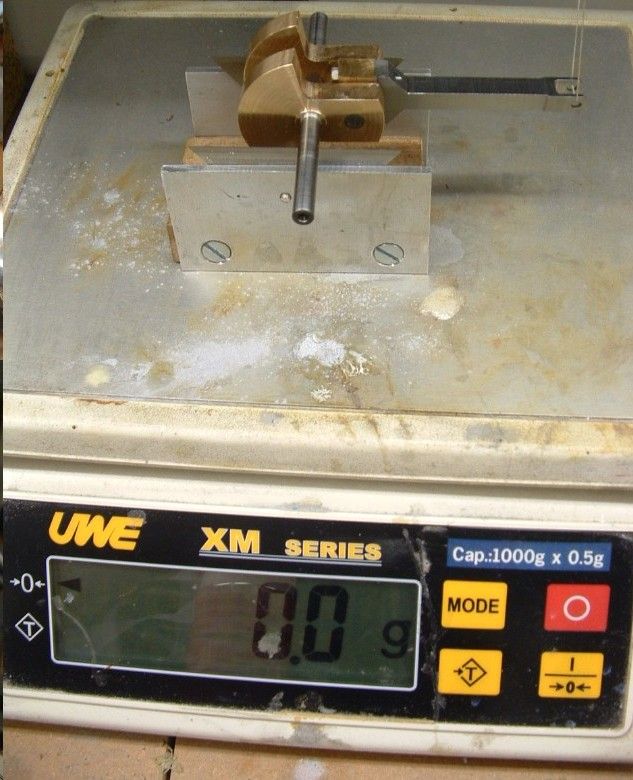
From the above equation, if we use a static balance situation, and just place the crankshaft on knife edges, with the counterweights on one side and the connecting rod, crosshead and pin, piston rod, piston, and ring hanging straight down on the other side, then we would have the counterweight mass (W1) times the distance of the center of mass of the counterweight from the center of the crankshaft (X) equaling the total mass of the crank pin plus the mass of the connecting rod, crosshead and pin, piston rod, piston and ring times the distance from the center of the crankshaft to the center of the crank pin (r), or:

Formula No.1:
W1*X = (W2+W3)*r

The assembly if statically balanced would stay in a horizontal position, like a balance used to measure weights, and in rotation, it should be perfectly balanced at TDC and BDC, but overbalanced at the crank quarters, and so would have a lot of horizontal forces (assuming a vertical engine), but not much in the way of vertical forces.

Formula No.3 (the original old formula) modifes the static balance situation by making the counterweight mass times distance "x" less than the mass of the parts on the other side times the distance "r", and the reduction in counterweight mass is half of the connecting rod weight, plus a reduction of between 25% and 33% due to the "k" constant multiplier.

So if you use the old formula, you are reducing the value for the mass on the side opposite the counterbalances by around 1/3.
If the crankshaft is on the quarter, then the formula for a static situation would be (?):

Formula No.2:
W1*X = (W2+half the connecting rod weight)*r

although the connecting rod would not be symmetrical in shape, so the above forumula would be approximate.
This formula should reduce or eliminate most of the side-to-side forces, but would result in higher vertical forces.

The counterweight required for Formula No. 2 would be much smaller than the counterweight required for Formula No.1, since Formula No.2 leaves out the crosshead, piston rod, piston, etc. masses.

So Formula No.1 (static balance) creates a counterweight that is too large, and Forumla No.2 (horizontal balance) creates a counterweight that is too small, so Formula No.3 (the original formula) strikes a balance between these two values.

Also, as others have mentioned, the crosshead, crosshead pin, piston piston rod, etc. are not revolving, so to multiply their weights by a distance "r" is treating them like the spinning ice skater who varies their speed when spinning by moving their arms closer or further away from their body, but these weights are not spinning, so there is apparently some fudging there in the formula.

The thing to remember is that balancing a single engine is at best a compromise between vertical and horizontal forces, but certainly using formula No.3 should restult in a significant reduction in out of balance forces, although not a perfect situation, perhaps an improved situation, since with no counterbalance at all, the engine will have no vertical or horizontal balance.

Pat J
 
Entropy455 said:
There is such thing as close counts. You can achieve a reasonable and acceptable dynamic balance using the following guidelines: the counterweight must balance half of all reciprocating mass, plus all of the rotating mass. Calculating the counterbalance mass is the easy part. The hard part for most folks is incorporating the mass correctly into the crankshaft’s counterweight design.

Thanks for a great reply. So specific to my immediate application, a 5 cyl radial 4-stroke, I will have a configuration like this picture. There is some latitude to making the counterweight 'wedge' shape larger or smaller (or replaceable/tweakable for that matter). Also by choosing specific materials in 3DCad, I will have a good handle on the expected finished weights of all components in real life. So along the lines of what you are saying, striving to achieve a "reasonable and acceptable dynamic balance" off the drawing board, how do I handle parts like the master rod & link rods - ie the parts that are some 'mixture' of rotating & reciprocating motion?

I'll throw out this (completely unfounded, non-engineering) thought out to see if it makes any sense or can be applied. (It's like a bad mental itch I have that won't go away ;D ...tell me if I'm barking up the wrong tree.)

- if I look at say the counterweight or the crankpin as a single element, it has a centroid, easy to spit out in Cad. If I trace that centroid through a 360 deg of crank rotation, it makes a perfect circle. So its weight gets a 'score' of 100%, meaning purely rotational.

-if I look at the piston as a single element, it has a centroid. If I trace that centroid through a 360 deg of crank rotation, it makes a line. So its weight gets a 'score' of 50%, meaning purely reciprocating.

- a connecting rod's centroid would have a path maybe like an elipse or a cam shape. Is there anything I can do with this resultant dimensional path shape that says it gets a relative weight score of say 72% & assists in how to treat it in the simple balance method? Also, if the rod was shaped real fat at the bottom, its centroid would be lower & the path would be more concentrated to the bottom end. One would think this would be useful in some way?

2011-12-05_202639.jpg
 
enginebalance.jpg


Here is machine-shop way to balance a single cylinder engine:

Weigh the small end of the connecting rod, and record this value as reciprocating mass.

Weigh the large end of the connecting rod, and record this value as rotating mass.

Note: the small-end rod weight, plus the big-end rod weight, should equal the total weight of the rod. If it doesn’t, retake the measurements, as you did something wrong.

Add up the weights of all “pure” reciprocating components (i.e. the small-end of connecting rod, the piston, rings, wrist-pin, etc). Divide this number by two.

Take the above number (which is equal to half of all reciprocating mass), and add it to the weight of the large-end of the connecting rod (the rotating mass). This number is the final equivalent mass that must be balanced out by the crankshaft.

Machine a cylinder on the lathe that weighs the same as your equivalent mass, as calculated above. Be sure to include a small eye bolt for attaching string, or dental floss.

Manufacture your crankshaft with oversized counterweights (because it’s easier to remove metal than it is to add it). Suspend the crankshaft on a set of machined parallels. Ensure the parallels are perfectly level and free of debris – as the crank must be able to roll freely with the smallest of effort.

Attach the equivalent mass to the crankshaft’s connecting rod journal with some small string, or dental floss. The rod journal’s line of action must be parallel to the supports, and perpendicular to the string (as shown). The string must be perfectly in-line with the center-axis of the rod journal. If the string is off-center, is will introduce significant error.

If the crankshaft rotates clockwise, machine away material from the red area of the crank, until there is no rotation.

If the crankshaft rotates counterclockwise, you need to add material to the red area of the crank, until there is no rotation.

Remember that a “very small” rotation is still a rotation.

The engine is balanced when there is “no” crankshaft rotation. When you get close, you can drill holes in the counterweights to “sneak up” on the final mass, in lieu of lathe operations where you can overshoot.

This method will provide more than adequate results, and permit you to run a neutrally balanced flywheel - - - in a single cylinder engine. . . .
 
OK now this i can use !!
nice one Entropy455
Pete
 
just happened onto this discussion, between vise-cleaning and fetching screws for tooling:

This occurs to me:

first: separate all the various forces, such that the crankshaft (by itself), the big end of the connecting rod as it rotates, the small end as it reciprocates - all of these, handle separately.

second: put each of these separate elements onto a polar vector diagram, with the angular displacement corresponding to the position of the crankpin as it rotates through a complete circle of 360 degrees, and the length of the vector the corresponding force;

thirdly: sum the effects of all the separate elements. This will give total force applied to the crankpin expressed through the center of rotation.

four: add or subtract weight opposite the crankpin to give the 'nearest to even' level of force through a complete cycle. Note that this will be 'best' at a range of power settings and RPM.

I hope this is clear enough to help. (If I weren't so rusty regarding programming, I'd possibly try to write a program to print the values.)

Dennis
 
Back
Top