A different opposed piston engine---

Home Model Engine Machinist Forum

Help Support Home Model Engine Machinist Forum:

This site may earn a commission from merchant affiliate links, including eBay, Amazon, and others.
Lord, Lord Molly--It must be an engine!!!-There's a sparkplug in it!!! I have spent all day working on that center part with the sparkplug in it.--Man, there is a lot of work in that little devil. Great way to spend New Years day!!

 
Seems to be coming together nicely. Do you have the ignition part figured out yet?

Cheers,
Phil
 
For the ignition I'm just going to use exactly the same CDI set up from Roy Sholl that I used on the "Rupnow engine". It works fine. it's costly, at about $100 a pop, but it seems to be maintenance free, and I still do enough "real" engineering work that the cost doesn't alarm me too much.
 
I decided that I wanted to use one of the small router guide bearings on the end of my valve pushrod similar to the way I did on the "Rupnow Engine". This meant a couple of simple changes, one being that the pushrod had to increase in diameter from 1/4" to 9/32", so that with the 1/4" diameter bearing mounted on the end of it, it could still be inserted from the top of the engine. The other change involved milling a .094" wide x 0.2" long slot in it and putting a 3/32" pin through the plate it rides in to keep it from rotating. I also drilled and tapped the rocker arm for a #5-40 bolt with a rounded contact end so that I could adjust the valve lash.
 
I have found a much better place for the gas tank. It will be made from my remaining piece of 1" o.d. brass tubing, salvaged from an old halogen floor lamp. It will be 4" long and clear the top of the flywheel by 1/16", and will bolt to the back side of the main vertical plate. I can arrange my intake manifold so the top of the tank sets just below the fuel delivery hole in the venturi of the carburetor, which must be done to prevent gravity flooding. I haven't modelled in a filler cap or neck yet.
 
Looks great Brian. I know you wanted a solid flywheel, but I think a pattern of 4 "Tear drop" cutouts would look great.

John
 
Are there to be bearings for the crankshaft in the two support plates? I’m missing something; OD of shafts is 0.3745" and ID in support plates is 0.438". I look at your assembly photos and I cannot tell if there are bearing-bushings or not.
 
I like the cam follower/valve lifter assembly Brian. It has an easy way to adjust valve lash without disassembling the mechanism. I've filed that design away.

Cheers,
Phil
 
Are there to be bearings for the crankshaft in the two support plates? I’m missing something; OD of shafts is 0.3745" and ID in support plates is 0.438". I look at your assembly photos and I cannot tell if there are bearing-bushings or not.
Go back and carefully read the text in post #70.
 
Nothing is new under the sun!! Chuck Fellows found this engine on Youtube, which is very close to mine. Neat stuff!!!---Thanks, Chuck.
[ame]http://www.youtube.com/watch?v=v38PuSrMPk4[/ame]
 
I have to go out to my metal supplier today and pick up my grey cast iron material for the cylinders. I figured that since the pistons are the same material, I might as well buy the material for them also. This of course required a detail of the piston and cylinder to get my lengths from.

 
$15 buys 12" of 1 1/2" diameter grey cast iron. Enough for both cylinders and pistons. It actually comes in at 1 5/8" so should clean up nice at the required 1.5" dimension that I need.
 
Wow!!! I'm liking this more and more as I go along. I did however, learn a valuable lesson today. I had finished the first cylinder, had it drilled, reamed, all the fins cut on it----and then proceeded to part it off from the parent stock which was still firmly gripped in the lathe chuck. As I got close to having it fully parted off, I thought "Gee--I wonder if I should stick something in the open end to catch the cylinder when it finally parts off?"--I decided not to, as I have a big fear of getting caught up in a rotating part.--So----I parted it off and let it fall into the chip tray.----Only DAMN!!! It didn't fall into the chip tray!! It sucked back under the chuck and CRACK----2 of the center fins were broken off cleanly on one side.--However, being the weasel that I am, I decided that I can mount the cylinder with the missing fin parts facing down and back, and they won't be noticeable when the cylinder is mounted. When I got to the second cylinder, I parted it off PART WAY and then walked it over to the band saw to finish cutting it completely away from the parent stock.

 
In this picture you can see what I have done for a "head gasket"--although I guess to get technical, since there isn't really a cylinder head on this engine, its the seal between the cylinder and the center block which the cylinders bolt to.--At any rate, it seals in the compression. The Viton O-rings are available in a 1/16" diameter cross section (which actually measures about 0.070") and an inside diameter of 1". The annular groove which I cut into the mating face of the cylinder is about .075" wide x .045" deep. In theory, this gives me about .025" of compression on the o-ring when the cylinder is bolted up tight against the center block. In the picture, one o-ring is fully seated in the groove, while the other o-ring is propped up so you can see the actual groove which it sets in. I have modified the cylinder drawing to reflect these new dimensions, and when I get this engine running all of the corrected drawings will be in the download link I provide.--And yes, the bolts do go through, but its a tight fit.
 
Brian, WOW another great and different project, that one is sure above my head for now but will copy and paste someday will be able to do such, my wife has given me the storage room that is connected to the car port it has a finished inside and is 6X24 feet enough room to put some machine and me, then I can start playing, thanks for the sharing as always, Lathe Nut
 
Brian...

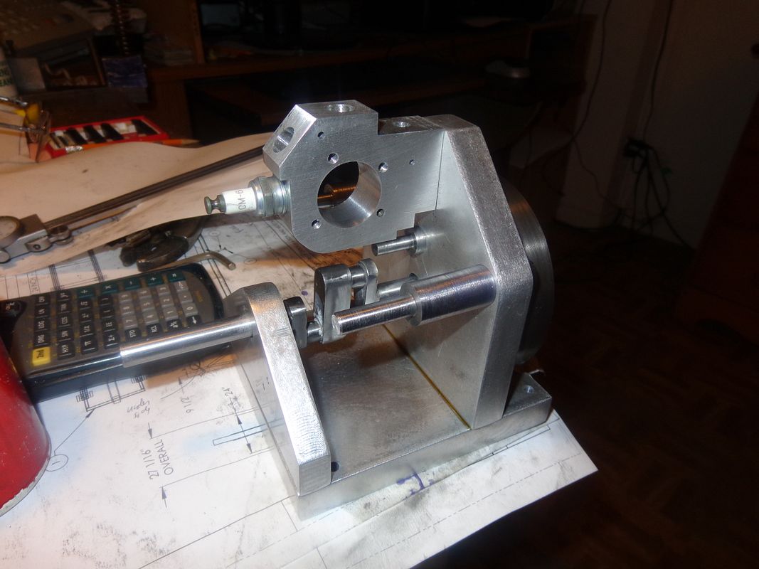
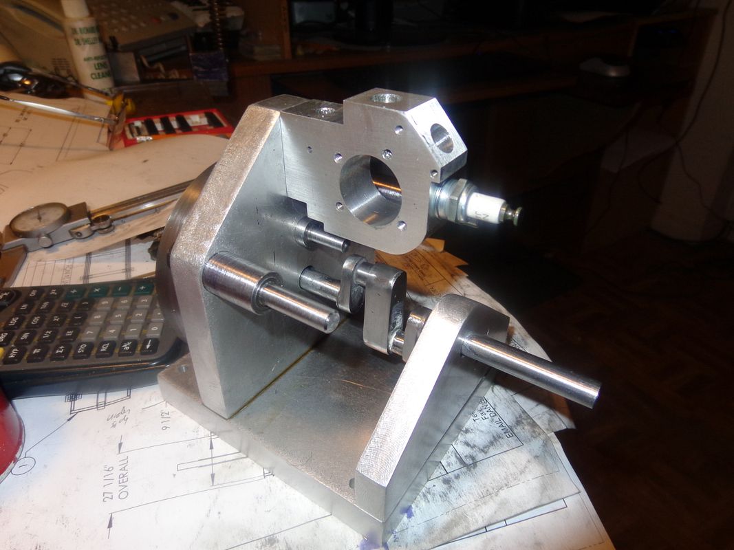
I must say that you have made very great progress with your design and have turned a lot of two-dimensional drawings into the real thing.

It really is a wonderful to be able to watch a concept become a reality, but even better is your sharing with all us forum members. Building an engine is difficult enough without thinking of all the endless details, lighting, set-ups, editing, etc. when the build is to be photographed. However, tutorials like yours are a God-send. I have been reading and posting on this forum for less than one year, and I can't tell you how much I have learned from all the experienced builders that post on this forum.

My hat is off to builders like you who give and share your designs without reservation.


Frank
 
I have decided to devote my weekend to making "easy things". One or two of the drawings I am about to post may have been posted in an earlier version, but they have changed. I am not going back to change previous posts. All drawings will be updated and corrected in the download link at the end of the job.


Latest posts

Back
Top