A different opposed piston engine---

Home Model Engine Machinist Forum

Help Support Home Model Engine Machinist Forum:

This site may earn a commission from merchant affiliate links, including eBay, Amazon, and others.
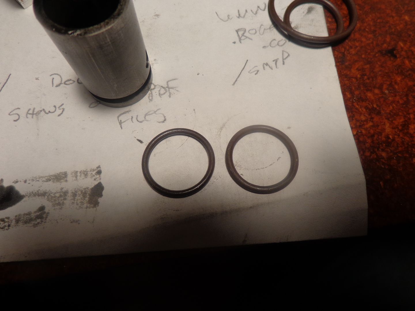
This morning I decided to pull the pistons out of the engine and check the condition of the rings. You may remember that on an earlier post I said I could hear air escaping from the open end of the cylinders when turning the engine by hand on the compression stroke. I surmised that perhaps the inside of my cast iron cylinders might not have been a "mirror finish" and consequently worn some material off the outer diameter of the Viton O-rings during the "break in" phase of running the engine. I pulled the old rings out, and although I couldn't see any specific damaged areas, the whole ring looked slightly smaller than one of the new "spares". It is not much difference. The ring on the right side of the picture is brand new, the ring on the left is one of the worn ones I removed form the engine. HOWEVER--When I reassembled the engine, it is much stiffer to turn over by hand, and there doesn't appear to be any air escaping past the open end of the cylinder on the compression stroke. Since I didn't remove the crankshaft nor bearing supports, this new "stiffness" can only be attributed to the fit of the rings into the cylinder.
 
Gus, the effectiveness of a flywheel is very much tied in to the diameter. According to what I have read 90% of the flywheels effectiveness is concentrated in the outer rim of the flywheel. The larger that rim is in diameter, the more effective the flywheel will be. All single cylinder four stroke engines have an inherent "flaw" in their design. Namely, once the cylinder has fired and the piston has reached the bottom of the stroke, there is absolutely no outside forces to bring the piston back up to top on the exhaust stroke, down again on the intake stroke and up again on the compression stroke. For that a flywheel is necessary. If the flywheel is too light or too small in diameter to carry out this work, then the engine will stall before it can go through all of the necessary moves to let it fire again.--And this ties in directly to how low a speed the engine can run at. A small diameter but very thick flywheel like I originally had on this engine is nowhere near as effective as a flywheel of the same weight, but thinner with a larger diameter.--Brian

Hi Brian,
You are right.
I lost all my notes on Ingersoll-Rand flywheel designs and counterbalancing .
My China Boss called. While cutting cost ,they reduce compressor f/wheel size and weight and got into electric motor overloads with compressor running at same rpm. Gave them this simple formula -------w x r. That is to calculate and compare both old and new f/w wrs. New wheel redone and motor full load current back to normal.
Plan to read up on locomotive balancing.Just to see where we are in flywheel
selection for our i.c. engines.
 
The larger diameter flywheel made quite a big difference, just as I thought it would. Perhaps it isn't running as slowly as the Webster can, but there are a lot more moving parts to this engine. My total flywheel weight is about the same as it was before when it was 3 7/8" diameter x 1 5/8" thick, only now it is 3/4" thick x 6" diameter. I will not be posting any more about this engine until I find something for it to actually power.---Brian
 
And thanks for the update .. it has been a real education following your progress.

Keep-um coming! :):)


Pat H.
 
Since I am having a very boring morning, and its still to cold to play outside, I have arranged a spectacle for your amusement. I have added the engine, the clutch, and the much beloved marble machine into a mechanical daisy chain, just to see what would happen. The marble machine is not in top form, as I seen it drop a couple of balls and because I have never completed the ball return track, but it runs quite well enough for a fun demonstration.--Enjoy!!!
 
That extra weight on the flywheel made a huge difference. I could sit and listen to that engine idle all day long, such a sweet sound!

Chuck
 
Well Done Brian!! I agree with chuck ... asweet sounding engine for sure.

Cheers,

Tom
 
Your engine ran smoothly with the bigger/heavier flywheel.
Bought " Mechanical Engineering Design'' by Shigley from Amazon to read up
on flywheel designs.Hopefully all my future flywheels will have the best weight and diameter to run engines smoother.
May also emailed ex-IR colleaques on the formula used for air compressor flywheels.
 
Just a final post to end off this thread in case someone finds it in the future, The engine ran well, but the crankshaft was not straight, and consequently the aluminum wheel on the front of the engine danced around in a very unsightly manner. I have removed the crankshaft and replaced the "bad end" and now it runs true.
 
Loved the whole thread and documented engine build. I especially liked the frustrating, "fails". When somebody who is brilliant, fails, and then solves the problems....we all benefit. We learn what not to do.

I will never know what Mr. Rupnow knows. But he, along with some others ( G. Britnell, S. Huck, C. Fellows, etc. etc.) on this forum have set the high-water mark. Their goal is, and will always be....excellence without compromise.

Good teachers to have in this 'school'. I wish I had these kind of guys around me when I was growing up.


Frank
 
So,

Foot-in-mouth disease. I asked about this under load (in the "wonky crankshaft" thread) and you did it and I missed it.

I still think you get double thanks for keeping after this project to make it better and better with each tweak.
--
ShopShoe
 
Very Well Done Brian. The whole engine seems to be smoother now so the bearings must have made a difference as well.

After all the mods and trials and tribulations you went through, you deserve a break.

Again, I really enjoyed this thread and appreciate all your efforts.

Cheers,

Tom
 
To revive an old thread and cry "mea culpa" to all who suggested an outboard support for the cantilevered stub shafts. I haven't really ran the engine much at all since I built it and straightened the crankshaft. Last week when I was searching for an engine to run the model buzz saw I built, I noticed a strange phenomenon. Although the cantilevered stub-shafts didn't visually deflect when the engine was running, they must have at some level, because the bolts through the main backplate which anchored the stub shafts in their pockets in the main engine backplate would loosen off after about 10 minutes running, no matter how much they were tightened.Then the cantilevered stub shafts would indeed move all over the place. This presented a major pain in the butt, because I had to remove the large diameter flywheel on the back side of the engine to get at the bolt heads and re-tighten them. After removing the flywheel twice to tighten the bolts, I decided that yes, everyone who suggested an outboard support for the cantilevered shafts was right and I was wrong. So--I redesigned the removable front plate and added a couple of "extensions" with pockets to hold the extended end of the no longer cantilevered stub shafts. I made new, longer stub shafts and drilled the extended ends for #8-32 bolts. This actually entailed a couple of days work and almost total disassembly of the engine, however the engine is now solid as a rock when it runs, and I filled up a couple of horribly cold winter days with something to do.
 
I see that Barnbikes has sent me an article about opposed piston engines. I designed this one in 2008 and posted about it here. It is a sweet running engine, and has a lot of very interesting parts.---Brian
 
Back
Top