You are using an out of date browser. It may not display this or other websites correctly.
You should upgrade or use an alternative browser.
You should upgrade or use an alternative browser.
A different opposed piston engine---
- Thread starter Brian Rupnow
- Start date

Help Support Home Model Engine Machinist Forum:
This site may earn a commission from merchant affiliate
links, including eBay, Amazon, and others.
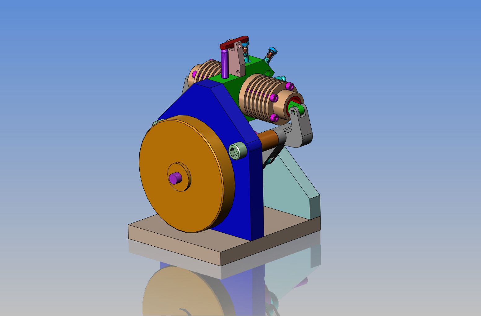
I don't see a great deal of sense in spending a lot of time machining a fancy flywheel for an engine like this. All of the "monkey motion" and neat stuff to see working will be on the "front" side of the engine. What I have shown here is simply a 4" diameter disc of mild steel or possibly cast iron, with a boss on each side. The boss on the side towards the main vertical plate is 7/16" long x 1" diameter, long enough to stand the main body of the flywheel out clear of the 3/8" bolt heads which are holding the stand-offs in place. The boss on the exposed side is 1" diameter x 1/8" long, and serves no purpose other than a cosmetic one.

I suggest this engine configuration is most advantageous as a 2-stroke, such as the Deltic & T3 already mentioned, where ports at opposite ends provide excellent scavenging, especially with a blower.
The arrangement is is also useful for research, as an eccentric mounting of the rocker shaft allows simple adjustment of the compression ratio.
As a 4-stroke I don't see anything much to recommend it, other than it is slightly oddball. But hey, you're doing it, not me.
BTW if you are not familliar with them, Deltics in particular have a wonderfully distinctive sound:
[ame]http://www.youtube.com/watch?v=ggm1YVith44[/ame]
the Commer is distinctive too:
[ame]http://www.youtube.com/watch?v=e0sLp7wvq60[/ame]
- Joined
- May 27, 2010
- Messages
- 2,999
- Reaction score
- 1,171
Looks simpler and less parts to build than the Nemett-Lynx IC Engine. I am keen but will have to wait after I finish up the H&M.
Due to the physical shape of this engine, I won't be able to screw the exhaust pipe nor the carburetor into the center block, because they will hit on the cylinders and not be able to turn. Consequently, they will both have to be attached with bolt on flanges and some of gasket. I like to run a bit of two cycle oil with my Coleman fuel to lubricate the cylinder and piston, so the exhaust is always messy--so---I ran the exhaust pipe out towards the back side of the engine. If I need to, I can add an auxiliary bracket from the exhaust pipe to the main vertical backing plate. The "intake manifold" for the carburetor will be an unusual shape, but it serves to move the carburetor away from both the cylinder and the sparkplug.
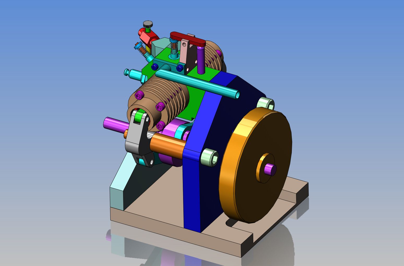
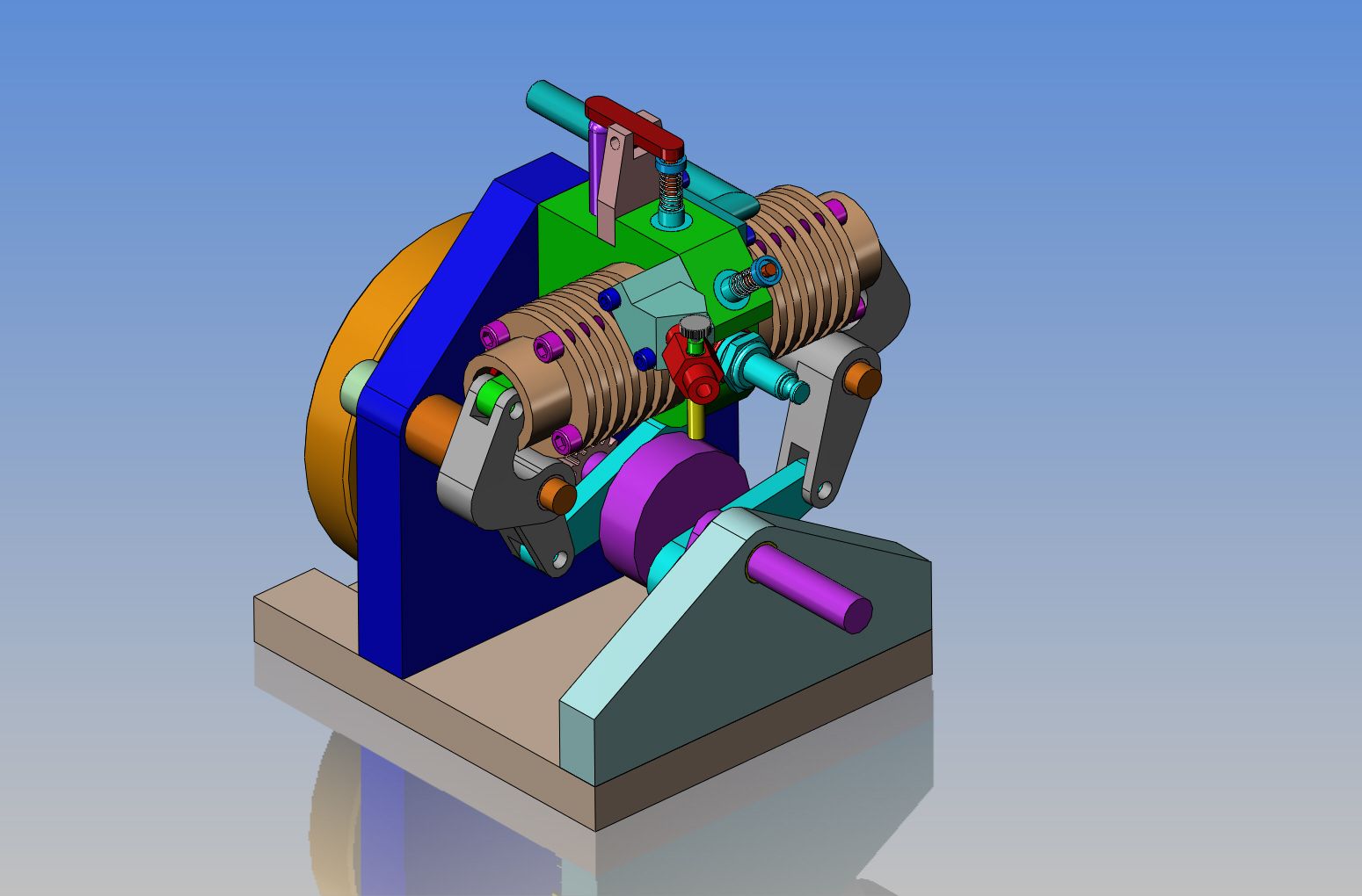


Today I made a little time to add the snap ring grooves to the end of the cam shaft and "stand-off" pivot shafts, and downloaded some snap ring models from McMaster Carr's website. This pretty well completes the design of this engine, except for the ignition. I really wish I could just embed a magnet in the flywheel to trigger the hall effect switch for my ignition spark, but my understanding is that the magnet must be embedded in some material that is non magnetic, to work properly. I don't want to add anything more to the front side of the engine. I could use brass for the flywheel, but that would cost about a zillion dollars. Aluminum is too light to make a flywheel from. What do you think of this idea---Make the 5/8" thick flywheel from steel or cast iron, but drill a 1/2" hole 1.5" deep and Loctite in a 1/2" diameter x 1.5" long plug of round brass into the hole (close to the same relative density/weight) and Loctite the magnet in a pocket drilled in the outer end of the brass plug. I don't know if that would work or not.

Hi Brian
Have have read somewhere that your idea of embedding the magnet into a none magnetic plug is totally acceptable, sorry cannot remember where I read it but I suspect it was on Jan Ridders website, I am building Jan's opposed piston two stroke and will by embedding the magnet in a plug into the steel flywheel. I would love to build this engine!!!
Dave
Hi Dave---I have looked at Jan Ridders opposed piston engine, and its very impressive. Of course, being a design maniac, I wanted to design my own version. The "Rupnow Engine" was the first engine that I have fully designed, and it works quite well, but I learned a few things, and will apply them to this new engine. I do hope I can get confirmation that my "brass insert with magnet" will work, because it would keep the design very clean and simple.---Brian
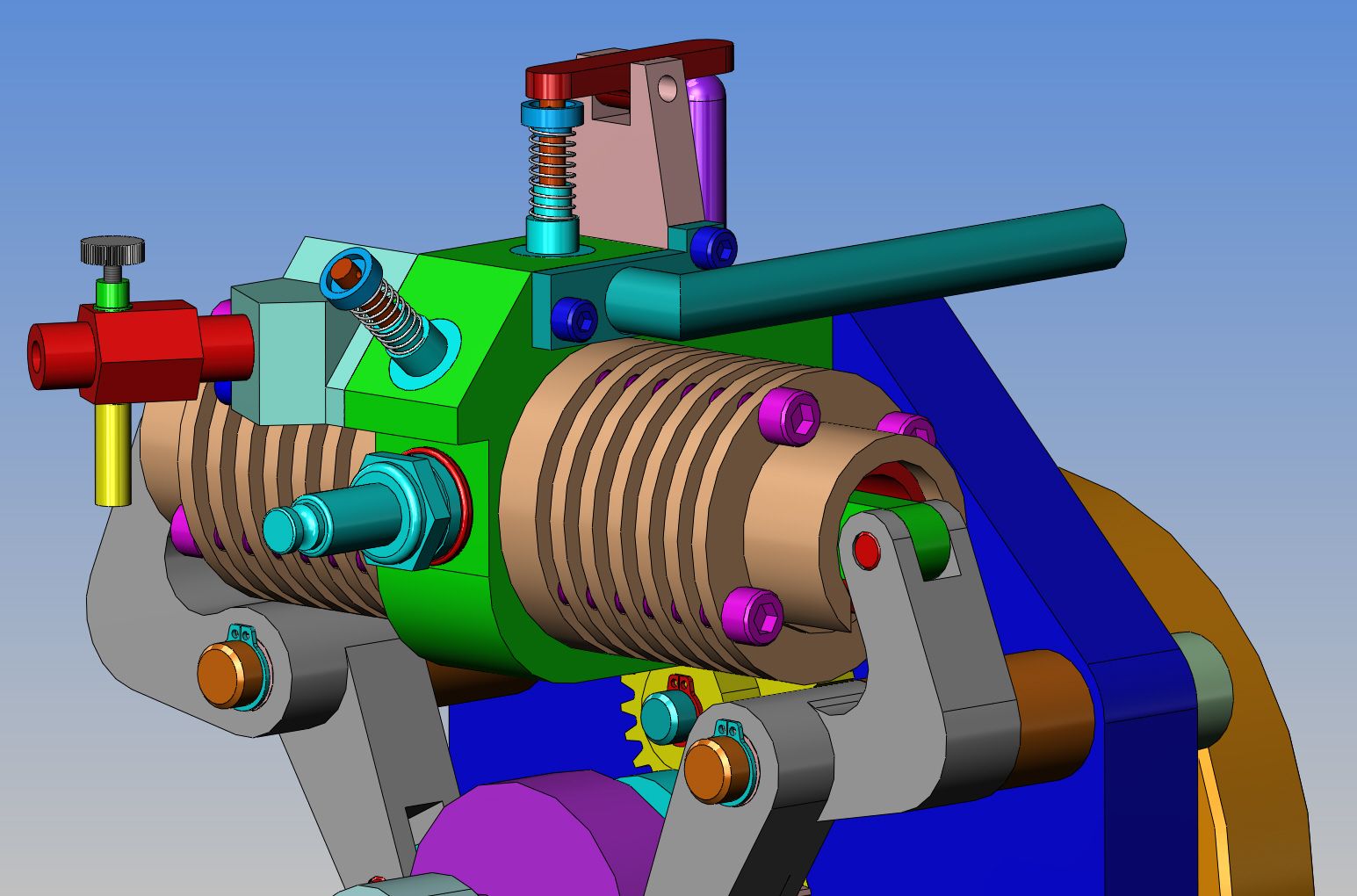
Okay--Here's what I did for my ignition, and why I did it. Having the magnet embedded in the flywheel sounds like a great idea. Trouble is, the flywheel will be keyed to the crankshaft, so there is no real handy way to adjust the ignition timing. To keep things simple, the green disc on the front of the engine is aluminum with the magnet Loctited into a pocket in the face of the disc. The disc is located rotationally on the crankshaft with a single flat ended socket head set screw. The hall effect sensor , mounted in the D-tube (the red thing) is supported by one bracket mounted to the face of the front bearing support. I have chosen to not make the bracket adjustable so consequently I can't change the engine timing while the engine is running. If I want to adjust the timing, I stop the engine, loosen the set screw, and turn the disc one way or the other, then retighten the set screw. This has no effect on the valve timing, because the relationship between the crankshaft gear and the timing gear is not affected by doing this. On the previous engine I built last summer, I had the bracket adjustable, but I found that once you get the engine running the first time, you never adjust the timing anyways.


Last edited:
Swifty
Well-Known Member
A really great design Brian, can't wait until you start building this one.
Paul.
Paul.
vederstein
Must do dumb things....
- Joined
- Feb 26, 2011
- Messages
- 917
- Reaction score
- 744
Here's a Youtube link on a similar design of engine:
[ame]http://youtu.be/pGaISFg_ZIw[/ame]
[ame]http://youtu.be/pGaISFg_ZIw[/ame]
vederstein---That engine is the one which was the basis for my design. You will see that the one in the video is a diesel with a roots style blower. Mine will be a 4 cycle with spark ignition.
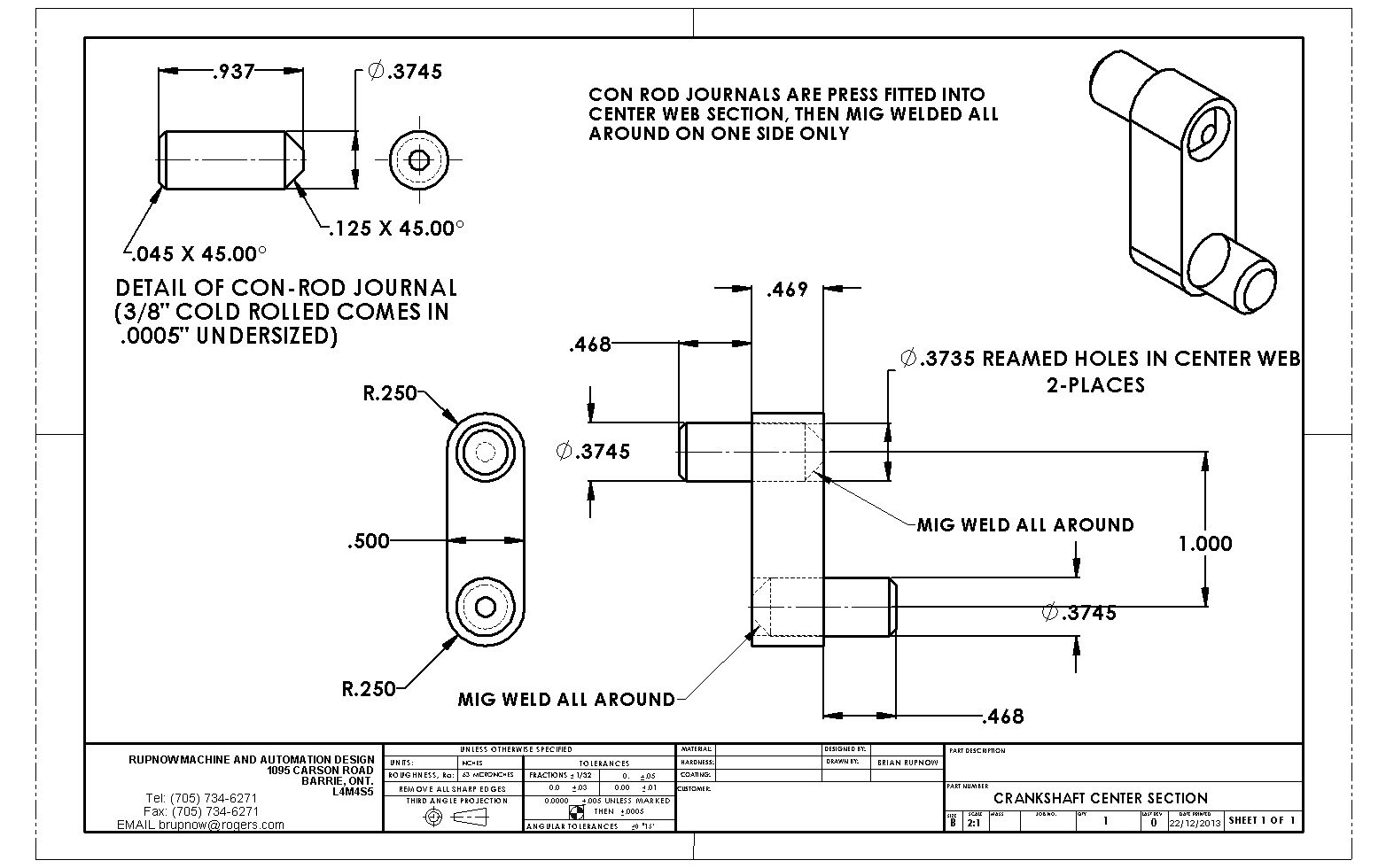
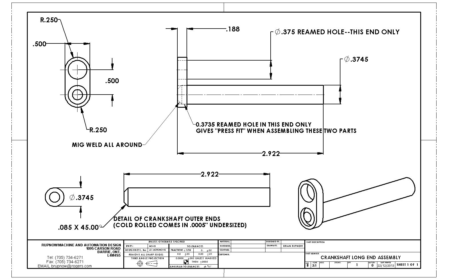
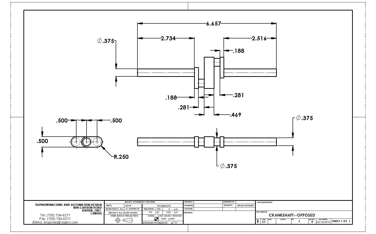
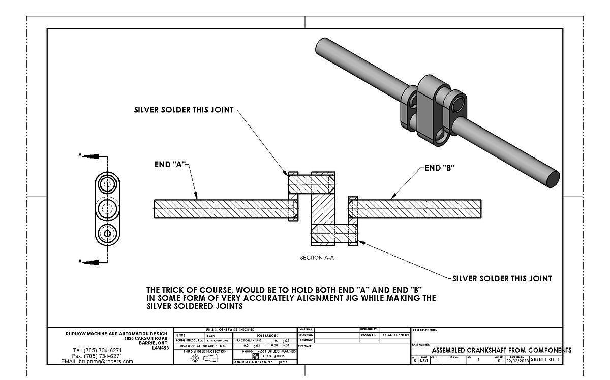
As always, I find that the hardest part for me to build is the crankshaft.--So---That is where I tend to go first. If I can build the hardest part, then everything else is (or should be) downhill from there. The crankshaft is 3/8" diameter. The outer "webs" are 3/16" thick, and the center web is .469". The space between the webs is 9/32", and the actual "throw" of the crankshaft, from the centerline out to either of the con rod journals is 0.5". The con-rod journals are also 3/8" diameter. The webs are all 1/2" wide. All I have to do now is decide whether to machine this all from one piece of hot-rolled steel, or to do a built up and silver soldered crankshaft. Both have their own unique difficulties, and each represent a lot of work if I screw it up----


This is the crankshaft, and if I was feeling really bold, I would machine it completely from one piece of steel. I lay in bed last night, and decided to take the cowards way out and build it up from pieces, in a rather unorthodox fashion. I have the material on hand, and if it works, it will be one of the easier crankshafts I have made.---If it works!!!

Then, in a perfect world, if I could make a good fixture to align the two ends of the crankshaft, I should be able to silver solder the last two joints to end up with a perfectly aligned crankshaft. A point to note, is that the last two joints to be assembled would not be a press fit.--I do want the silver solder to "wick" into the joint. When mig weld solidifies, it has a tendency to pull the welded components out of alignment. Silver solder doesn't do that, because the entire joint has to be heated to a uniform temperature for the silver solder to melt and flow around, so there are no thermal stresses trying to pull the metal to one side or the other. I have never tried to build a crankshaft like this before, but it certainly has an appeal to me. I will build one and take a few pictures to let you know how it goes.---Almost makes me wish I had an old lathe so I could grip one end in the 3 jaw chuck and the other end in the tailstock chuck before doing the final silver soldering!!!

Niels Abildgaard
Well-Known Member
- Joined
- Jun 13, 2010
- Messages
- 546
- Reaction score
- 98
Hello Brian
There is a lot of forces on the rocking arms and I suggest that You unite the cantilevered rocking shaft free ends with a tie rod of some kind.
Kind regards
There is a lot of forces on the rocking arms and I suggest that You unite the cantilevered rocking shaft free ends with a tie rod of some kind.
Kind regards
Last edited:
Similar threads
- Replies
- 115
- Views
- 8K
- Replies
- 25
- Views
- 3K


